
LidarBot
SKU:K017-C
Description
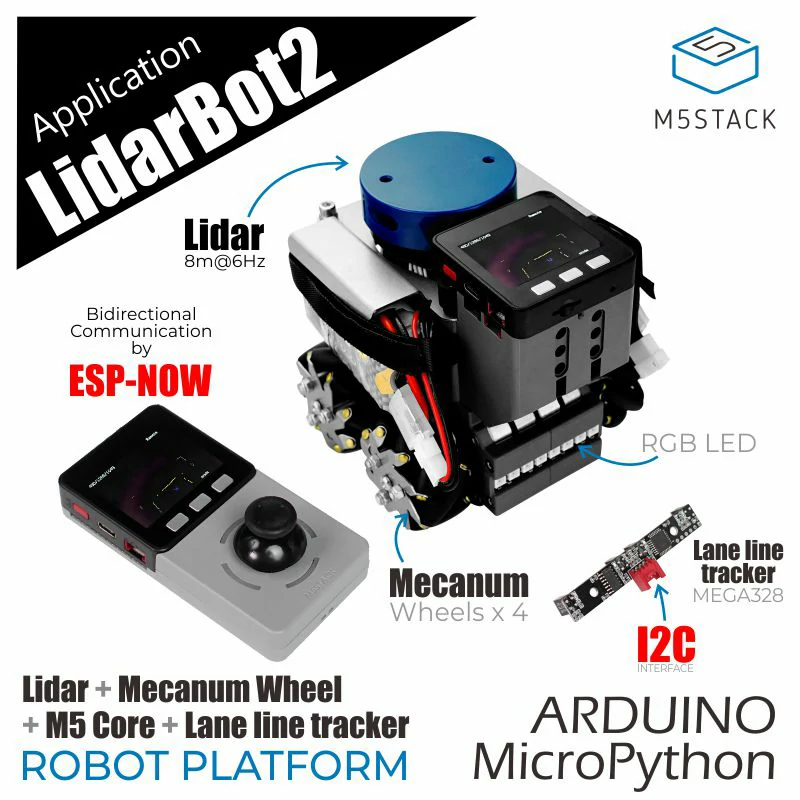
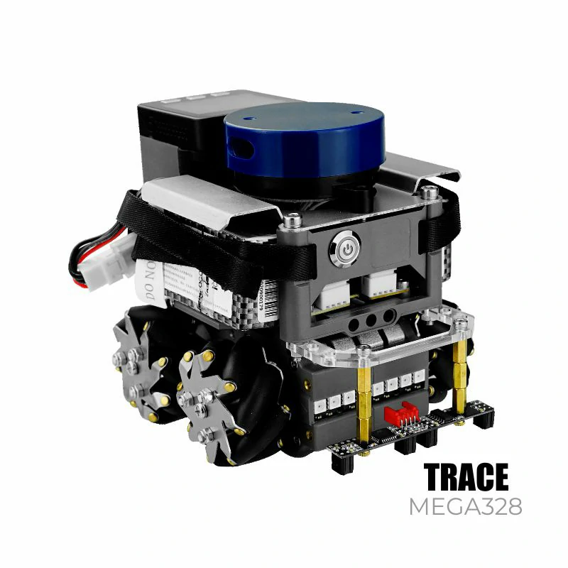
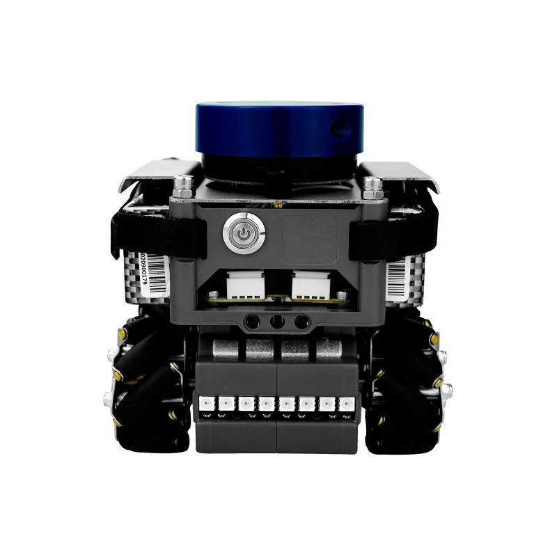
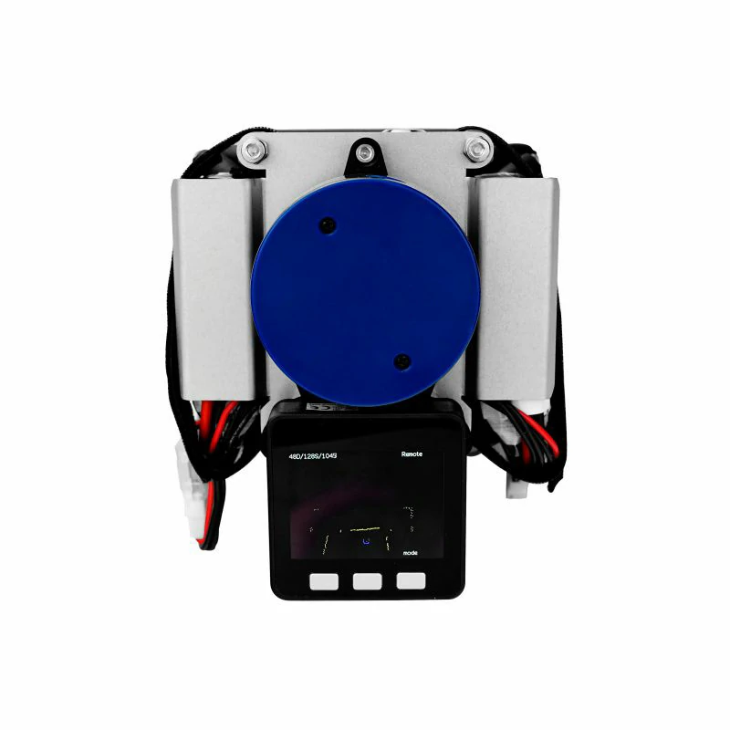
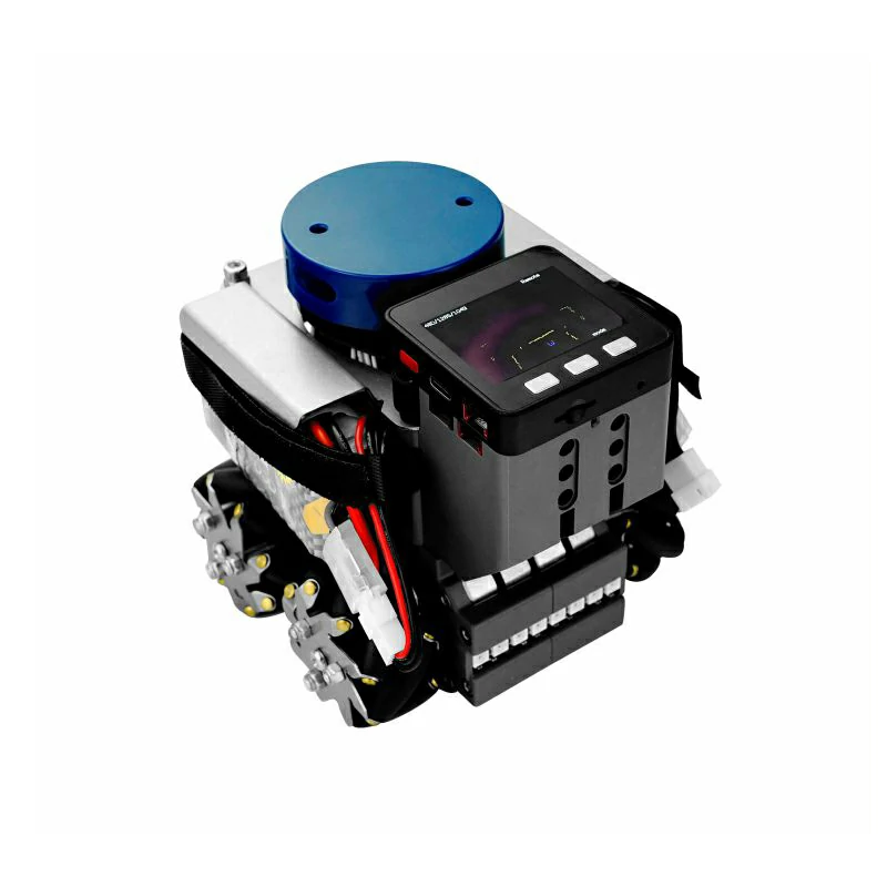
LidarBot is a LiDAR car equipped with a 360° LiDAR sensor, M5Core main control, 4 Mecanum wheels, a wheel control baseboard (integrated with MEGA328), an RGB light strip, a joystick controller, and more. Additionally, it comes with a TRACE tracking module kit for black-and-white line recognition. Based on Mecanum wheel technology, the omnidirectional car can achieve movements such as forward, lateral, diagonal, rotation, and combinations thereof. A high-capacity lithium battery provides long-lasting power for the LiDAR car.
The controller and LidarBot communicate in real-time via ESP-NOW. During operation, you can view the map data scanned by the LiDAR sensor on the controller screen. We provide open-source code on GitHub, based on the official source code, allowing you to transmit LiDAR scan data and other collected data via Wi-Fi or other methods to other nodes. LidarBot can be used in STEM education for programming learning, competitions, and other activities. Moreover, its powerful functionality makes it suitable for developers in the AGV development field for project development.
Features
- EAI YDLIDAR X2 LiDAR range and speed: 8m @ 7Hz
- ESP-NOW remote control
- Line tracking capability
- Development platforms:
- Arduino
- UiFlow
- LEGO compatible
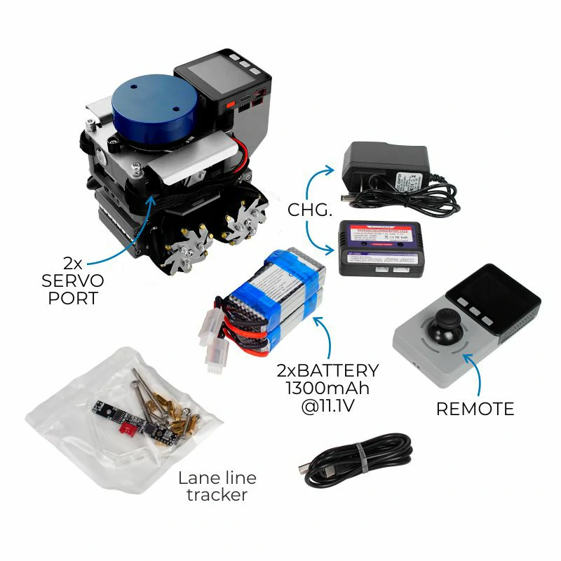
Includes
- 1 x LidarBot
- 1 x Remote control handle
- 1 x Tracking module kit
- 2 x Batteries (1300mAh @ 11.1V)
- 1 x Battery charger
- 1 x Type-C USB cable
Applications
- Indoor navigation
- Autonomous maze solving
- Path planning
- Autonomous driving
Specifications
| Specification | Parameters |
|---|---|
| MCU | STM32F030F4P6 |
| Net weight | 1980.0g |
| Gross weight | 2140.0g |
| Product size | 142 x 117 x 120mm |
| Package size | 208 x 208 x 167mm |
Learn
Connection and Pairing
In an unconnected state or if one side is not connected to the other, display or control issues may arise. In such cases, a reconnection is necessary.
- For the LiDAR car, hold down the C button and press the M5Core power button. Wait for the screen to restart, then release the C button to enter broadcast mode. All slave devices will receive the signal from the host.
- With the LiDAR car in broadcast mode, hold down the C button on the controller and press the controller's power button. Wait for the controller to restart, then release the C button. The screen will display the current broadcasting host. Use the A/C buttons to navigate up and down, then press the B button to select the desired host's MAC address. The host's MAC address can be viewed by checking nearby Wi-Fi networks on a phone or computer, starting with "lidar" followed by the host's MAC address.
- After confirming the host, the host (LiDAR car) screen will receive the confirmation signal from the slave (controller). Use the ABC buttons to select and confirm the slave (controller) address. Once the B button is pressed to confirm, the LiDAR car and controller will complete the communication configuration, allowing them to exchange messages and display radar maps and control the car.
Control and Display
With the LiDAR car and controller paired, they can exchange messages via ESP-NOW. The LiDAR car's radar information can be displayed on the controller, and the controller can control the car's movement via ESP-NOW.
- Normal control mode: Move the joystick to control the car's forward, backward, and turning movements.
- Omnidirectional control mode: Hold down the A button (the leftmost button on the controller screen) and move the joystick to achieve lateral movement, but the forward and backward directions will be reversed.
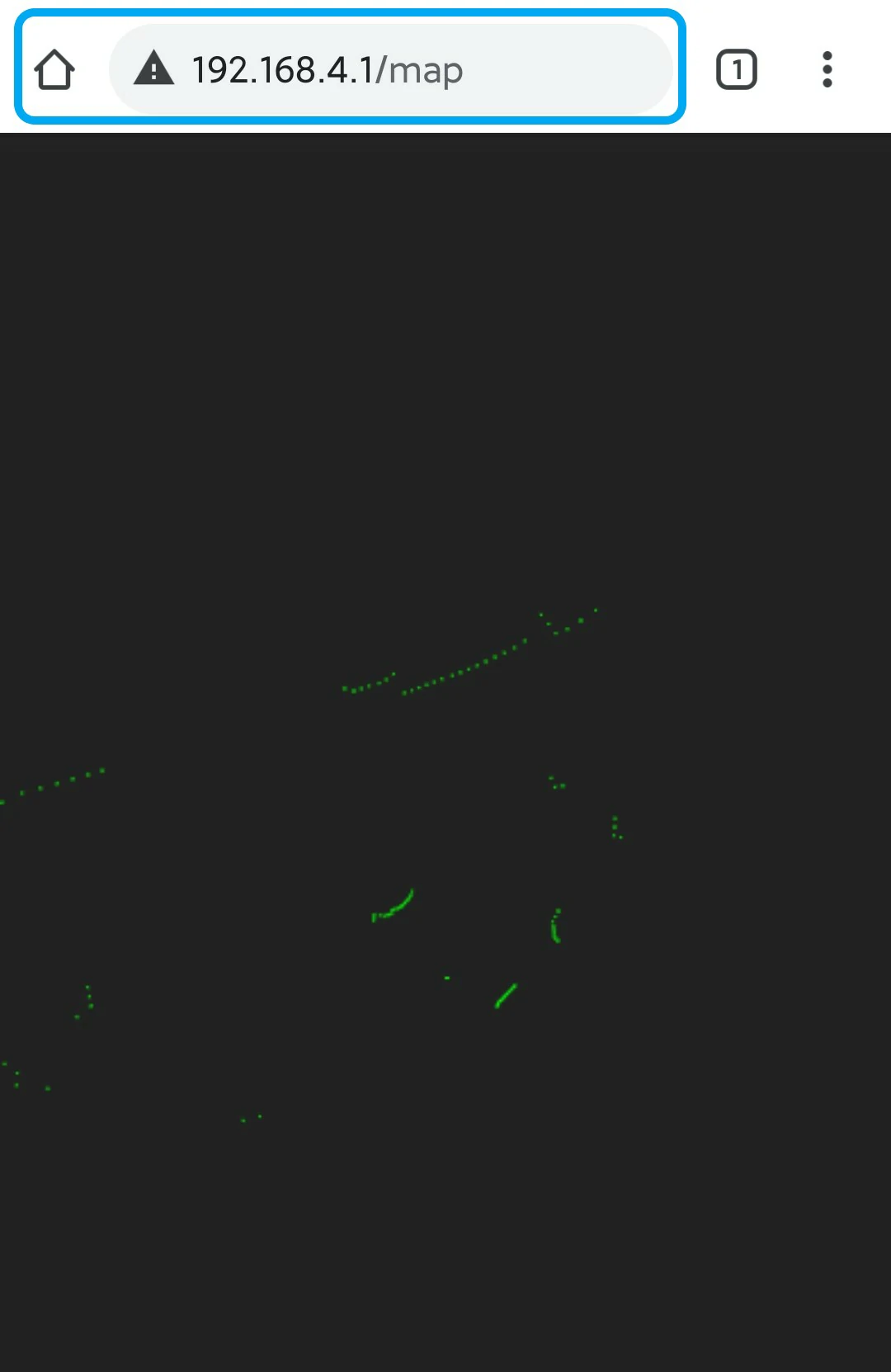
Web Display of Radar Image
After the LiDAR car starts up, without needing to pair with the controller, you can connect to the LiDAR car's Wi-Fi hotspot (SSID: X2Lidar:xx:xx:xx, PWD: 12345678). Then, access 192.168.4.1/map via a phone or computer browser to view the radar image.
Datasheets
Softwares
Arduino
Protocol
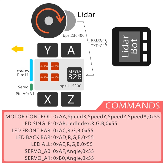
Protocol Between Main Control and Baseboard
Protocol format: Frame header (command type) + Data frame + Frame tail
| Protocol Object | Protocol Format | Example | Call Function |
|---|---|---|---|
| Wheels | 0xAA,SpeedX(-7 ~ 7),SpeedY,SpeedZ,SpeedA,0x55 | 0xAA, 5, 5, 5, 5, 0x55 (Forward, speed: 5) | ControlWheel(5, 5, 5) |
| One RGB | 0xAB,LedIndex,R(0 ~ 254),G,B,0x55 | 0xAB, 3, 20, 50, 100, 0x55 (Light up LED 3 with specified color) | setLedColor(3, 20, 50, 100) |
| Front RGB Bar | 0xAC,R(0 ~ 254),G,B,0x55 | 0xAC, 20, 50, 100, 0x55 (Light up front LED bar with specified color) | setFrontLedBar(20, 50, 100) |
| Back RGB Bar | 0xAD,R(0 ~ 254),G,B,0x55 | 0xAD, 20, 50, 100, 0x55 (Light up back LED bar with specified color) | setBackLedBar(20, 50, 100) |
| All RGB | 0xAE,R(0 ~ 254),G,B,0x55 | 0xAE, 20, 50, 100, 0x55 (Light up all LED bars with specified color) | setLedAll(20, 50, 100) |
| ServoMotor0 | 0xAF,Angle(0 ~ 180),0x55 | 0xAF, 100, 0x55 (Servo 0 rotates to 100°) | setServo0Angle(100) |
| ServoMotor1 | 0xB0,Angle(0 ~ 180),0x55 | 0xB0, 100, 0x55 (Servo 1 rotates to 100°) | setServo1Angle(100) |
Parameters
- Communication parameters
- M5Core (car main control) <-> LiDAR U1RXD(GPIO16) <-> LiDAR Serial port configuration: "115200bps, 8, n, 1" (8-bit data, no parity, 1 stop bit)
- M5Core (car main control) <-> Control baseboard U2TXD(GPIO17) <-> Control baseboard Serial port configuration: "115200bps, 8, n, 1" (8-bit data, no parity, 1 stop bit)
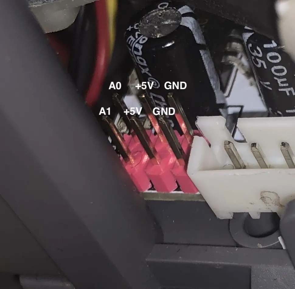
- Interfaces
- Servo 0 <-> A0(MEGA328)
- Servo 1 <-> A1(MEGA328)
- RGB LED <-> 11(MEGA328)
Easyloader
| Easyloader | Download Link | Notes |
|---|---|---|
| LidarBot Master Firmware Easyloader | download | / |
| LidarBot Remote Firmware Easyloader | download | / |
Video
- LidarBot Case Study
Version Change
| Release Date | Product Changes | Note |
|---|---|---|
| 2019.7 | Adopted EAI YDLIDAR X2 LiDAR model; added sheet metal structural part SKU: K017 -> K017-C | LiDAR ranging speed 8m @ 6Hz -> 8m @ 7Hz |
| 2018.12 | First release | / |