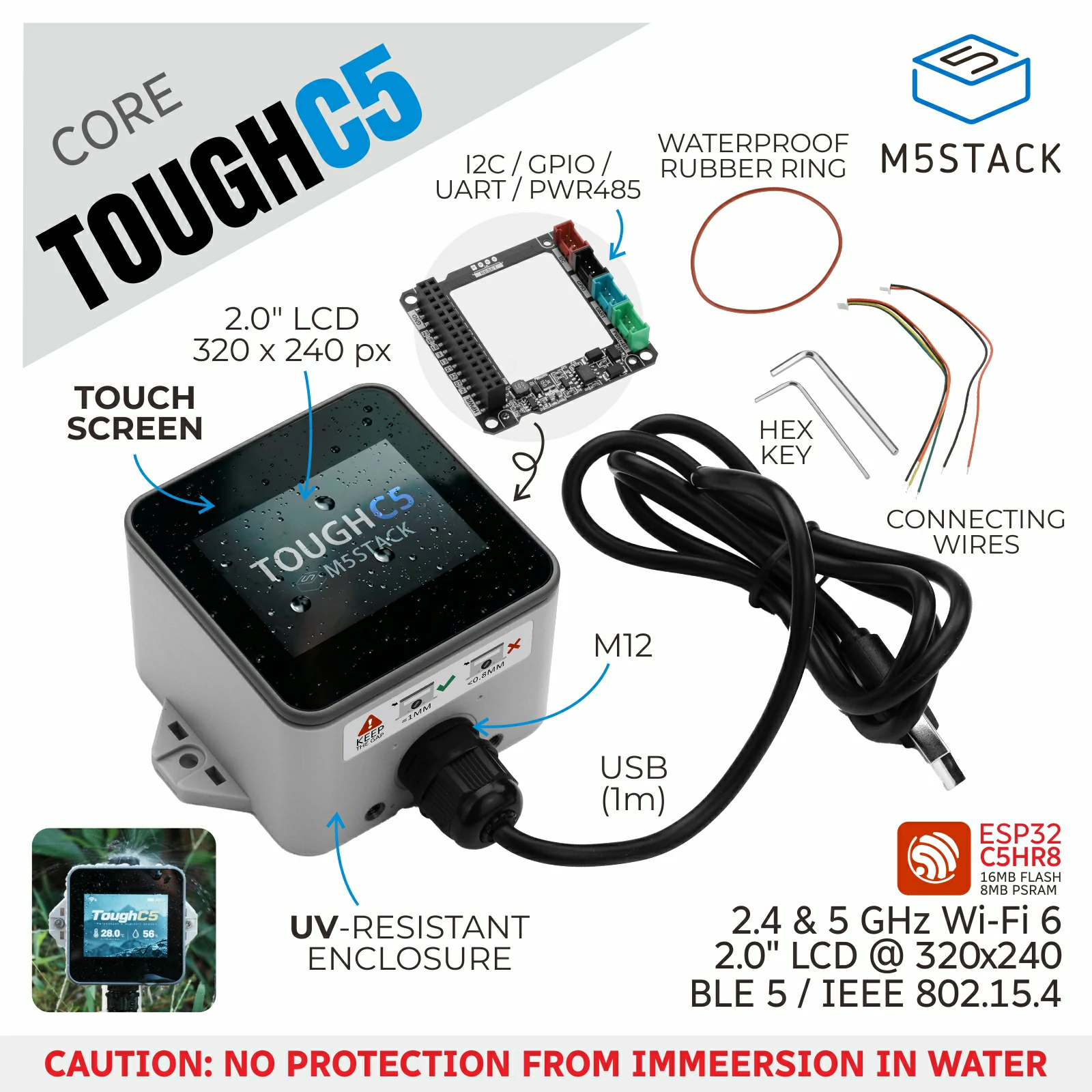
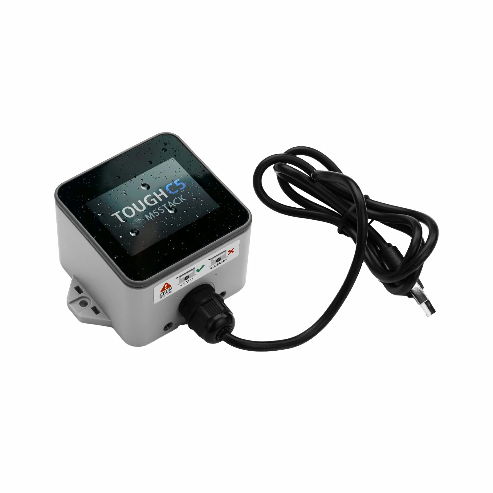
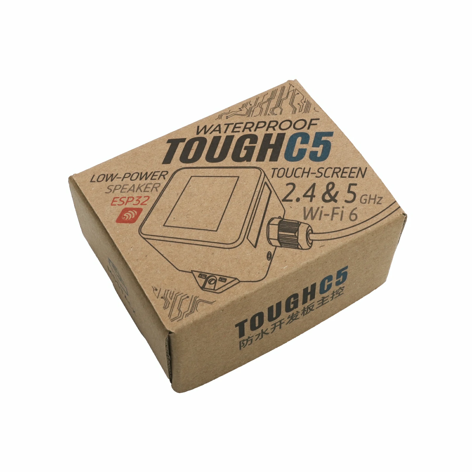
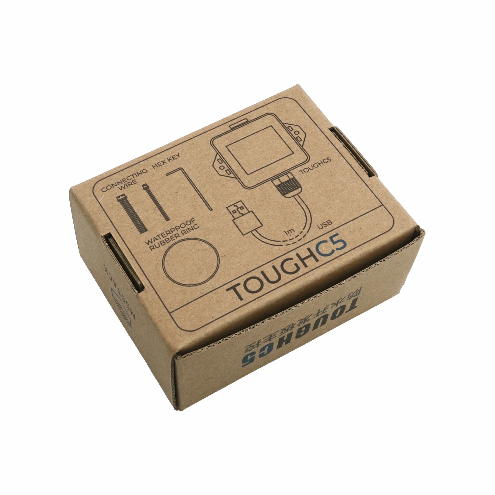
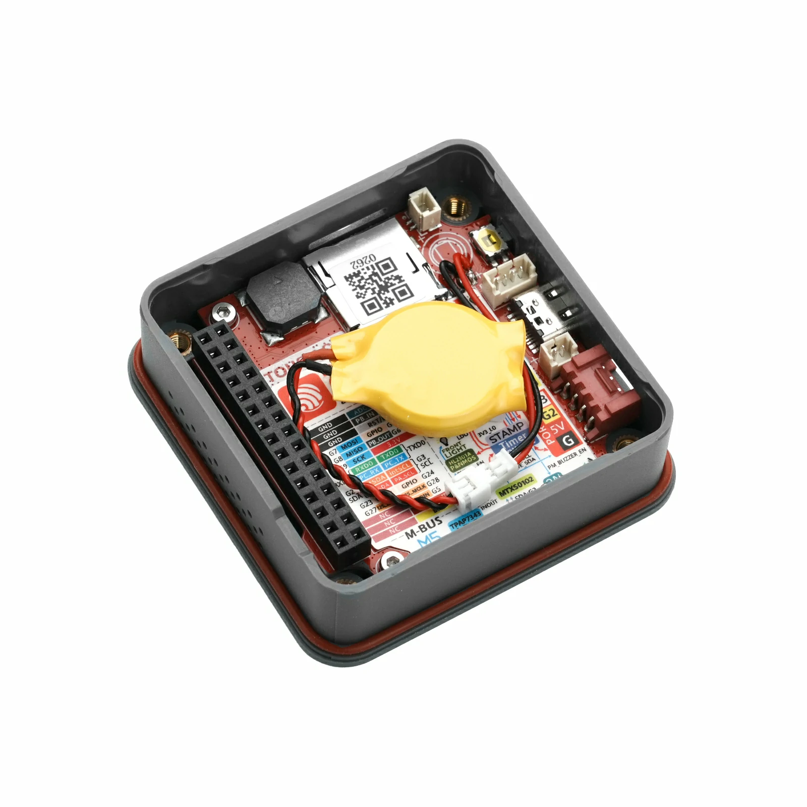
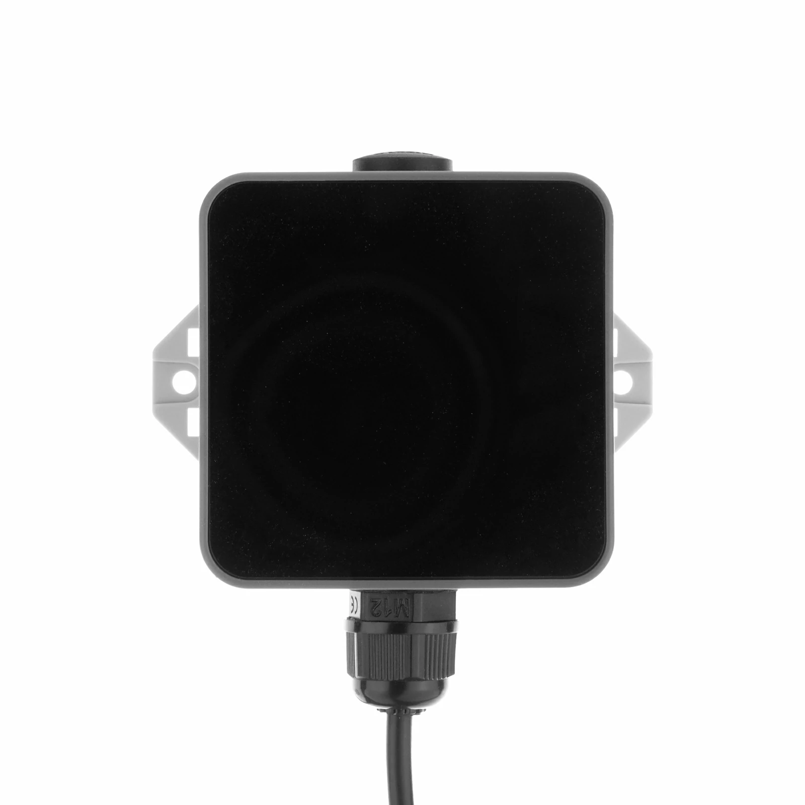
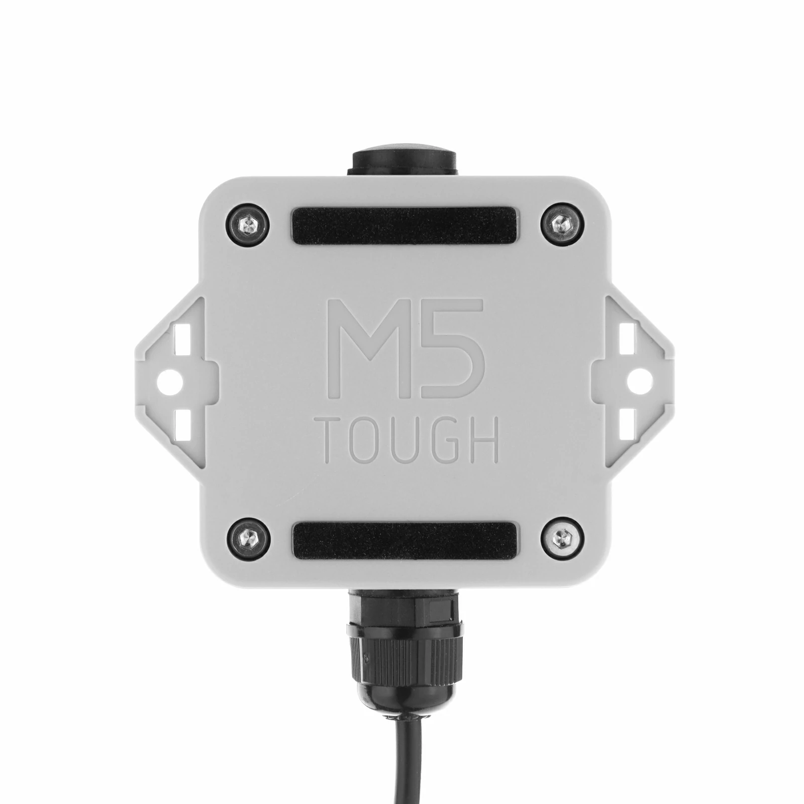
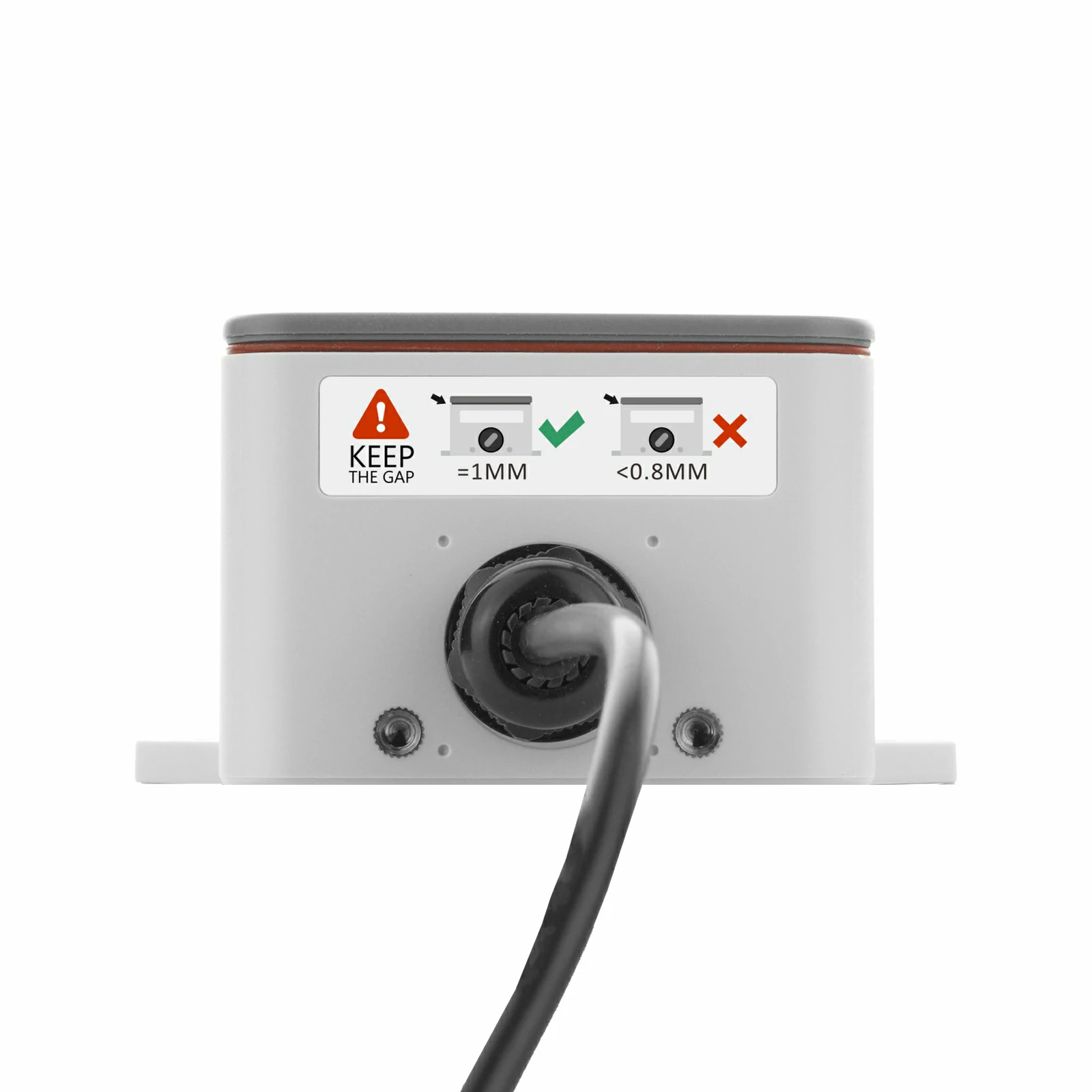
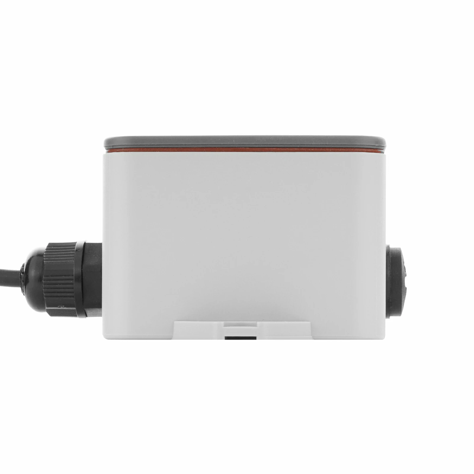
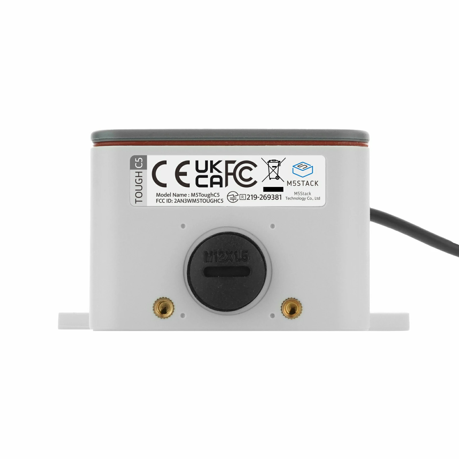
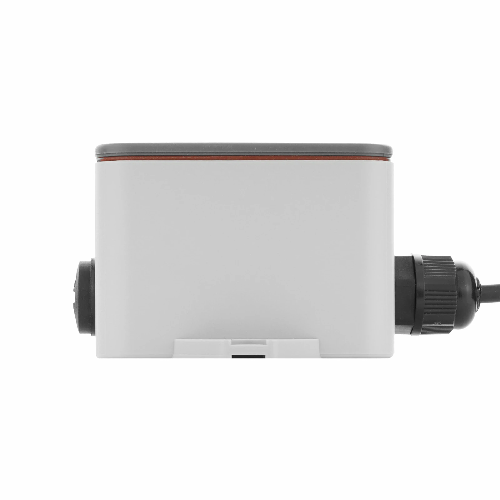
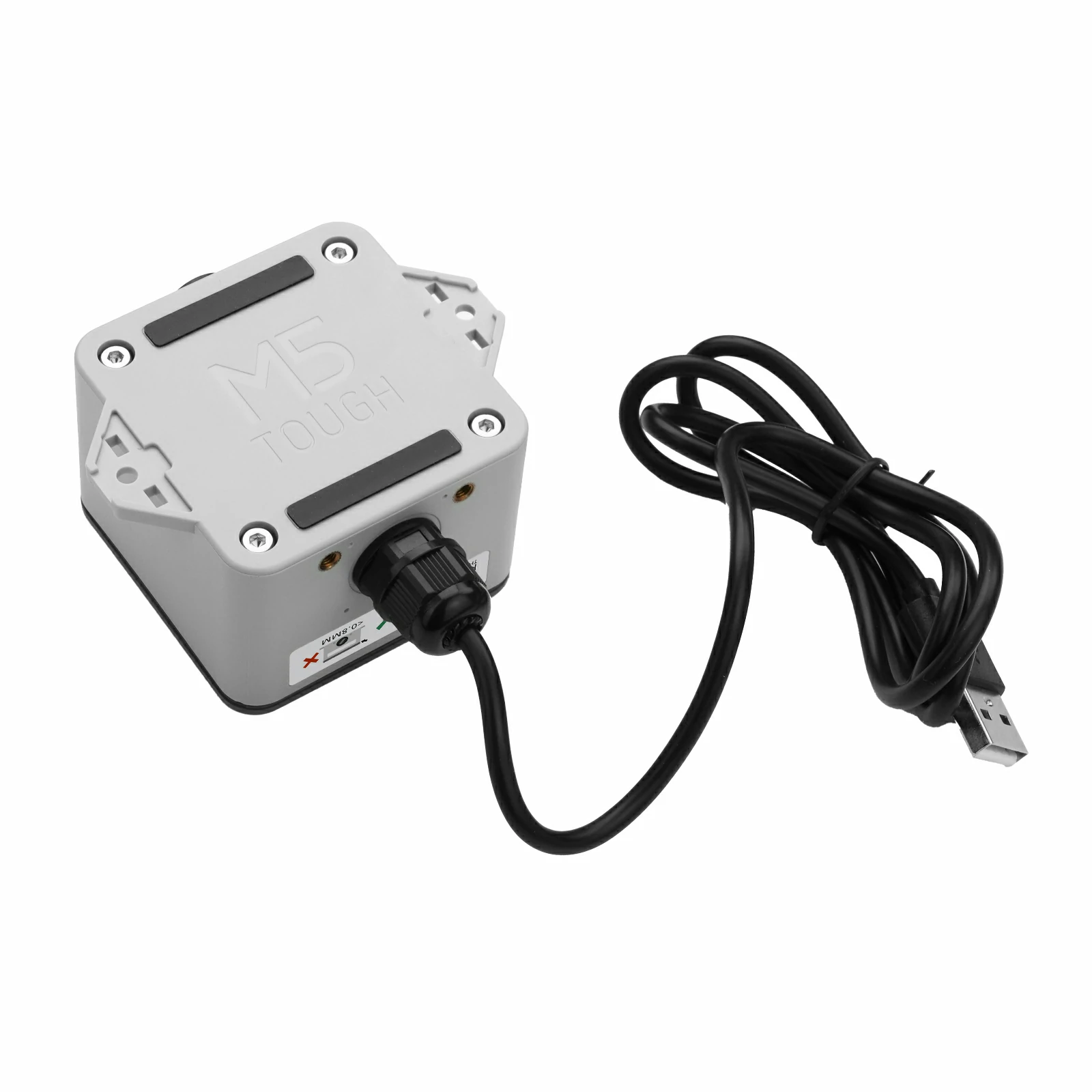
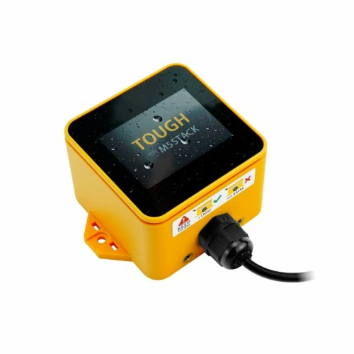
ToughC5 is an outdoor waterproof IoT controller. Built around the ESP32-C5HR8 core module, it features a RISC-V 32-bit single-core processor running at 240MHz, with 16MB Flash and 8MB PSRAM. It supports 2.4 & 5 GHz dual-band Wi-Fi 6, BLE 5, and IEEE 802.15.4 (Zigbee, Thread) multi-protocol connectivity, meeting access requirements across a variety of network scenarios.
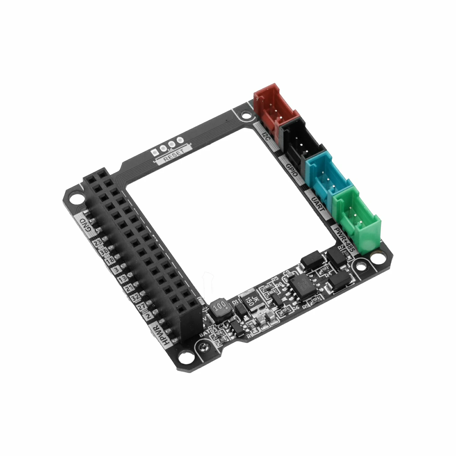
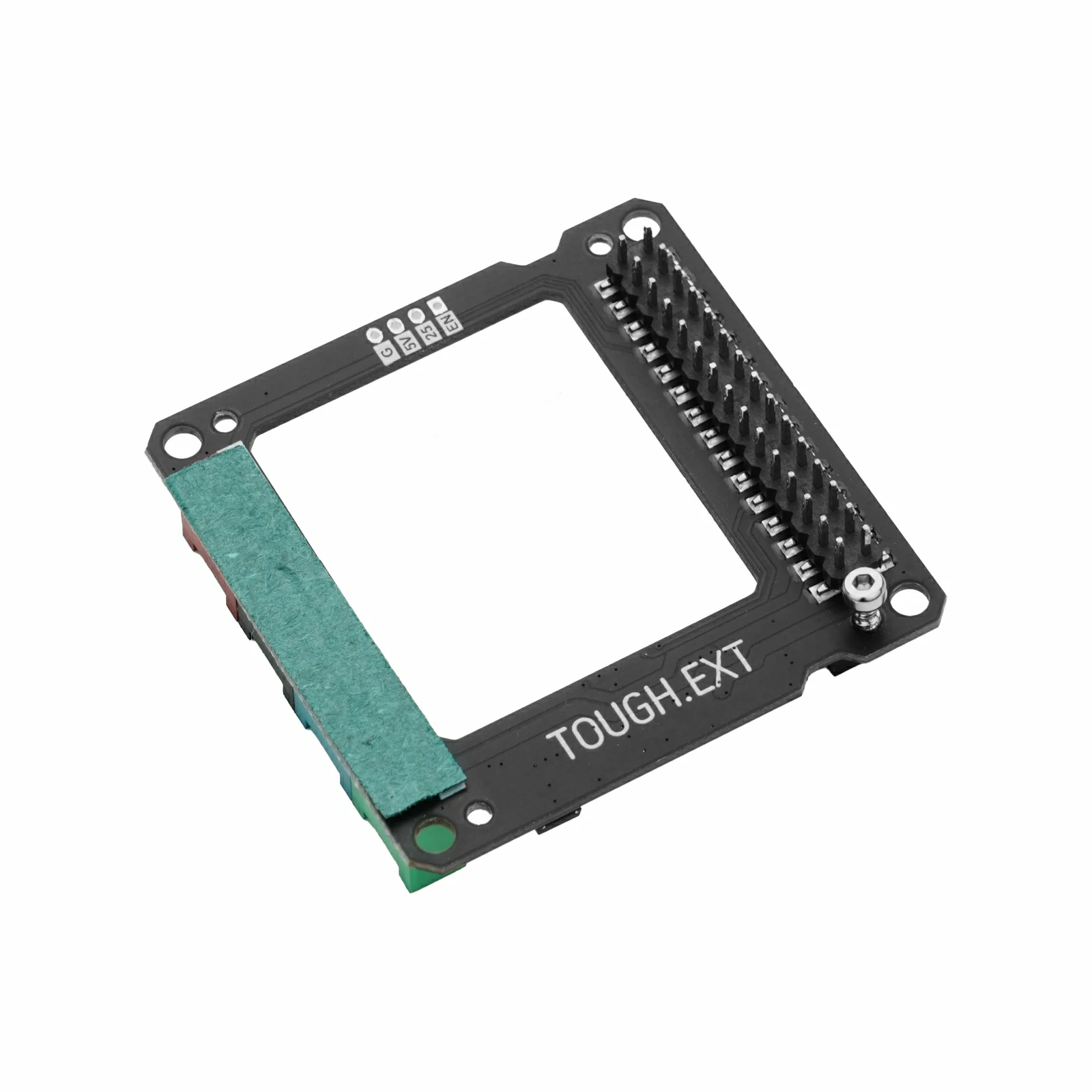
It integrates a 2.0" color LCD display (resolution 320 × 240) with a highly sensitive capacitive touch panel, and includes an onboard buzzer, microSD card slot, and RX8130CE real-time clock. The housing is made of PC + ABS (with UV powder), providing resistance to UV aging. Internally, the device offers I2C, GPIO, UART, and RS485 expansion interfaces as well as a battery connector, which are routed externally through the M12 connectors on both sides of the body for additional expansion. The system uses M5PM1 + M5IOE1 for multi-level power management and supports low-power wake-up. The device provides standard water and dust resistance (not designed for immersion), making it suitable for a wide range of applications such as outdoor edge data collection, smart buildings, and industrial gateways.
Shutdown state: DC 4.2V@10.41uA Full load state: DC 4.2V@320mA
Housing Material
PC + ABS (with UV powder)
Product Size
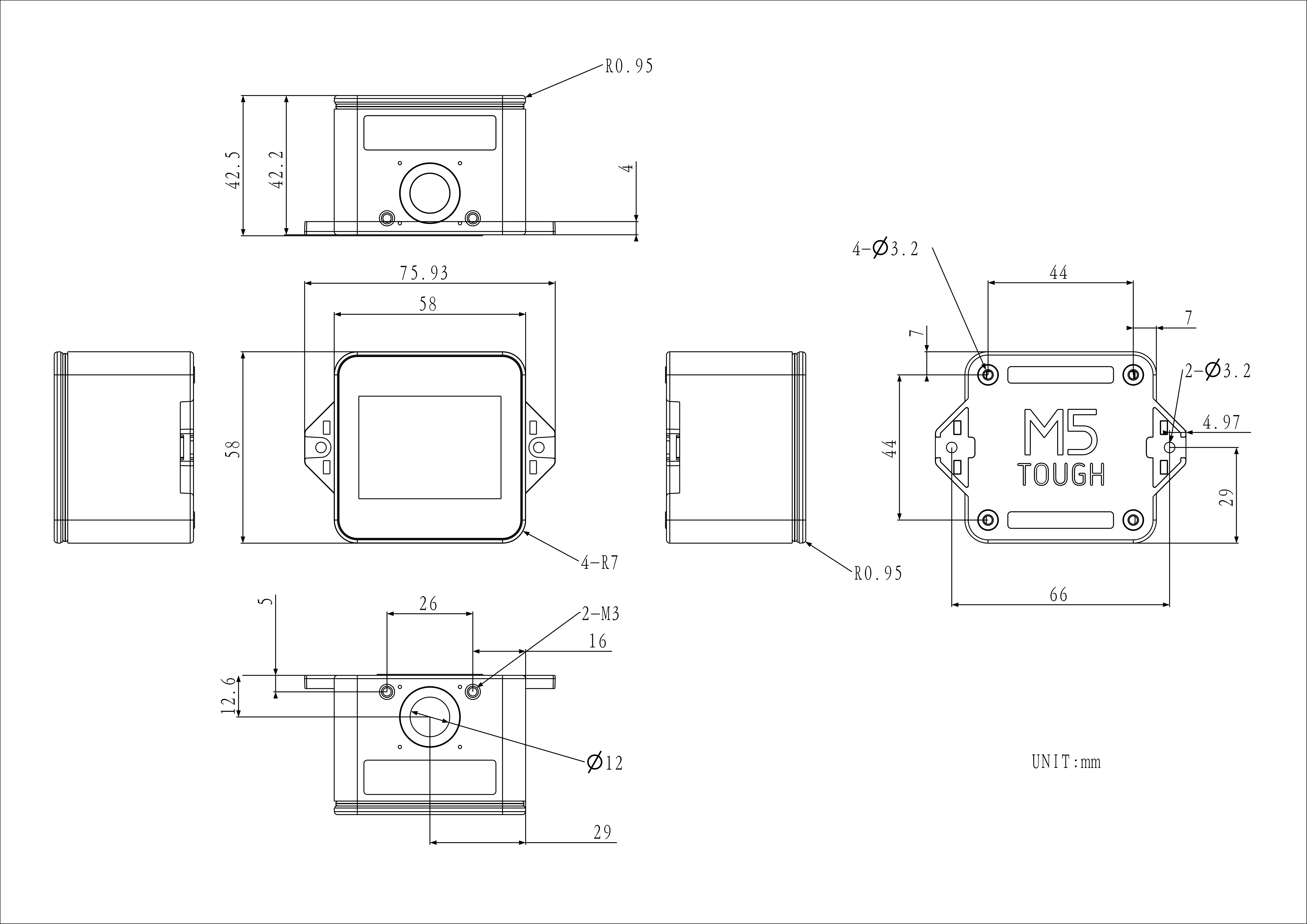
75.9 x 58.0 x 42.5mm
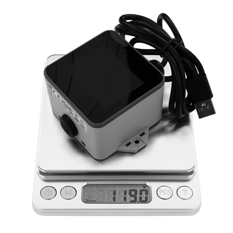
Product Weight
119.0g
Package Size
101.0 x 83.0 x 46.0mm
Gross Weight
161.4g
Learn
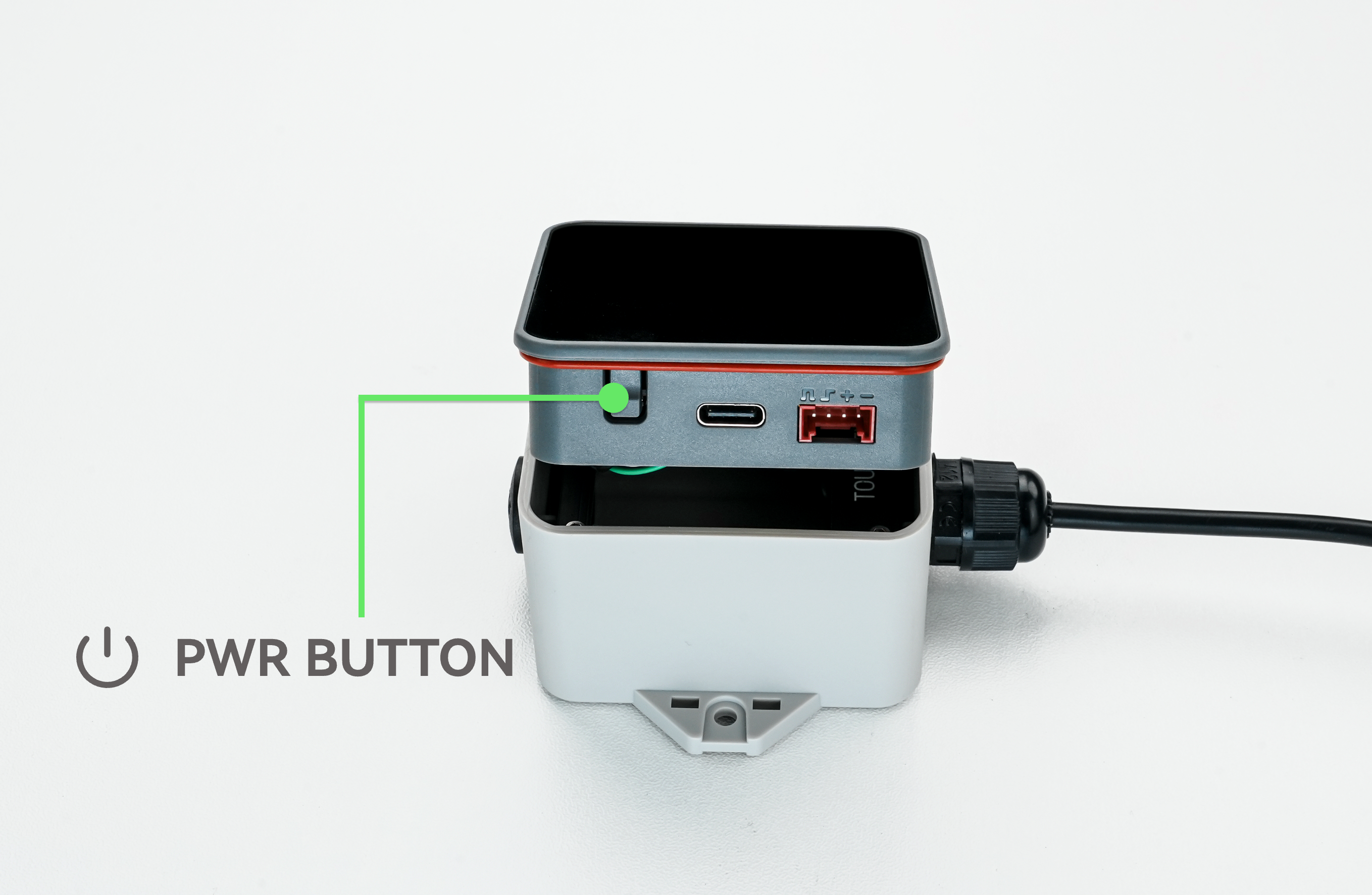
Button Operation
Enter Download Mode
Under normal circumstances, the device can be flashed with programs directly via the USB cable. During development and debugging, if an abnormal program flash occurs, the housing can be removed and the power button long-pressed to force entry into download mode.


The screen enable is controlled via PYG5 (PYB_LCD_EN) of the M5IOE1 expansion chip, and the screen reset is controlled via PYG4 (PYB_LCD_RST).
microSD
ESP32-C5HR8
G7
G8
G9
G10
microSD
MOSI
MISO
SCK
CS
The microSD card slot enable is controlled via PYG6 (PYB_TF_EN) of the M5IOE1 expansion chip, and PYG14 (PYB_TF_DET) detects the microSD card insertion status.
PYG14_PYB_TF_DET
Status
LOW
Inserted
HIGH
Not Inserted
Touch
ESP32-C5HR8
G2
G3
CHSC6540
SDA
SCL

The touch screen interrupt signal input is captured via PMG0 (PM_TP_INT) of the M5PM1 power management chip, and PYG2 (PM_TP_RST) controls the touch driver chip reset.
I2C Devices (TP & M5IOE1 & M5PM1)
ESP32-C5HR8
G2
G3
CHSC6540 (0x2E)
SDA
SCL
M5IOE1 (0x4F)
SDA
SCL
M5PM1 (0x6E)
SDA
SCL
RS485
ESP32-C5HR8
G23
G24
SP485EEN-L/TR
RS485_RX
RS485_TX
HY2.0-4P
HY2.0-4P
Black
Red
Yellow
White
PORT.A
GND
5V
G2
G3
PORT.B
GND
5V
G6
G1
PORT.C
GND
5V
G12
G11
PORT.RS485
GND
DC 6 ~ 24V INPUT
A
B
M5-Bus
FUNC
PIN
LEFT
RIGHT
PIN
FUNC
GND
1
2
G0
ADC
GND
3
4
G1
ADC
GND
5
6
RST
EN
MOSI
G7
7
8
G4
DAC
MISO
G8
9
10
G6
DAC
SCK
G9
11
12
3V3
RXD0
G12_PC_RX
13
14
G11_PC_TX
TXD0
RXD2
G12_PC_RX
15
16
G11_PC_TX
TXD2
Int SDA
G2
17
18
G3
Int SCL
PORT.A SDA
G2
19
20
G3
PORT.A SCL
GPIO
G23
21
22
G24
GPIO
GPIO
G27
23
24
G28
GPIO
NC
25
26
G5
GPIO
NC
27
28
5V
NC
29
30
BAT

M5PM1
M5PM1
PYG0
PYG1
PYG2
PYG3
PYG4
TOUCH
PM_TP_INT
PM_TP_RST
ESP32-C5HR8
PM_G1_IRQout
RTC
PM_RTC_INT
BUZZER
PM_BUZZER_EN
PYG0(PM_TP_INT): Touch screen interrupt wake-up signal
PYG1(PM_G1_IRQout): Interrupt output signal connected to ESP32-C5
PYG2(PM_TP_RST): Touch screen reset
PYG3(PM_RTC_INT): RTC interrupt wake-up signal
PYG4(PM_BUZZER_EN): Buzzer drive signal
M5IOE1
M5IOE1
PYG1
PYG3
PYG4
PYG5
PYG6
PYG10
PYG14
CHARGE
PYB_CHG_PROG
PYB_CHG_STAT
LCD
PYB_LCD_RST
PYB_LCD_EN
PYB_BL_EN
microSD
PYB_TF_EN
PYB_TF_DET
PYG1(PYB_CHG_PROG): Charge current control
PYG3(PYB_CHG_STAT): Charge status detection
PYG4(PYB_LCD_RST): LCD screen reset
PYG5(PYB_LCD_EN): LCD screen enable
PYG10(PYB_BL_EN): LCD screen backlight drive signal
PYG6(PYB_TF_EN): microSD card slot enable
PYG14(PYB_TF_DET): microSD card slot insertion status detection