FIRE v2.6
Tutorials & Quick Start
Select the development platform you want to use, view the corresponding tutorials & get started quickly.

FACES
Description
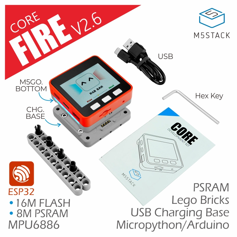
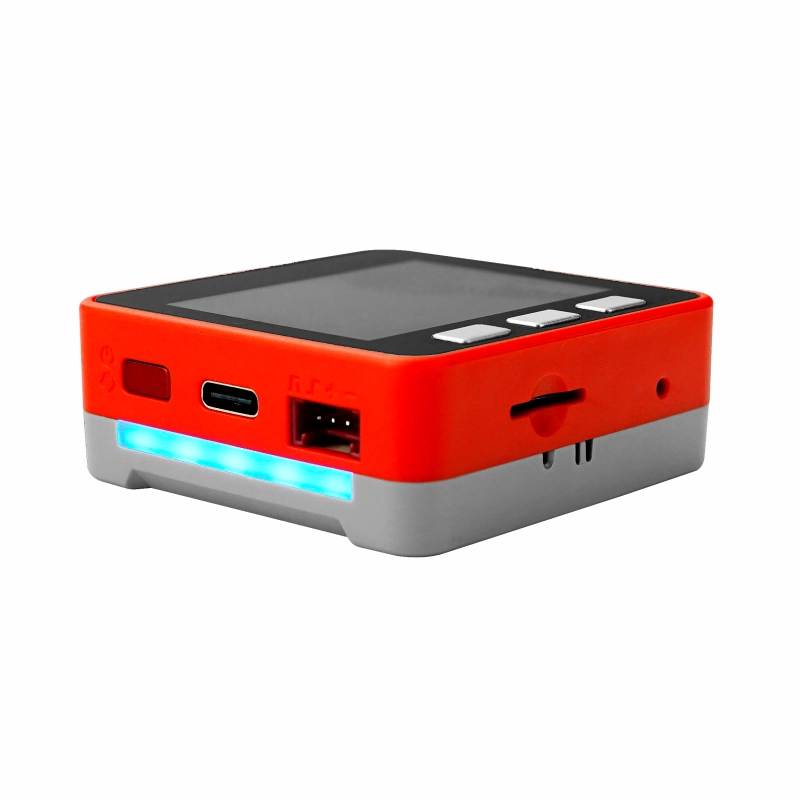
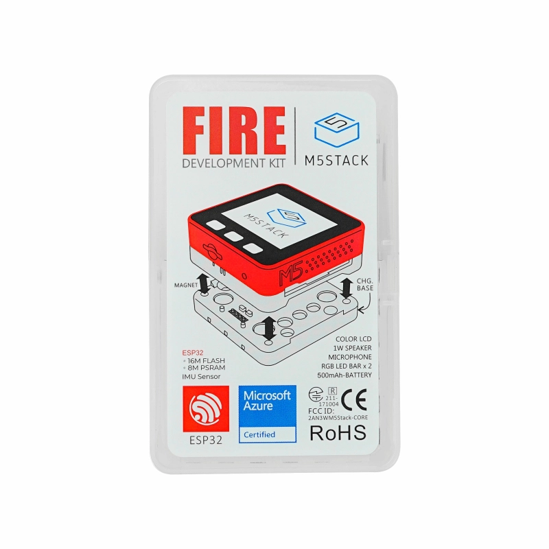
M5Stack FIRE It‘ a cost-effective Wi-Fi IoT controller adopts Espressif ESP32 main control chip, equipped with two low-power Xtensa® 32-bit LX6 microprocessors, with main frequency up to 240MHz. With 8M PSRAM + 16M FLASH memory, 2.0-inch full-color HD IPS display panel, IMU, LED, microphone, speaker, TFCard slot and other peripherals. The full-coverage case ensures circuit stability even in complex industrial applications. The internal offers a wide range of common interface resources (ADC/DAC/I2C/UART/SPI, etc.) which is highly expandable. This functional and powerful IoT controller is very applicable to various product prototyping, industrial control and smart building applications.
High productization.- Exquisite designs, Prototyping right into products
- Product-grade full-coverage cover for more stable circuit operation
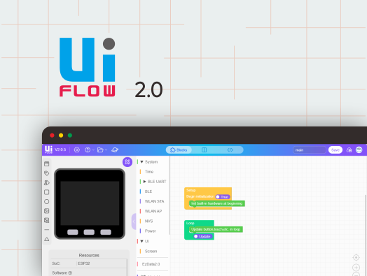
Low code development:- Support UIFlow graphical programming platform, scripting-free, cloud push
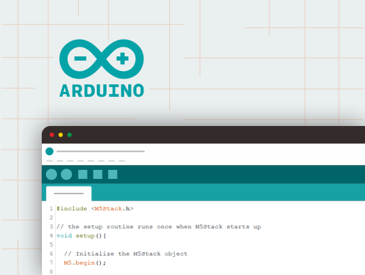
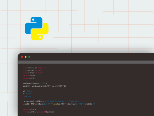
- Fully compatible with Arduino, ESP32-IDF and other mainstream development platforms
- Support FreeRTOS, with dual-core and multitasking mechanism, it can perform the tasks efficiently, Program optimization.
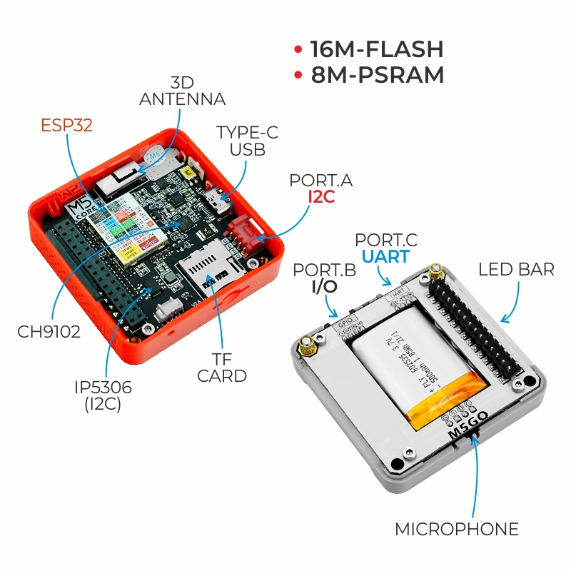
High integration.- 2.0-inch IPS display panel, 6-axis IMU, programmable RGB lights x10, microphone, speaker, custom buttons x3
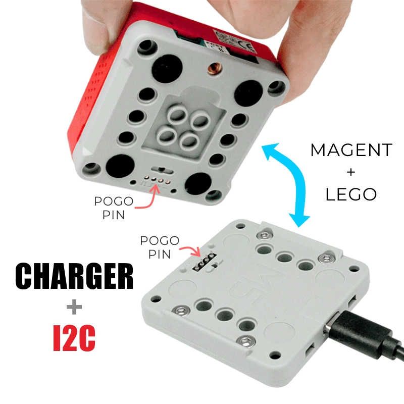
- Built-in Li-ion power, integrated power management chip, supports TypeC and POGO PIN
- finely tuned RF circuit for stable and reliable wireless communication
Strong expandability.- GROVE expansion ports x3 (I2C, GPIO, UART)
- Easy access to M5Stack software and hardware system, stackable module design, plug-and-play sensor expansion
GPIO 16 / 17 of FIRE are connected to PSRAM by default, so when you connect or stack other modules, you need to pay attention to avoid conflicts with these two pins to prevent the device from not working properly and generating instability..
Power on:Click the red button on the left
Power off: Quickly double-click the red button on the left
USB power: By default, It can not be shutdown when USB power is on.
Product Features
- Based on ESP32 development
- 8M PSRAM + 16M FLASH memory combination
- Integrated HD IPS display panel with various hardware peripherals
- Rich resources interface, compatible with M5Stack stacking modules and sensors, highly expandable.
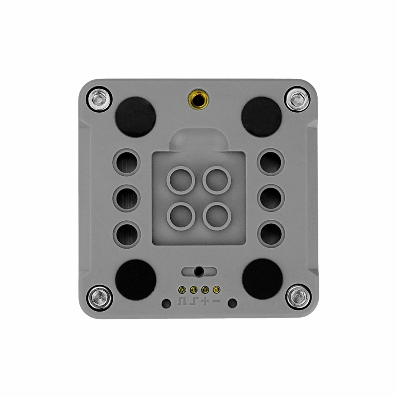
- Adopt M5GO BOTTOM base compatible with 8mm size LEGO blocks, the structure is full of fun to build.
- Microsoft Azure authentication device
- Compatible with multi-platform development:
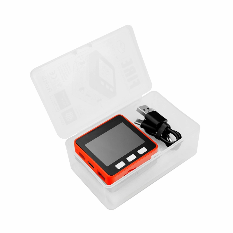
Included
- 1x M5Stack FIRE
- 1x M5GO Charging Base
- 2x LEGO Building Blocks
- 5x LEGO Connections
- 1x M3 Hex Wrench
- 1x Type-C USB (50cm)
- 1x User's Manual
Applications
- IoT Controller
- DIY creator works
- Smart Home Control
Specifications
| Specifications | Parameters |
|---|---|
| ESP32-D0WDQ6-V3 | 240MHz dual core, 600 DMIPS, 520KB SRAM, Wi-Fi |
| Flash | 16MB |
| PSRAM | 8MB |
| Input power | 5V @ 500mA |
| Interface | TypeC x1, POGO PIN x1, I2C x1, GPIO x1, UART x1 |
| Keys | Custom Keys x 3 |
| LCD screen | 2.0"@320*240 ILI9342C IPS panel, maximum brightness 853nit |
| Speaker | 1W-0928 |
| Microphone | Analog BSE3729 Microphone |
| IMU | 6-axis MPU6886 |
| USB Chip | CH9102F |
| LED | SK6812 RGB LED x 10 |
| Antenna | 2.4G 3D antenna |
| Battery - 500 mAh @ 3.7V | |
| Operating Temperature | 0°C to 40°C |
| Net Weight | 62.3g |
| Gross Weight | 162g |
| Product Dimensions | 54mm x 54mm x 30.5mm |
| Package Size | 105mm x 65mm x 40mm |
| Cover Material | Plastic ( PC ) |
Driver Installation
CP2104 version)/CP34X (for CH9102 version) driver compressed package. After decompressing the compressed package, select the installation package corresponding to the number of operating systems to install. (If you are not sure of the USB chip used by your device, you can install both drivers at the same time. During the installation process of CH9102_VCP_SER_MacOS v1.7, an error may occur, but the installation is actually completed, just ignore it.) When using it, if If the program cannot be downloaded normally (the prompt is overtime or Failed to write to target RAM), you can try to reinstall the device driver.| Driver name | Applicable driver chip | Download link |
|---|---|---|
| CP210x_VCP_Windows | CP2104 | Download |
| CP210x_VCP_MacOS | CP2104 | Download |
| CP210x_VCP_Linux | CP2104 | Download |
| CH9102_VCP_SER_Windows | CH9102 | Download |
| CH9102_VCP_SER_MacOS v1.7 | CH9102 | Download |
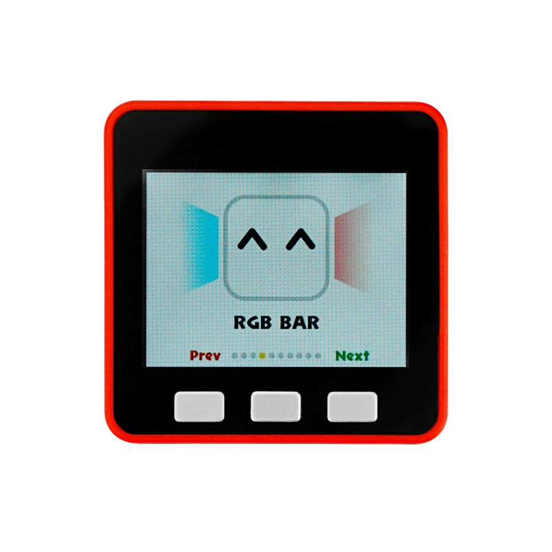
EasyLoader
EasyLoader It’s a simple yet fast program burner has built-in product-related case programs, which can be burned into the master control in simple steps to verify functional and performance
Load the UIFlow firmware, the built-in demo program supports accelerometer, LED BAR, microphone, keypad and some peripheral sensors testing, the firmware can be used for UIFlow graphical programming.
Pin Mapping
LCD screen & TF card
LCD Pixel: 320x240 TF card support up to 16GB
| ESP32 Chip | GPIO23 | GPIO19 | GPIO18 | GPIO14 | GPIO27 | GPIO33 | GPIO32 | GPIO4 |
|---|---|---|---|---|---|---|---|---|
| ILI9342C | MOSI/MISO | / | CLK | CS | DC | RST | BL | |
| TF Card | MOSI | MISO | CLK | CS |
Button & Speaker
| ESP32 Chip | GPIO39 | GPIO38 | GPIO37 | GPIO25 |
|---|---|---|---|---|
| Button Pins | BUTTON A | BUTTON B | BUTTON C | |
| Speakers | Speaker Pin |
GROVE Interface A & IP5306
The power management chip (IP5306) is a custom I2C version, and its I2C address is 0x75. Click here to view the IP5306's register manual.
| ESP32 Chip | GPIO22 | GPIO21 | 5V | GND |
|---|---|---|---|---|
| GROVE A | SCL | SDA | 5V | GND |
| IP5306 | SCL | SDA | 5V | GND |
IP5306 charge/discharge, voltage parameters
| Charging | Discharging |
|---|---|
| 0.00 ~ 3.40V -> 0% | 4.20 ~ 4.07V -> 100% |
| 3.40 ~ 3.61V -> 25% | 4.07 ~ 3.81V -> 75% |
| 3.61 ~ 3.88V -> 50% | 3.81 ~ 3.55V -> 50% |
| 3.88 ~ 4.12V -> 75% | 3.55 ~ 3.33V -> 25% |
| 4.12 ~ / -> 100% | 3.33 ~ 0.00V -> 0% |
MPU6886 3-axis accelerometer + 3-axis gyroscope
MPU6886 I2C address 0x68
| ESP32 Chip | GPIO22 | GPIO21 | 5V | GND |
|---|---|---|---|---|
| MPU6886 | SCL | SDA | 5V | GND |
M5GO Base Pins
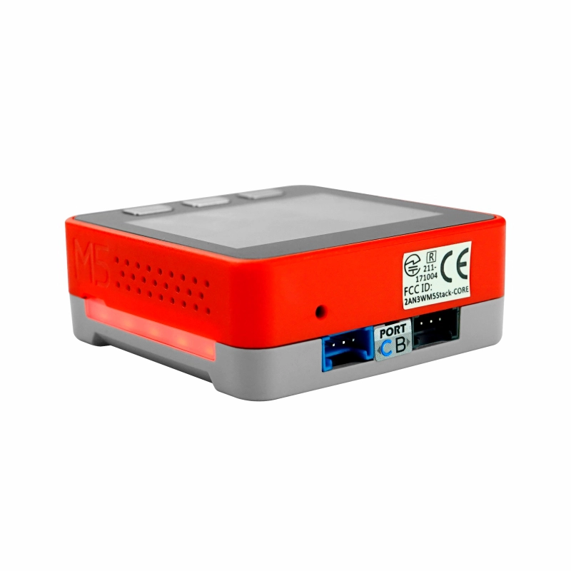
GROVE Interface B
| ESP32 Chip | GPIO36 | GPIO26 | 5V | GND |
|---|---|---|---|---|
| GROVE B | GPIO36 | GPIO26 | 5V | GND |
GROVE Interface C
| ESP32 Chip | GPIO16 | GPIO17 | 5V | GND |
|---|---|---|---|---|
| GROVE C | RXD | TXD | 5V | GND |
LED strip & microphone & speaker
| ESP32 Chip | GPIO15 | GPIO34 | GPIO25 |
|---|---|---|---|
| hardware | SIG Pin | MIC Pin | Speaker Pin |
M5 Port Description
| PORT | PIN | Note: |
|---|---|---|
| PORT-A(red) | G21/22 | I2C |
| PORT-B(black) | G26/36 | DAC/ADC |
| PORT-C(blue) | G16/17 | UART |
ESP32 ADC/DAC
M-BUS
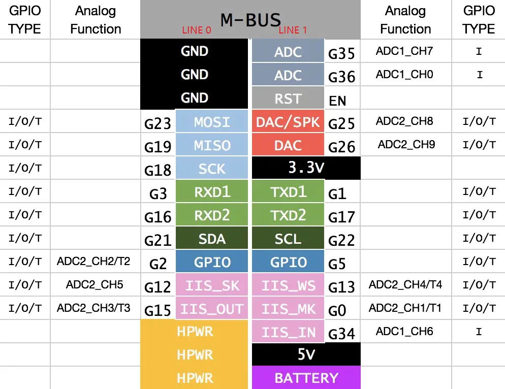
When use the RGB LEDs of GPIO15, we recommend initialize the pins Mode(15, OUTPUT_OPEN_DRAIN); For more info about pin assignment and pin remapping, please refer to ESP32 datasheet
Related Links
Schematics
Learn


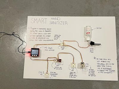

![SEAM [Safe-Entry Access Machine]](https://hackster.imgix.net/uploads/attachments/1255277/_zELd2Tpa8J.blob?auto=compress%2Cformat&w=400&h=300&fit=min)
Related Video
About M5Stack
Version Updates
| Release Date | Product Changes | Notes |
|---|---|---|
| 2018.6 | First Release | / |
| 2019.7 | MPU9250 changed to SH200Q+BMM150, TN screen changed to IPS screen | Please upgrade your M5Stack library to the latest version (v0.2.8 or above) to solve the screen reflection problem |
| 2019.8 | Change SH200Q to MPU6886 | / |
| 2019.11 | Battery capacity 600mAh changed to 500mAh | / |
| 2020.4 | PSRAM size changed from 4MB to 8MB | / |
| 2021.8 | Upgrade to v2.6: BMM150 magnetometer removed, CP2104 changed to CH9102, structure details optimized | / |
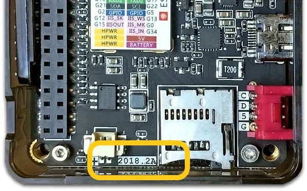
2018.2A PCB version of the device does not support C2C (TypeC to TypeC) connection and PD power supply.