
StamPLC IO
SKU:A176
Description
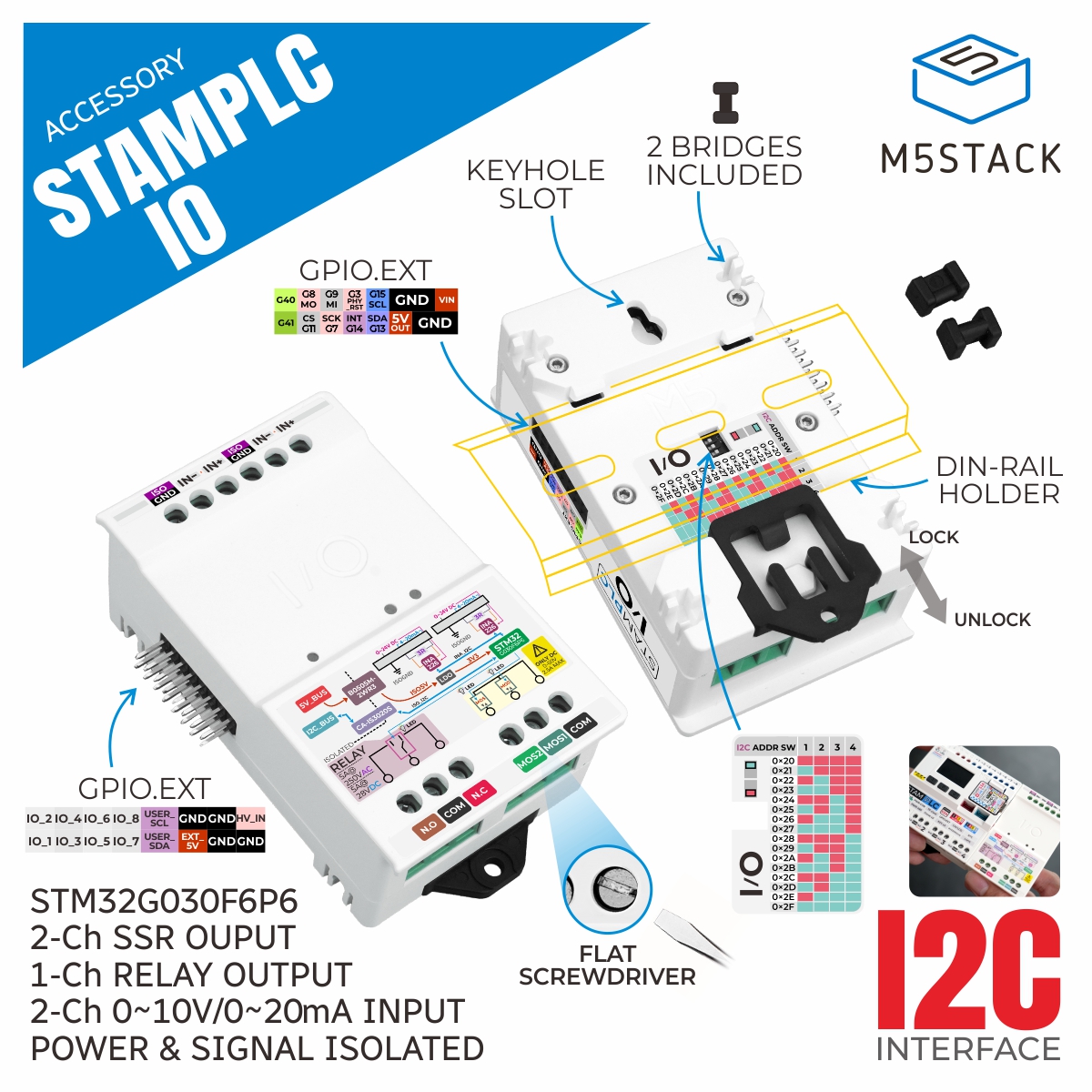
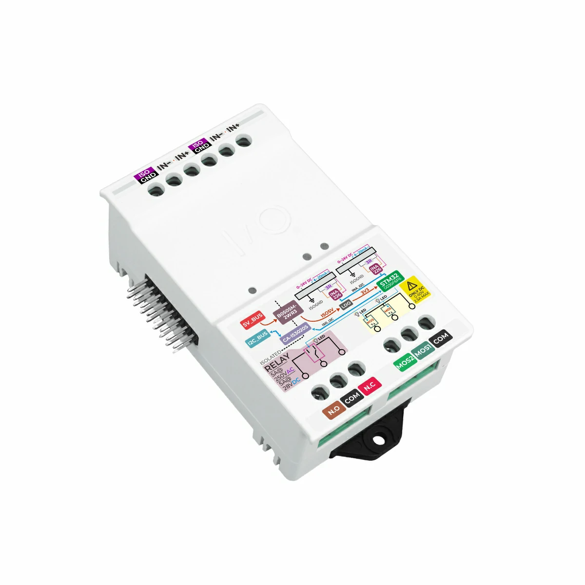
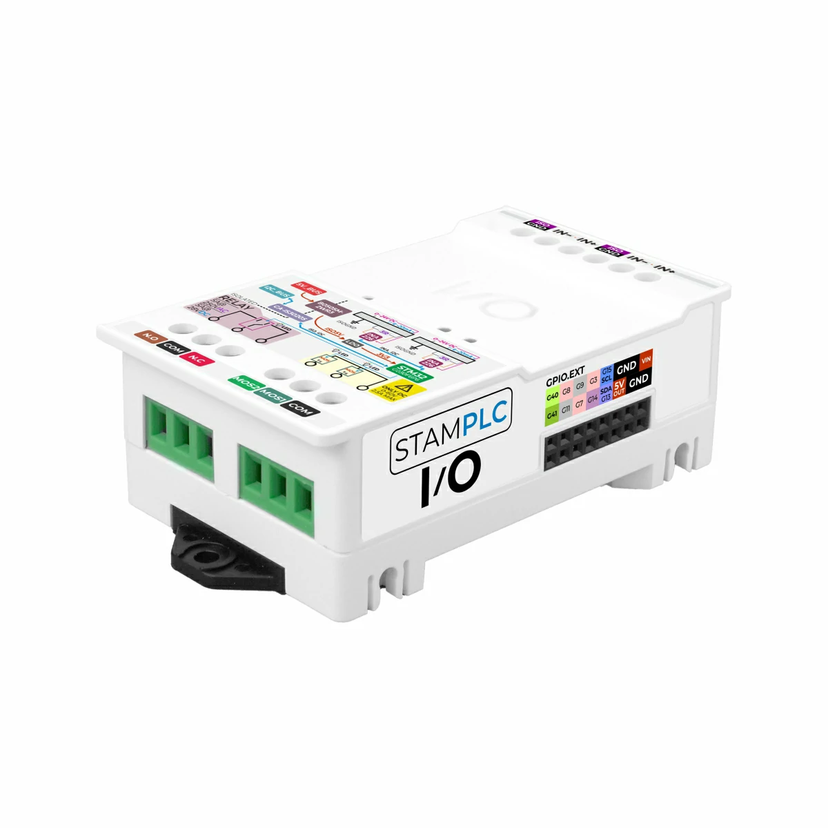
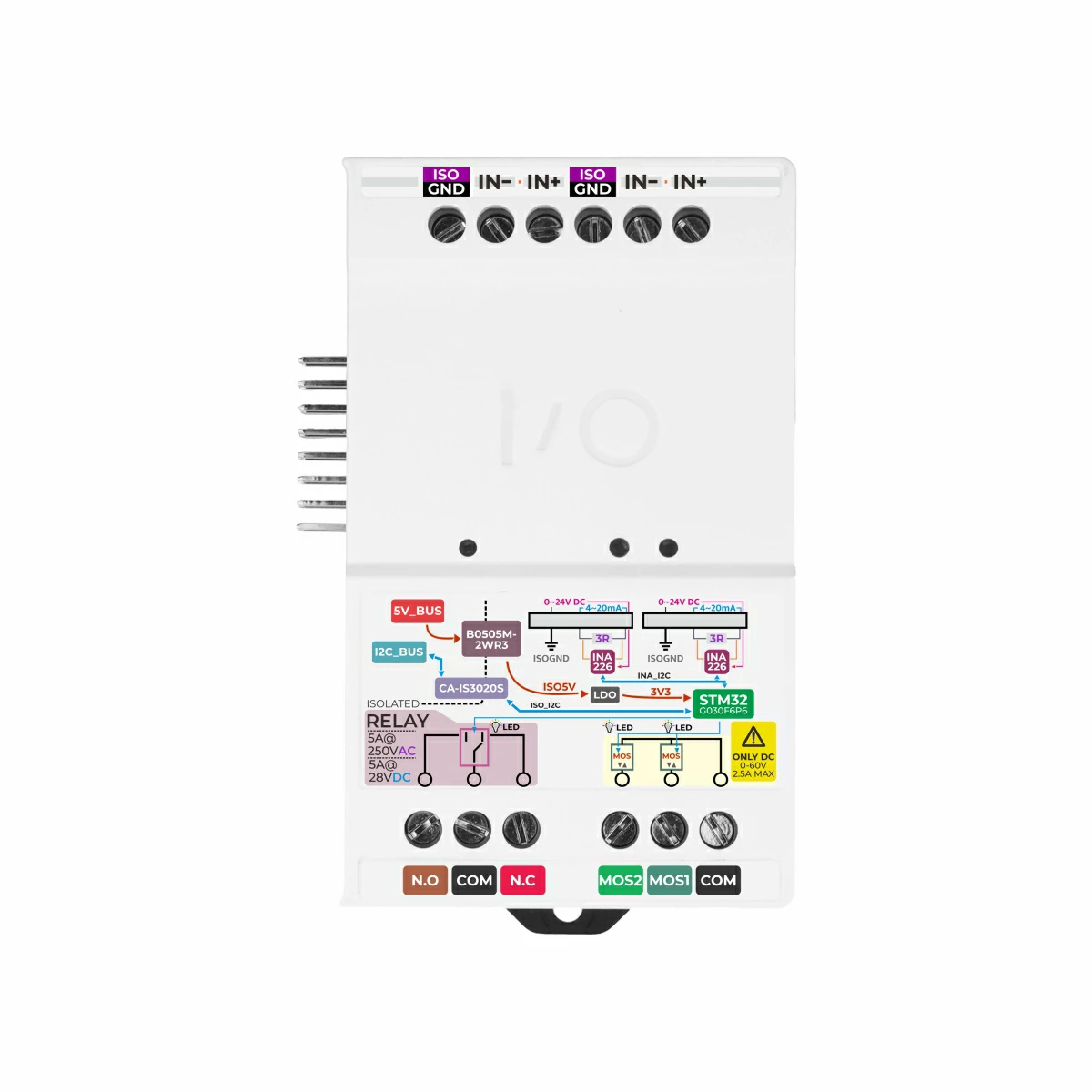
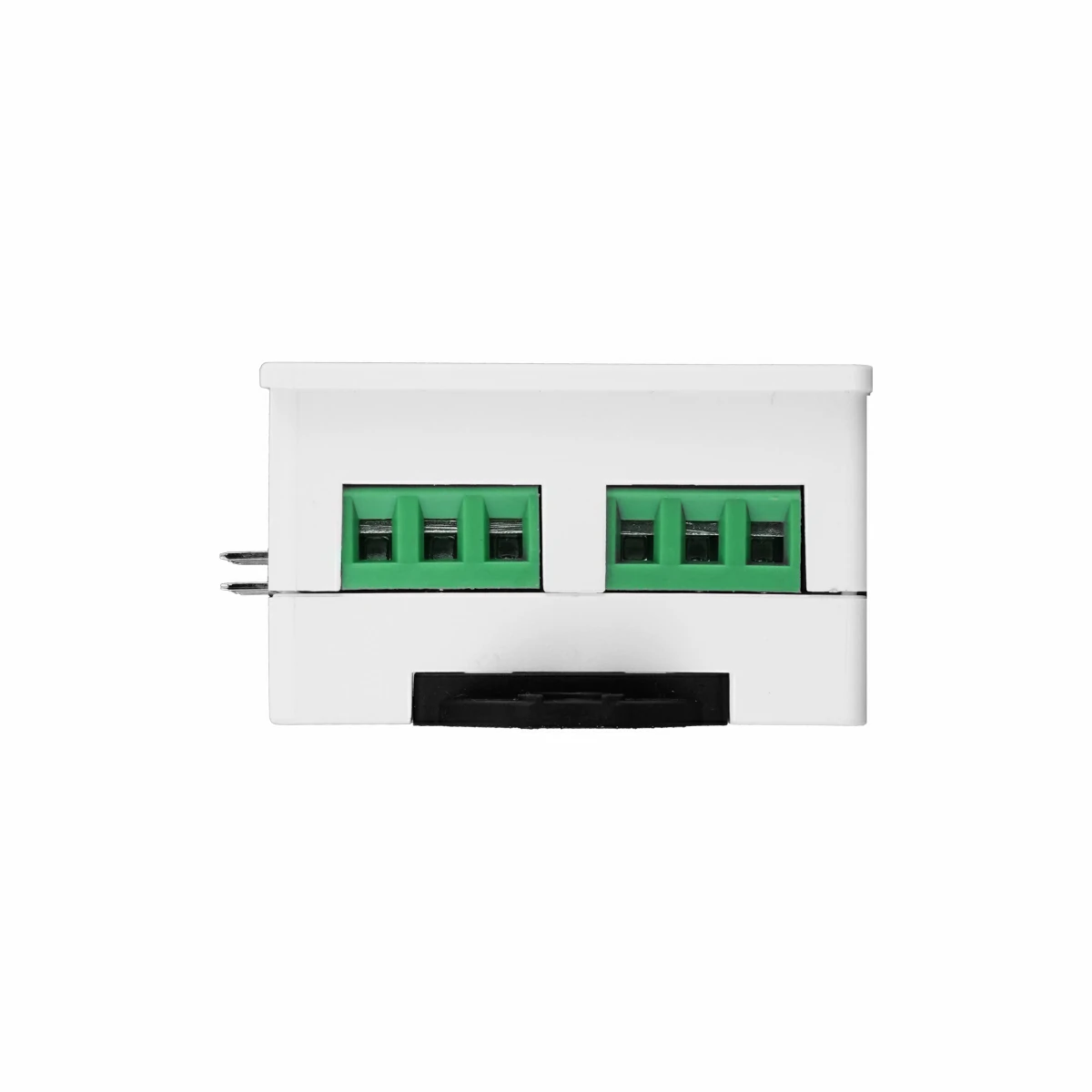
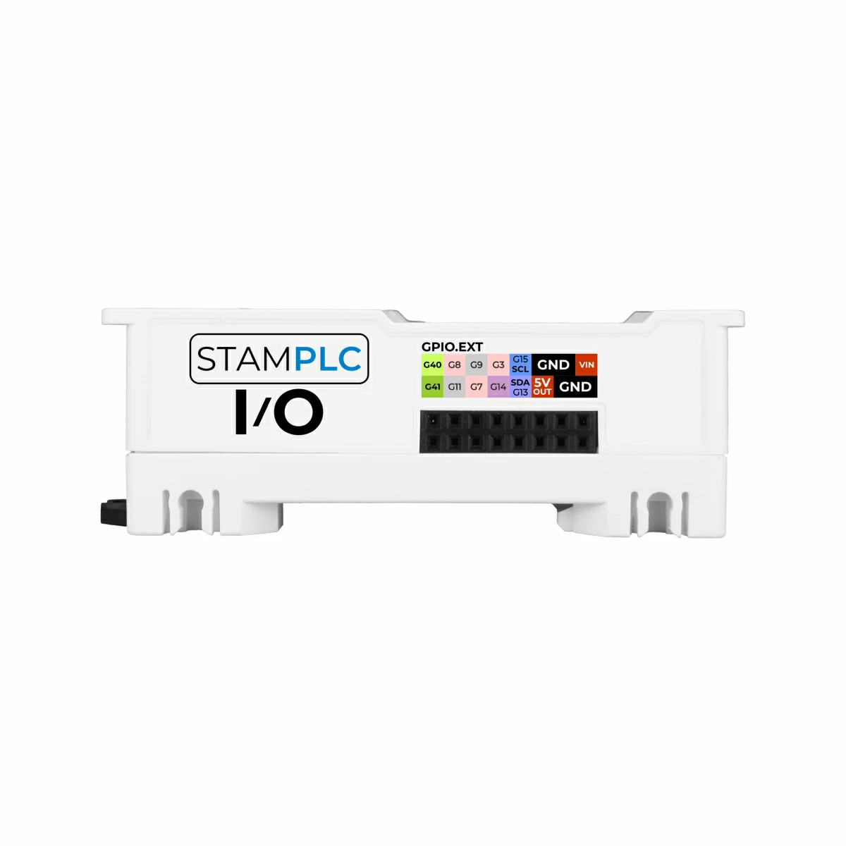
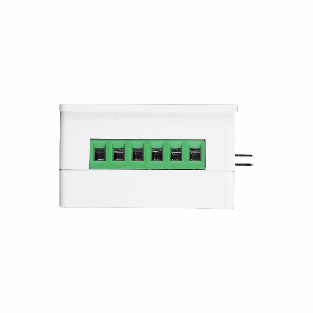
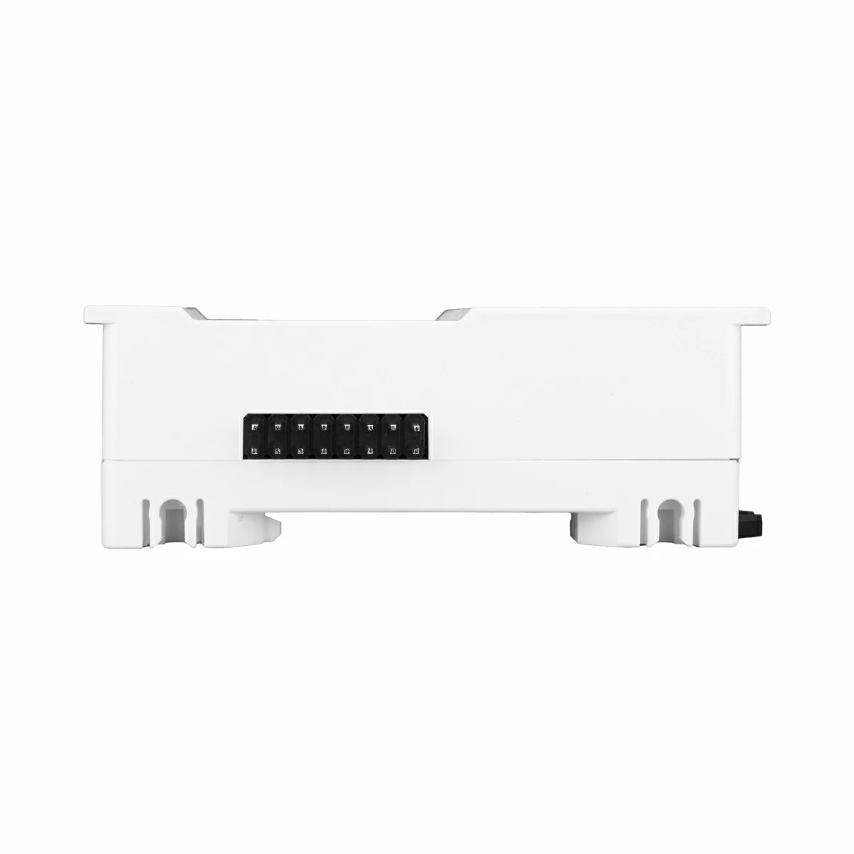
StamPLC IO is an electrically isolated IO expansion module designed for the StamPLC host and developed for industrial environments where high- and low-voltage circuits coexist. It provides two active analog acquisition channels, two solid-state relay outputs, and one mechanical relay output. The module supports signal acquisition from industrial active voltage and current sensors while controlling the on/off state of various load circuits. Its onboard STM32G030F6P6 main controller centrally manages external inputs and outputs, relay driving, address assignment, and I2C bus communication over the isolated channel. A hardware DIP switch allows the I2C address to be customized, enabling multiple modules to be connected in parallel or cascaded for flexible IO expansion.
The module integrates a CA-IS3020S digital isolator and B0505M-2WR3 isolated power module to provide complete electrical isolation between the communication bus and power circuit. This design effectively suppresses common-mode interference and surge impacts from sensors and field loads, significantly improving overall system stability. It is suitable for industrial automation applications such as power branch monitoring, low-voltage actuator driving, and sensor power management.
Features
- STM32G030F6P6 main controller
- I2C communication interface
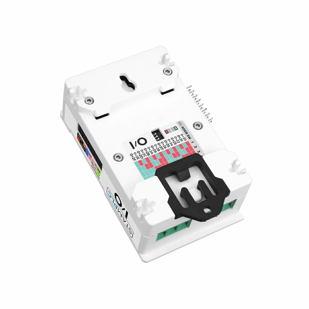
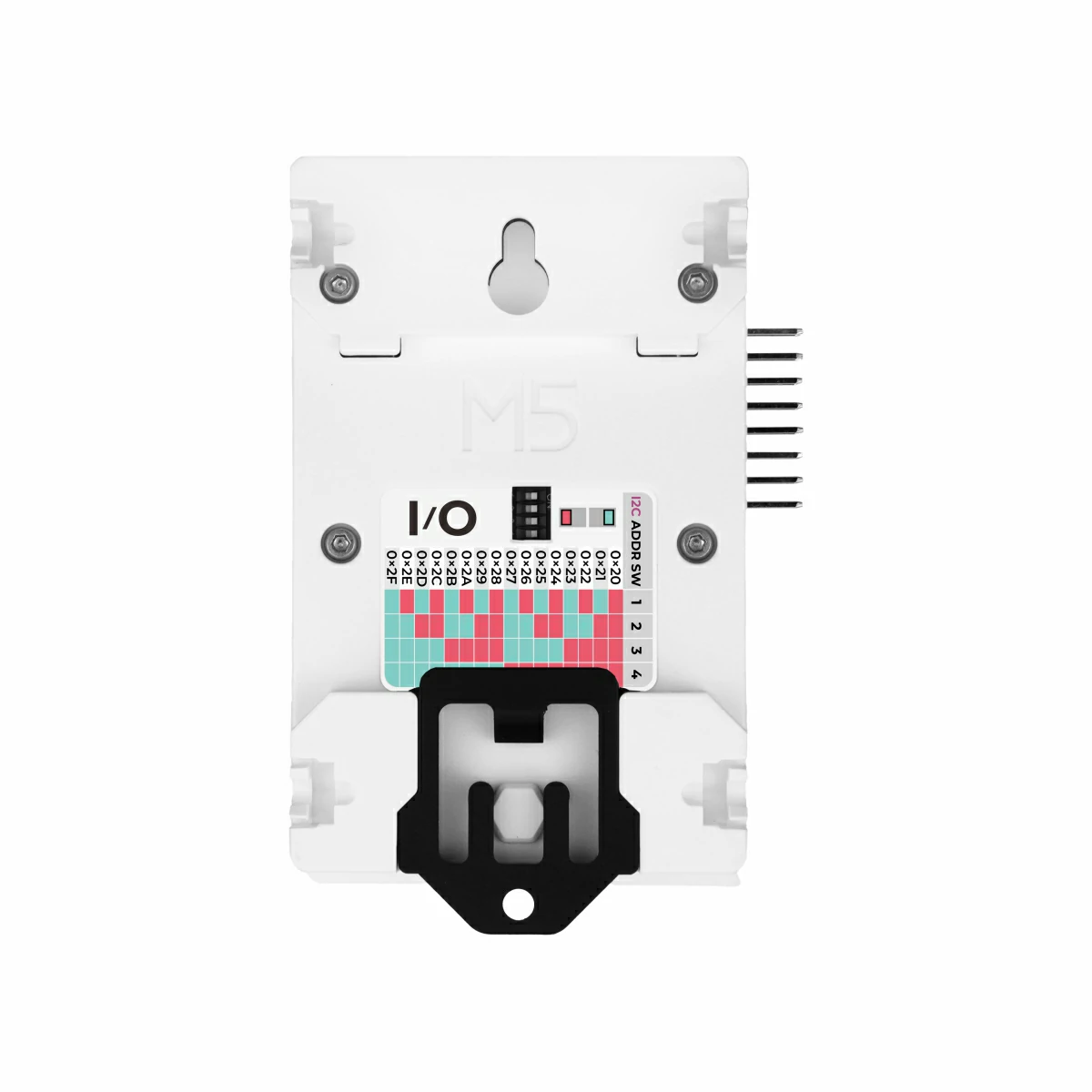
- Onboard 4-position DIP switch for configuring the device I2C address
- 2 active analog signal detection channels
- Supports DC 0 ~ 10V voltage-output sensors
- Supports 4 ~ 20mA current-output sensors
- 2 solid-state relay control channels
- Supports switching DC 0 ~ 60V MAX 2.5A circuits
- 1 mechanical relay control channel
- Supports switching AC 250V@5A / DC 28V@5A circuits
- Built-in CA-IS3020S I2C isolator
- Built-in B0505M-2WR3 isolated power module
- Onboard relay output status indicator LEDs
- Protection circuits on input and output channels
- DIN rail mounting / mounting-hole installation
Includes
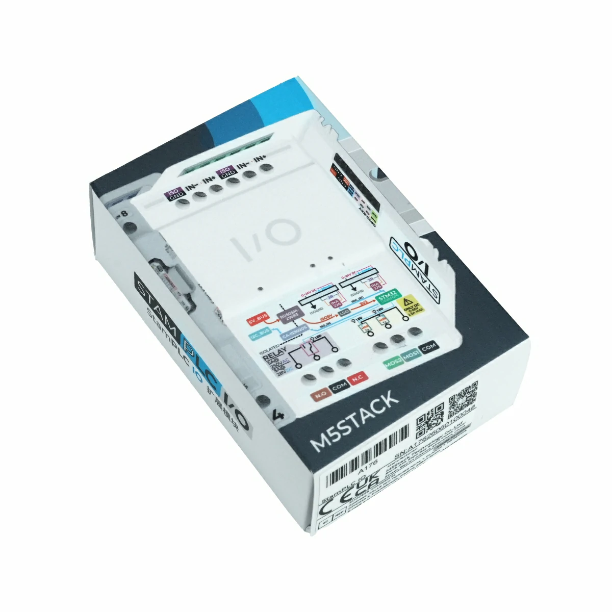
- 1 x StamPLC IO
- 2 x Mounting Bracket
Applications
- General-purpose analog signal acquisition
- External actuator switch control
- Remote control of relay dry contacts
- Multi-module isolated IO expansion
Specifications
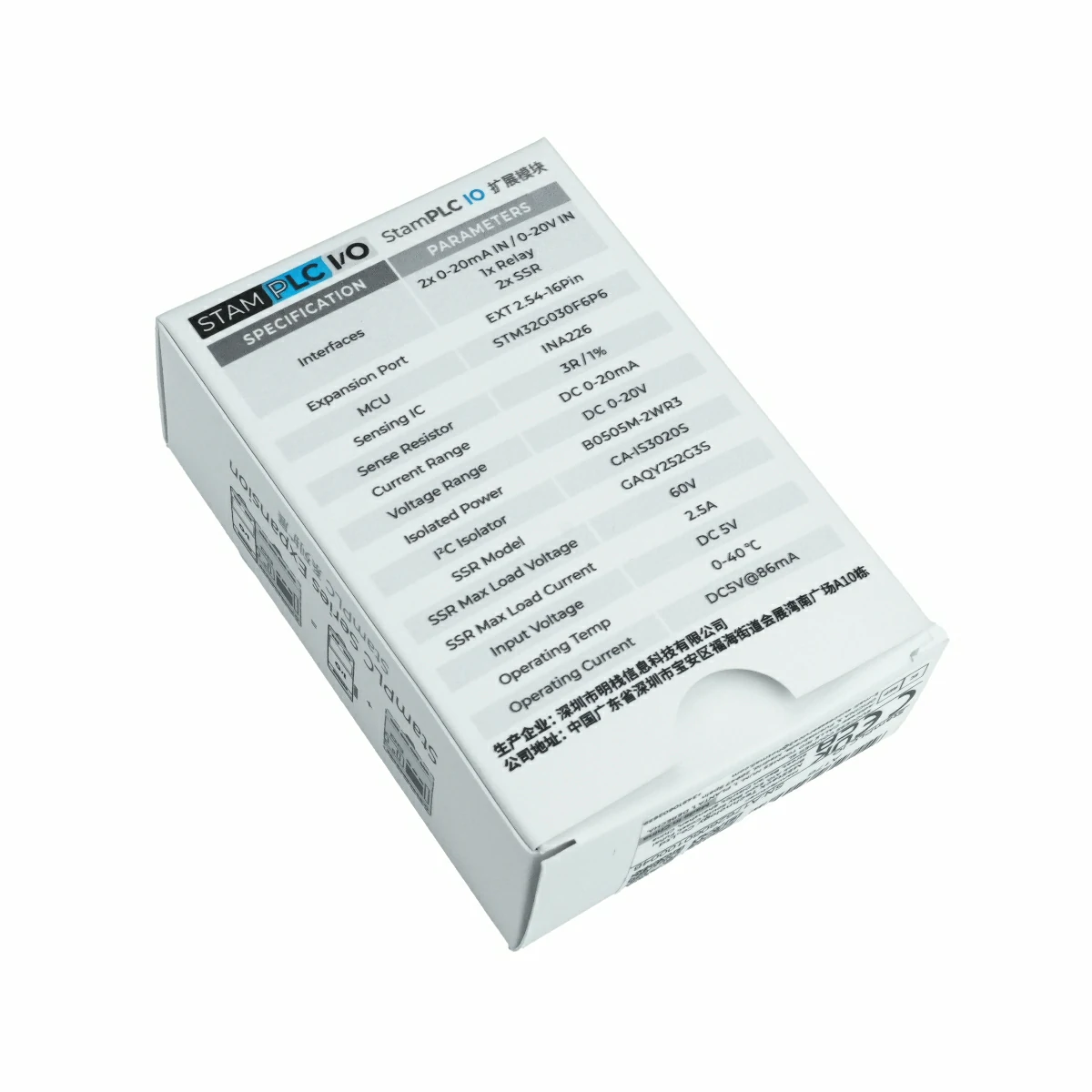
| Specification | Parameter |
|---|---|
| MCU | STM32G030F6P6 |
| Communication | I2C @ 0x20 |
| I2C Isolator | CA-IS3020S |
| Isolated Power Module | B0505M-2WR3 |
| Power Conversion | TPAP7343D-33FS4 |
| Voltage / Current Monitor | INA226AIDGSR |
| Detection Channels | 2 analog signal detection channels (compatible with 4 ~ 20mA and 0 ~ 10V analog acquisition) |
| MOS Switch Output | 2 solid-state relay outputs, MOS1 / MOS2, common terminal COM, supporting DC 0 ~ 60V MAX 2.5A switching |
| Relay Output | 1 SRD-5VDC-SL-C mechanical relay, N.C / COM / N.O terminals, supporting AC 250V@5A / DC 28V@5A switching |
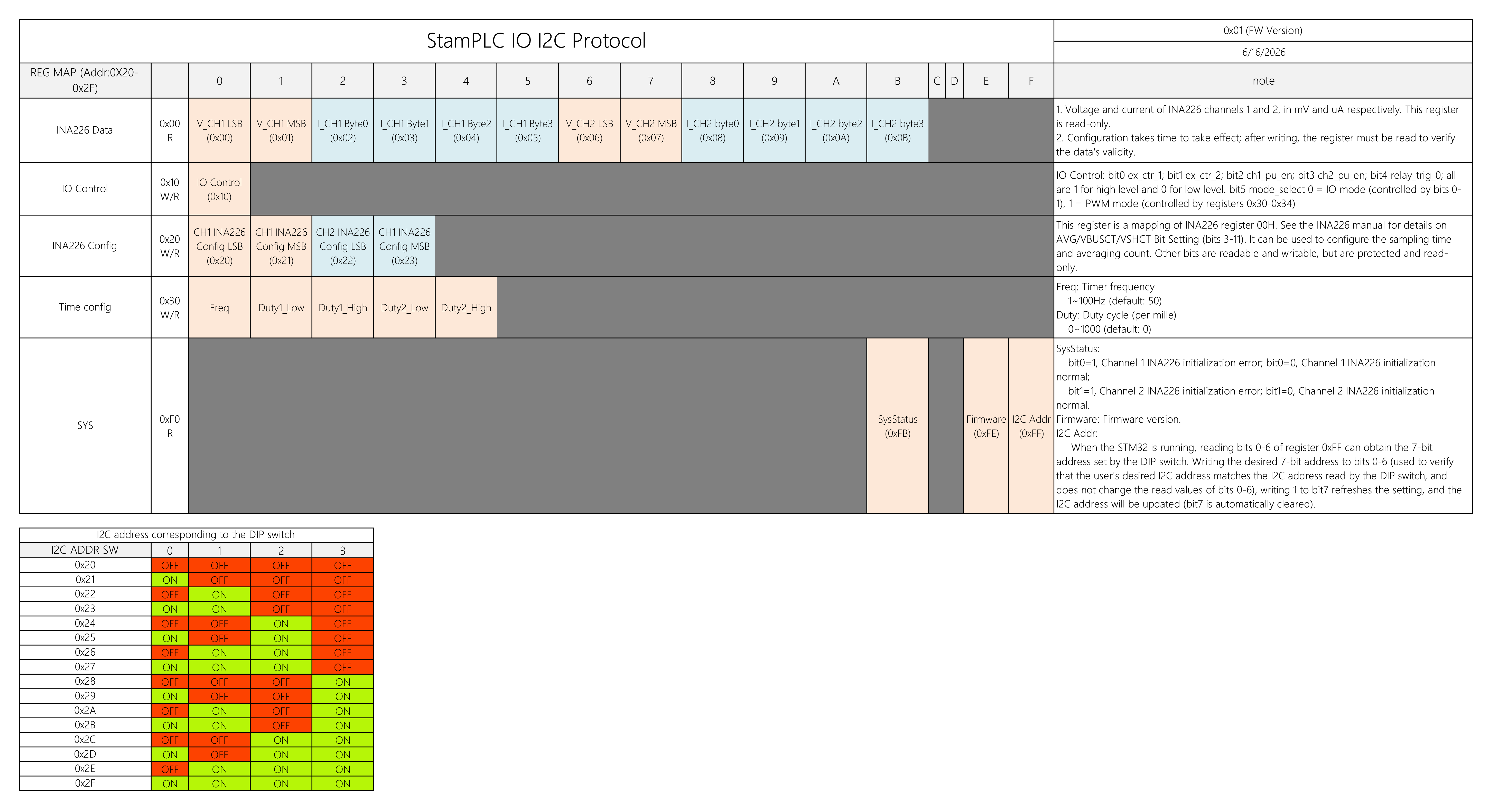
| Address Configuration | 4-position DIP switch, configurable I2C address range: 0x20 ~ 0x2F |
| Control Interface Type | 2 x 3P switch output / relay terminals, 1 x 6P input terminal |
| Installation | DIN rail mounting / mounting hole |
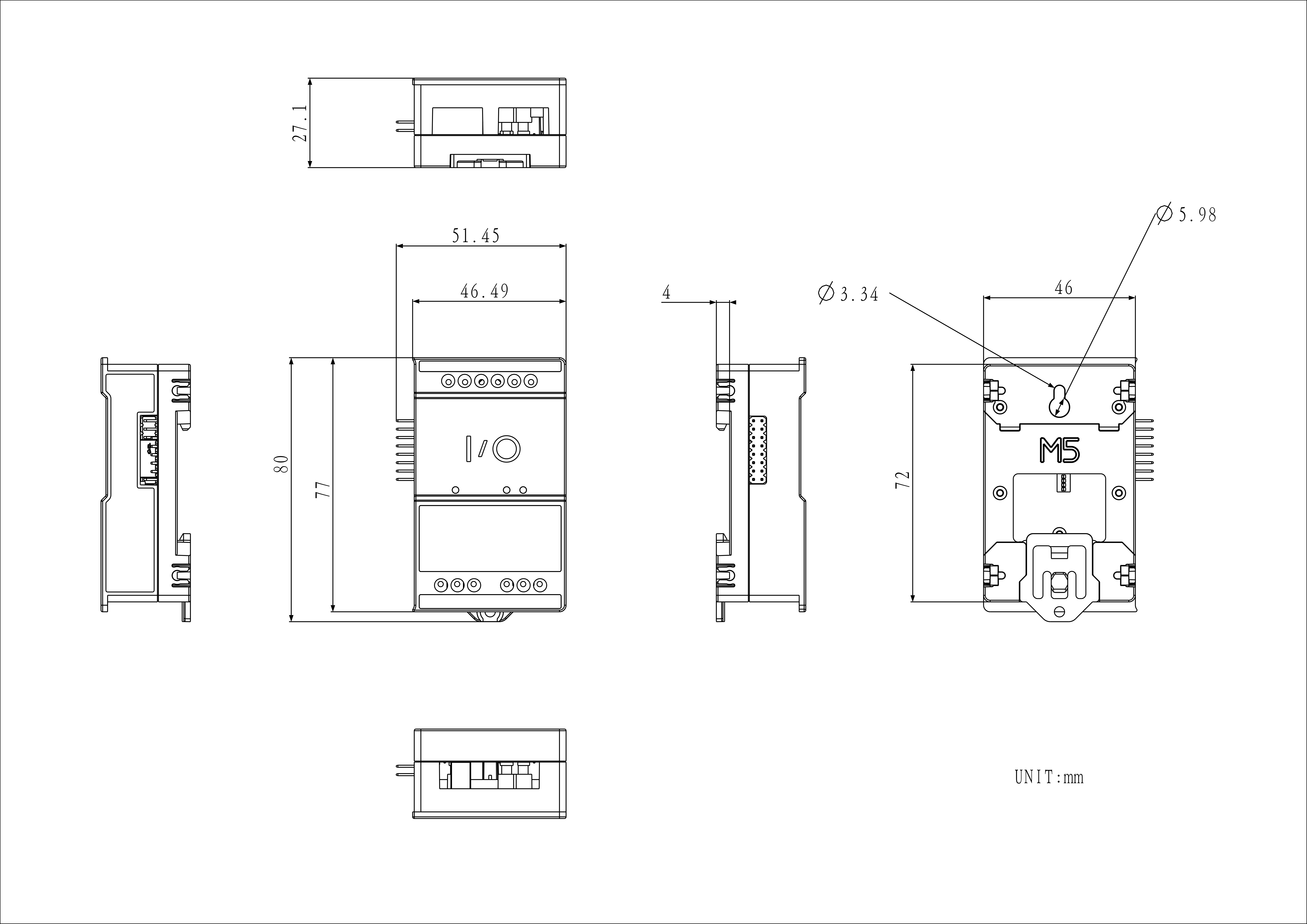
| Product Size | 51.4 x 80.0 x 27.1mm |
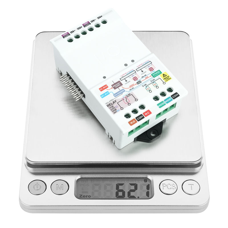
| Product Weight | 62.1g |
| Package Size | 84.0 x 56.0 x 29.0mm |
| Gross Weight | 69.2g |
Learn
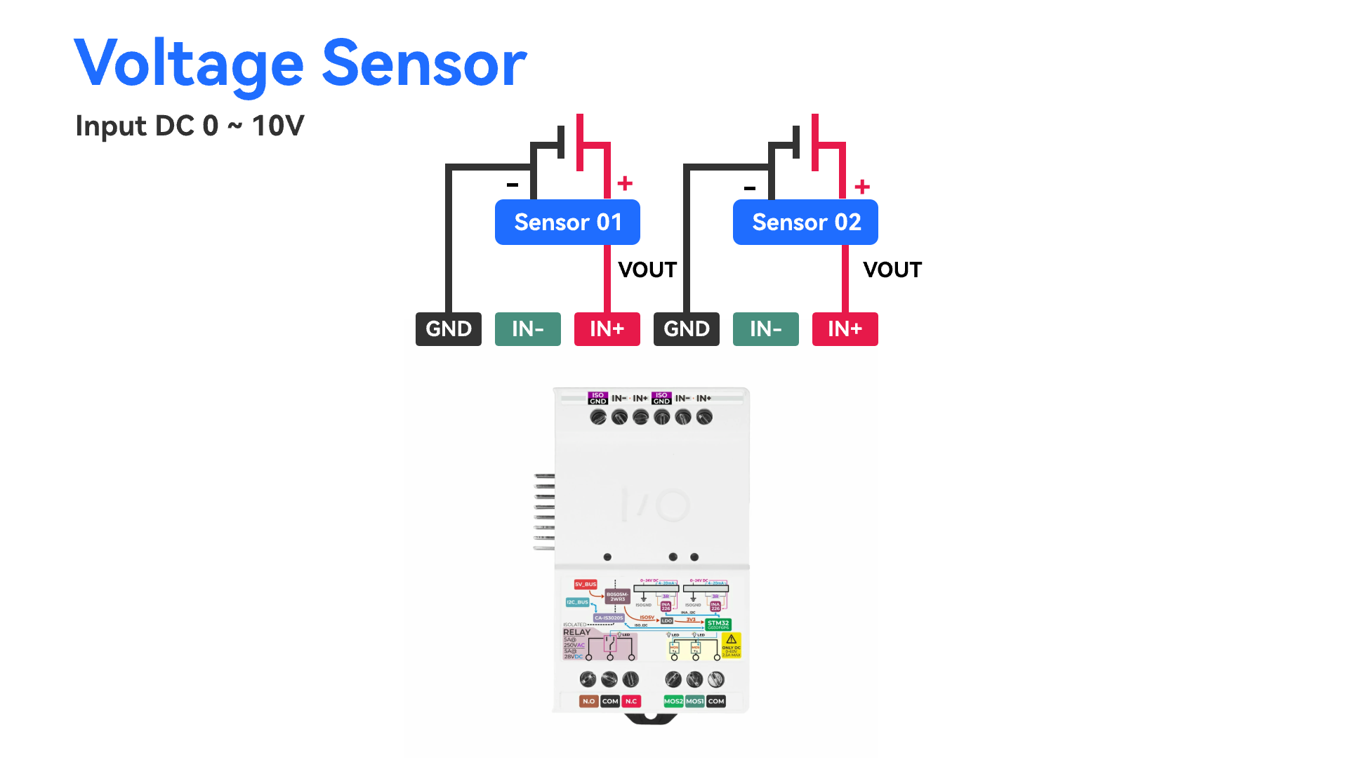
Voltage Sensor Wiring
- To measure voltage, connect an active device under test to the IN+ and ISO GND terminals of an input detection channel, as shown below:
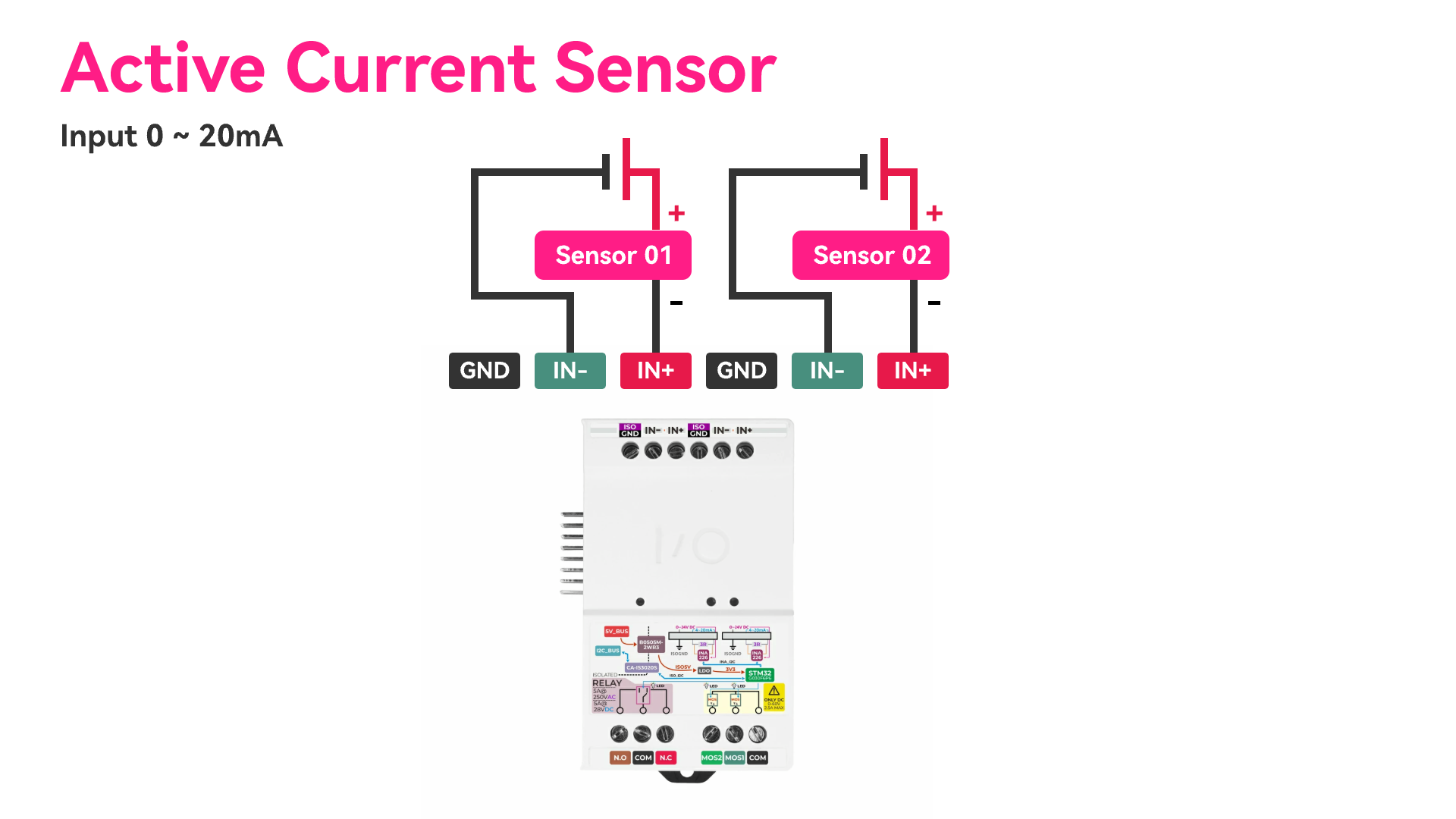
Current Sensor Wiring
- To measure current, connect an active device under test to the IN+ and IN- terminals of an input detection channel, as shown below:
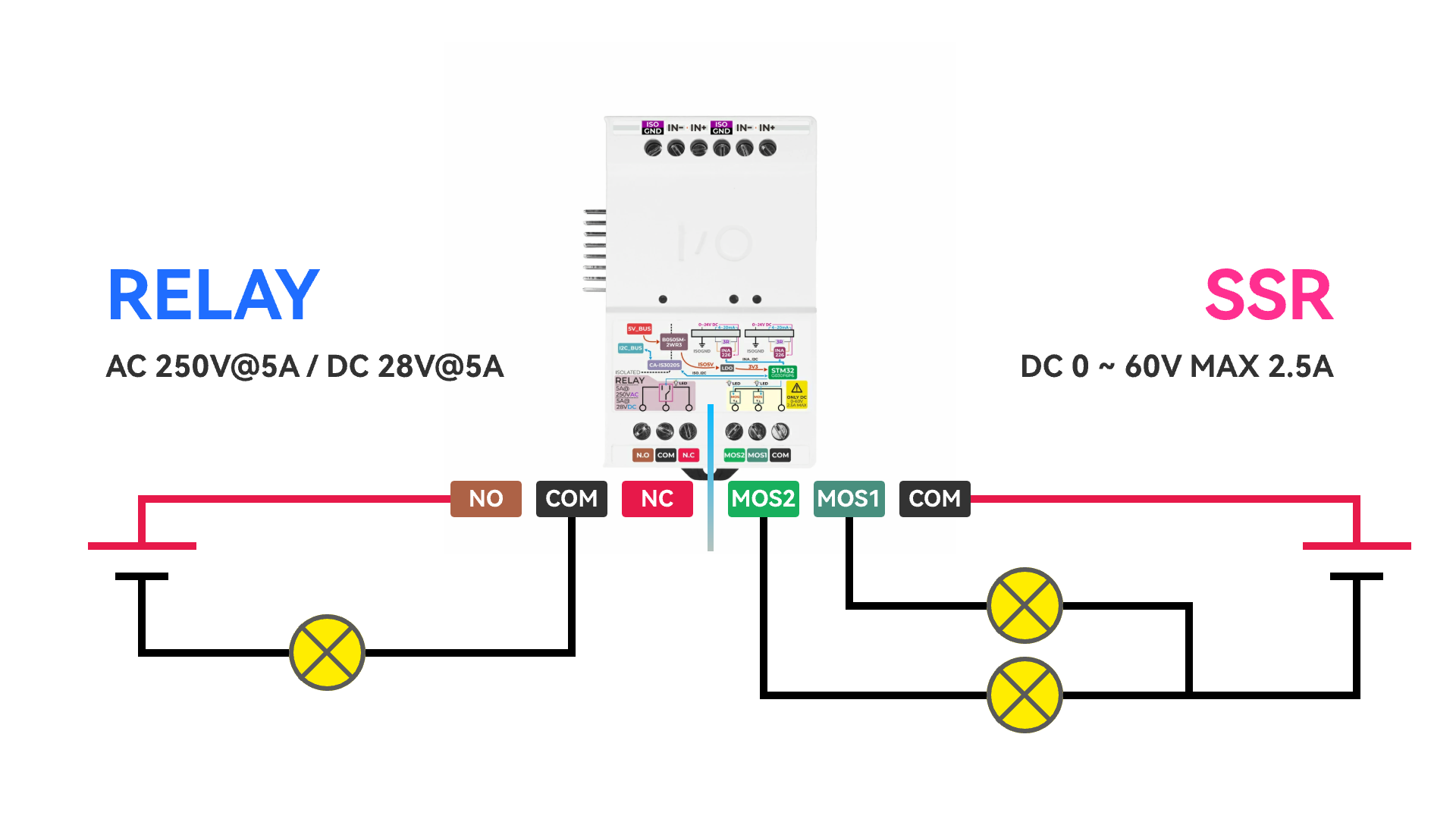
Relay Switch Wiring
- The mechanical relay output provides N.C / COM / N.O terminals, while the solid-state relay output provides MOS1 / MOS2 / COM terminals. The wiring is shown below:
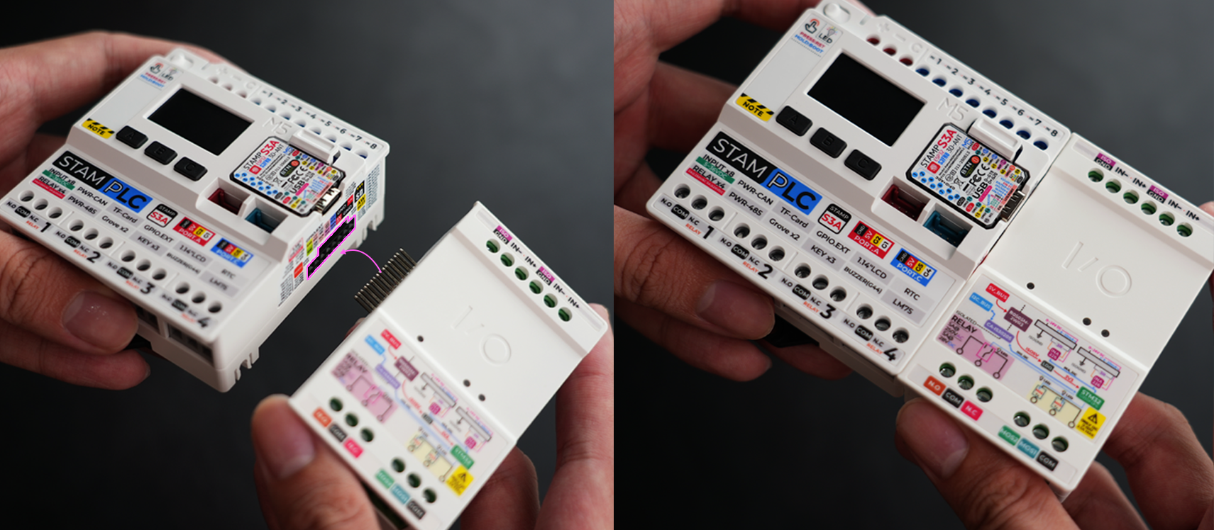
StamPLC and StamPLC IO Connection Diagram
Schematics


PinMap
| StamPLC | G15 | G13 |
|---|---|---|
| StamPLC IO | SCL | SDA |
StamPLC-Bus
| PIN | LEFT | RIGHT | PIN |
|---|---|---|---|
| IO_1 | 1 | 2 | IO_2 |
| IO_3 | 3 | 4 | IO_4 |
| IO_5 | 5 | 6 | IO_6 |
| IO_7 | 7 | 8 | IO_8 |
| USER_SDA | 9 | 10 | USER_SCL |
| EXT_5V | 11 | 12 | GND |
| GND | 13 | 14 | GND |
| GND | 15 | 16 | HV_IN |
Model Size
Datasheets
Softwares
Arduino
Internal Firmware
Protocol
Video
- StamPLC IO Product Introduction and Feature Demonstration