Arduino Quick Start
2. Devices & Examples
3. M5Unified
4. M5GFX
5. Extensions
Unit
Module
Atomic
Tab5
IoT
Accessories
StamPLC IO Arduino Tutorial
1. Preparation
Environment setup: Refer to Getting Started with Arduino IDE to complete the IDE installation, and install the corresponding board manager and required driver libraries according to your development board.
Required libraries:
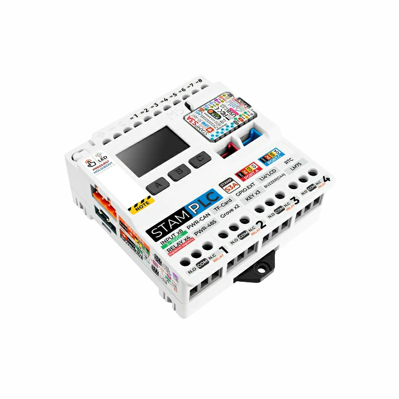
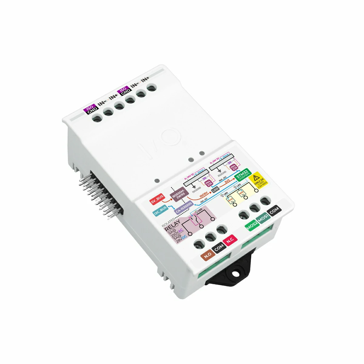
Required hardware products:
2. Example Program
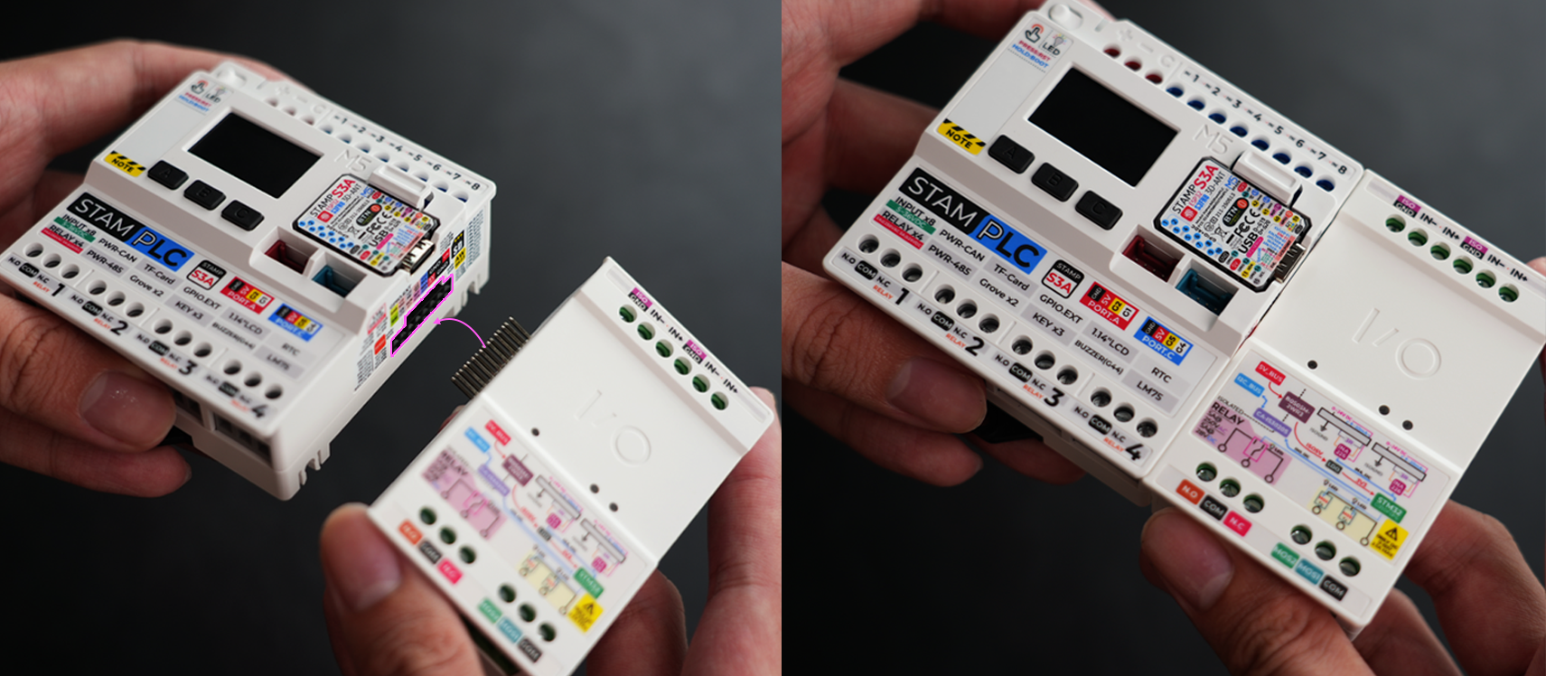
- In this tutorial, the main controller used is StamPLC, paired with StamPLC IO. StamPLC IO communicates with the host via I2C. Please modify the pin definitions in the program according to your actual circuit connection. After connecting the devices, the corresponding I2C IO are
G15 (SCL)andG13 (SDA).
The physical connection and assembly are shown below:
Voltage/Current Detection
#include <M5StamPLC.h>

M5Canvas canvas(&M5StamPLC.Display());
M5StamPLC_IO stamplc_io;

constexpr uint32_t MONITOR_UPDATE_INTERVAL_MS = 500;

void setup()
{
    M5StamPLC.begin();
    canvas.createSprite(M5StamPLC.Display().width(), M5StamPLC.Display().height());
    canvas.setTextScroll(false);
    canvas.fillScreen(TFT_BLACK);
    canvas.setTextSize(1);
    canvas.setFont(&fonts::efontCN_16);
    canvas.println("Try to find M5StamPLC IO");

    while (!stamplc_io.begin()) {
        canvas.println("M5StamPLC_IO not found, retry in 1s...");
        canvas.pushSprite(0, 0);
        delay(1000);
    }

    canvas.printf("Found: 0x%02X  FW: 0x%02X\n", stamplc_io.getCurrentAddress(), stamplc_io.getFirmwareVersion());
    canvas.println("Start monitoring...");
    canvas.pushSprite(0, 0);
}

void loop()
{
    M5StamPLC.update();

    static uint32_t last_update = 0;
    bool need_update           = stamplc_io.syncAddress();
    uint32_t now               = millis();

    if (now - last_update >= MONITOR_UPDATE_INTERVAL_MS || need_update) {
        last_update = now;

        int16_t v1, v2;
        int32_t i1, i2;
        stamplc_io.readAllChannelsData(&v1, &i1, &v2, &i2);

        uint8_t io_ctrl    = stamplc_io.readRegister(M5StamPLC_IO::REG_IO_CONTROL);
        uint8_t sys_status = stamplc_io.getSystemStatus();

        canvas.fillScreen(TFT_BLACK);
        canvas.setCursor(0, 0);

        canvas.setTextColor(TFT_GREENYELLOW);
        canvas.println("== Voltage/Current Monitor ==");
        canvas.println();

        canvas.setTextColor(sys_status & (1 << M5StamPLC_IO::SYS_CH1_INA226_ERROR) ? TFT_RED : TFT_GREEN);
        canvas.printf("CH1: %d.%02dV %duA\n", v1 / 1000, abs(v1 % 1000) / 10, i1);

        canvas.setTextColor(sys_status & (1 << M5StamPLC_IO::SYS_CH2_INA226_ERROR) ? TFT_RED : TFT_GREEN);
        canvas.printf("CH2: %d.%02dV %duA\n", v2 / 1000, abs(v2 % 1000) / 10, i2);

        canvas.setTextColor(TFT_YELLOW);
        canvas.printf("Pull-up: CH1=%s CH2=%s\n", (io_ctrl & (1 << M5StamPLC_IO::BIT_CH1_PU_EN)) ? "ON" : "OFF",
                      (io_ctrl & (1 << M5StamPLC_IO::BIT_CH2_PU_EN)) ? "ON" : "OFF");

        canvas.setTextColor(TFT_MAGENTA);
        canvas.printf("Addr: 0x%02X  DIP: 0x%02X\n", stamplc_io.getCurrentAddress(), stamplc_io.getExpectedAddress());

        canvas.setTextColor(sys_status == 0 ? TFT_GREEN : TFT_RED);
        canvas.printf("System: %s\n", sys_status == 0 ? "Normal" : "Error");

        canvas.pushSprite(0, 0);
    }

    if (M5StamPLC.BtnA().wasClicked()) {
        stamplc_io.toggleIOBit(M5StamPLC_IO::BIT_CH1_PU_EN);
        last_update = now - MONITOR_UPDATE_INTERVAL_MS;
    }
    if (M5StamPLC.BtnB().wasClicked()) {
        stamplc_io.toggleIOBit(M5StamPLC_IO::BIT_CH2_PU_EN);
        last_update = now - MONITOR_UPDATE_INTERVAL_MS;
    }
    delay(10);
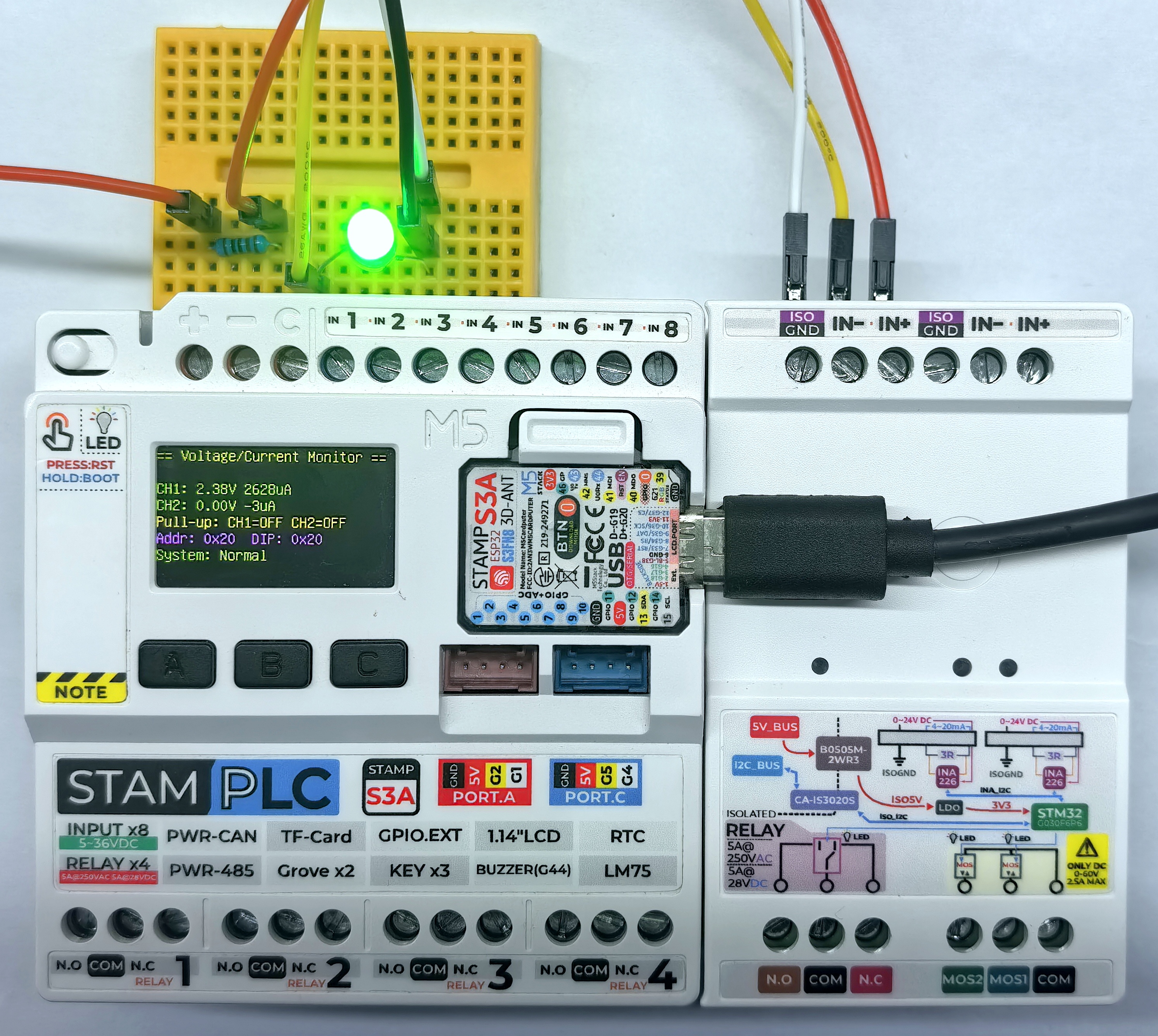
}After power-on, StamPLC IO automatically detects the voltage and current values of the analog signals and displays the detection results on the screen. Press button A to toggle the pull-up resistor state of CH1, and press button B to toggle the pull-up resistor state of CH2. The screen updates the current pull-up resistor state in real time.
PWM Control
#include <M5StamPLC.h>

M5Canvas canvas(&M5StamPLC.Display());
M5StamPLC_IO stamplc_io;

constexpr uint16_t PWM_DUTY_MIN              = 0;
constexpr uint16_t PWM_DUTY_MAX              = 1000;
constexpr uint16_t PWM_DUTY_STEP             = 100;
constexpr uint32_t DUTY_UPDATE_INTERVAL_MS   = 300;

uint8_t pwm_freq          = 50;
uint16_t mos1_duty        = PWM_DUTY_MIN;
uint16_t mos2_duty        = PWM_DUTY_MAX;
int16_t duty_step         = PWM_DUTY_STEP;
uint32_t last_update_time = 0;

void updateDisplay()
{
    canvas.fillScreen(TFT_BLACK);
    canvas.setCursor(0, 0);

    canvas.setTextColor(TFT_GREENYELLOW);
    canvas.println("=== PWM Auto Sweep ===");

    canvas.setTextColor(TFT_CYAN);
    canvas.printf("Mode: PWM  Freq: %dHz\n", pwm_freq);
    canvas.printf("MOS1: %s%d%%  MOS2: %s%d%% /%dms\n", duty_step > 0 ? "+" : "-", PWM_DUTY_STEP / 10,
                  duty_step > 0 ? "-" : "+", PWM_DUTY_STEP / 10, DUTY_UPDATE_INTERVAL_MS);

    canvas.setTextColor(TFT_YELLOW);
    canvas.printf("MOS1: %d.%d%% (%d/1000)\n", mos1_duty / 10, mos1_duty % 10, mos1_duty);
    canvas.printf("MOS2: %d.%d%% (%d/1000)\n", mos2_duty / 10, mos2_duty % 10, mos2_duty);
    canvas.pushSprite(0, 0);
}

void setup()
{
    M5StamPLC.begin();
    canvas.createSprite(M5StamPLC.Display().width(), M5StamPLC.Display().height());
    canvas.setTextScroll(true);
    canvas.fillScreen(TFT_BLACK);
    canvas.setTextSize(1);
    canvas.setFont(&fonts::efontCN_16);
    canvas.println("Try to find M5StamPLC IO module...");
    canvas.pushSprite(0, 0);

    while (!stamplc_io.begin()) {
        canvas.println("Not found, retry in 1s...");
        canvas.pushSprite(0, 0);
        delay(1000);
    }

    canvas.printf("Found: 0x%02X  FW: 0x%02X\n", stamplc_io.getCurrentAddress(), stamplc_io.getFirmwareVersion());
    canvas.pushSprite(0, 0);

    pwm_freq = stamplc_io.getPWMFrequency();
    if (pwm_freq == 0) {
        pwm_freq = 50;
        stamplc_io.setPWMFrequency(pwm_freq);
    }

    stamplc_io.setPWMMode(true);
    stamplc_io.setChannelDuty(1, mos1_duty);
    stamplc_io.setChannelDuty(2, mos2_duty);

    updateDisplay();
}

void loop()
{
    M5StamPLC.update();

    bool needUpdate = stamplc_io.syncAddress();
    uint32_t now    = millis();

    if (now - last_update_time >= DUTY_UPDATE_INTERVAL_MS) {
        last_update_time = now;

        int32_t next_duty = static_cast<int32_t>(mos1_duty) + duty_step;
        if (next_duty >= PWM_DUTY_MAX) {
            next_duty = PWM_DUTY_MAX;
            duty_step = -PWM_DUTY_STEP;
        } else if (next_duty <= PWM_DUTY_MIN) {
            next_duty = PWM_DUTY_MIN;
            duty_step = PWM_DUTY_STEP;
        }

        mos1_duty = static_cast<uint16_t>(next_duty);
        mos2_duty = PWM_DUTY_MAX - mos1_duty;

        stamplc_io.setChannelDuty(1, mos1_duty);
        stamplc_io.setChannelDuty(2, mos2_duty);
        needUpdate = true;
    }

    if (needUpdate) updateDisplay();

    delay(10);
}After power-on, the PWM outputs of MOS1 and MOS2 change their duty cycles sequentially. The sequence is: MOS1 duty cycle increases -> MOS2 duty cycle decreases. The corresponding output state is displayed on the screen, and you can also observe the brightness change of the LEDs connected to MOS1 and MOS2.
Relay Control
#include <M5StamPLC.h>

M5Canvas canvas(&M5StamPLC.Display());
M5StamPLC_IO stamplc_io;

constexpr uint32_t OUTPUT_UPDATE_INTERVAL_MS = 500;
constexpr uint8_t OUTPUT_COUNT               = 3;

const uint8_t output_bits[OUTPUT_COUNT] = {
    M5StamPLC_IO::BIT_RELAY_TRIG,
    M5StamPLC_IO::BIT_EX_CTR_1,
    M5StamPLC_IO::BIT_EX_CTR_2,
};

const char* output_names[OUTPUT_COUNT] = {"Relay", "MOS1", "MOS2"};

bool output_state[OUTPUT_COUNT] = {false, false, false};
uint8_t output_step             = 0;
uint32_t last_update_time       = 0;
uint8_t last_output_index       = 0;
bool last_output_state          = false;
bool last_output_valid          = false;

void updateDisplay()
{
    canvas.fillScreen(TFT_BLACK);
    canvas.setCursor(0, 0);

    canvas.setTextColor(TFT_GREENYELLOW);
    canvas.println("=== Output Auto Sequence ===");

    canvas.setTextColor(TFT_CYAN);
    canvas.printf("Addr: 0x%02X\n", stamplc_io.getCurrentAddress());
    canvas.println("Order: Relay -> MOS1 -> MOS2");
    canvas.printf("Interval: %lums\n", static_cast<unsigned long>(OUTPUT_UPDATE_INTERVAL_MS));

    for (uint8_t i = 0; i < OUTPUT_COUNT; i++) {
        canvas.setTextColor(output_state[i] ? TFT_GREEN : TFT_RED);
        canvas.printf("%s: %s\n", output_names[i], output_state[i] ? "ON" : "OFF");
    }

    if (last_output_valid) {
        canvas.setTextColor(TFT_YELLOW);
        canvas.printf("Last: %s -> %s\n", output_names[last_output_index], last_output_state ? "ON" : "OFF");
    }

    canvas.pushSprite(0, 0);
}

void setOutputState(uint8_t index, bool state)
{
    output_state[index] = state;
    stamplc_io.setRelayState(output_bits[index], state);
    last_output_index  = index;
    last_output_state  = state;
    last_output_valid  = true;
    updateDisplay();
}

void setup()
{
    /* Init M5StamPLC*/
    M5StamPLC.begin();
    canvas.createSprite(M5StamPLC.Display().width(), M5StamPLC.Display().height());
    canvas.setTextScroll(false);
    canvas.fillScreen(TFT_BLACK);
    canvas.setTextSize(1);
    canvas.setFont(&fonts::efontCN_16);
    canvas.println("Try to find M5StamPLC IO");
    canvas.pushSprite(0, 0);

    /* Init M5StamPLC IO */
    while (!stamplc_io.begin()) {
        canvas.println("M5StamPLC_IO not found, retry in 1s...");
        canvas.pushSprite(0, 0);
        delay(1000);
    }

    for (uint8_t i = 0; i < OUTPUT_COUNT; i++) {
        setOutputState(i, false);
    }
}

void loop()
{
    M5StamPLC.update();

    if (stamplc_io.syncAddress()) {
        updateDisplay();
    }

    uint32_t now = millis();
    if (now - last_update_time >= OUTPUT_UPDATE_INTERVAL_MS) {
        last_update_time = now;

        uint8_t output_index = output_step % OUTPUT_COUNT;
        bool state           = output_step < OUTPUT_COUNT;
        setOutputState(output_index, state);
        output_step = (output_step + 1) % (OUTPUT_COUNT * 2);
    }

    delay(10);
}After power-on, the relay output turns on and off sequentially in the order: relay -> MOS1 -> MOS2. The corresponding output state is displayed on the screen, and you can also observe the relay indicator and the state changes of the load connected to the relay.
Relay:
MOS1 and MOS2:
3. Compile & Upload
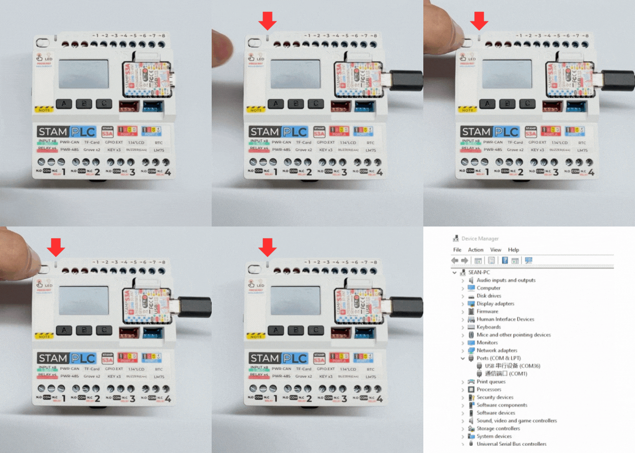
- Long press the Boot button on StamPLC, release it after the red LED lights up. The device will enter download mode and wait for flashing. The red light turns off after the button is released, confirming that the device is in download mode.
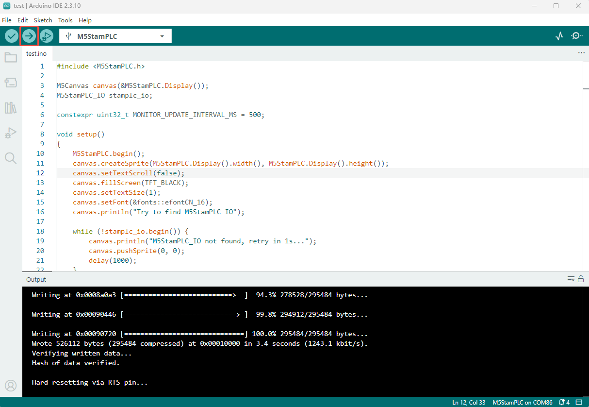
- Select the device port, paste one of the example programs above, click the compile and upload button in the upper left corner of Arduino IDE, and wait for the program to finish compiling and uploading to the device.