Module 4EncoderMotor v1.1
SKU:M138-V11


Description
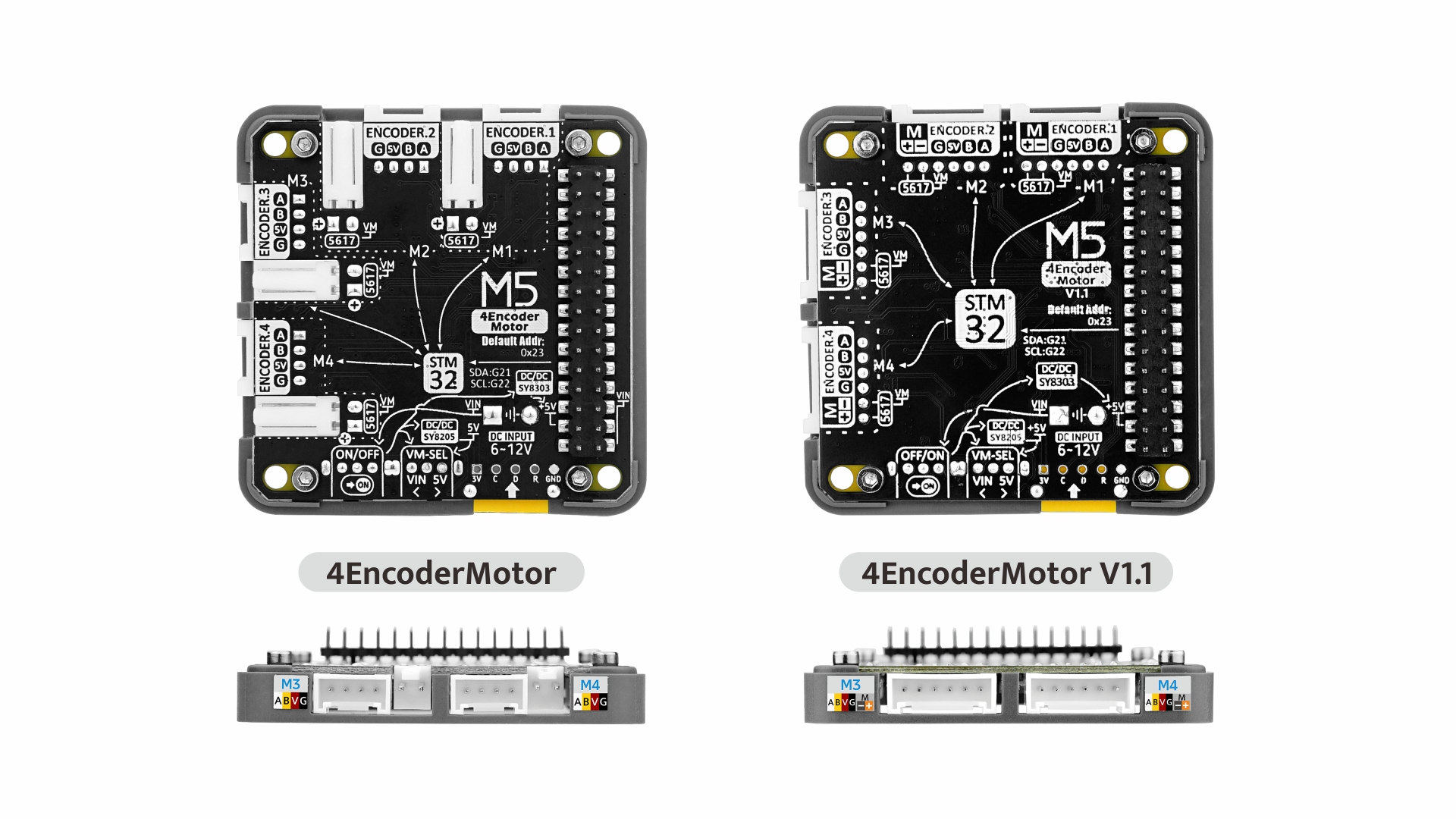
Module 4EncoderMotor v1.1 is a 4-channel encoder motor driver module that uses the STM32 + BL5617 H-bridge driver IC solution. It supports I2C communication, allowing for slave address modification and providing flexible control methods. Through AB pulse encoder signal input, it achieves precise motor motion state and position detection. It supports duty cycle control, absolute position positioning, and speed adjustment modes, enabling various functions such as forward rotation, reverse rotation, stop, and braking of the motor. It integrates INA199 power monitoring to monitor current status in real-time. The onboard power input switch allows for DC 5V or external DC 6 ~ 12V power input. Compared to the previous 4EncoderMotor Module, this product has optimized the interface, adopting a unified HY2.0-6P interface. It is suitable for applications such as robot motion control, automation equipment, smart vehicles, laboratory equipment, and industrial automation systems.
Features
- 4-channel encoder motor driver
- AB pulse signal input
- Duty cycle, absolute position positioning, and speed adjustment control modes
- I2C communication
- Motor voltage input and current monitoring
Includes
- 1 x Module 4EncoderMotor v1.1
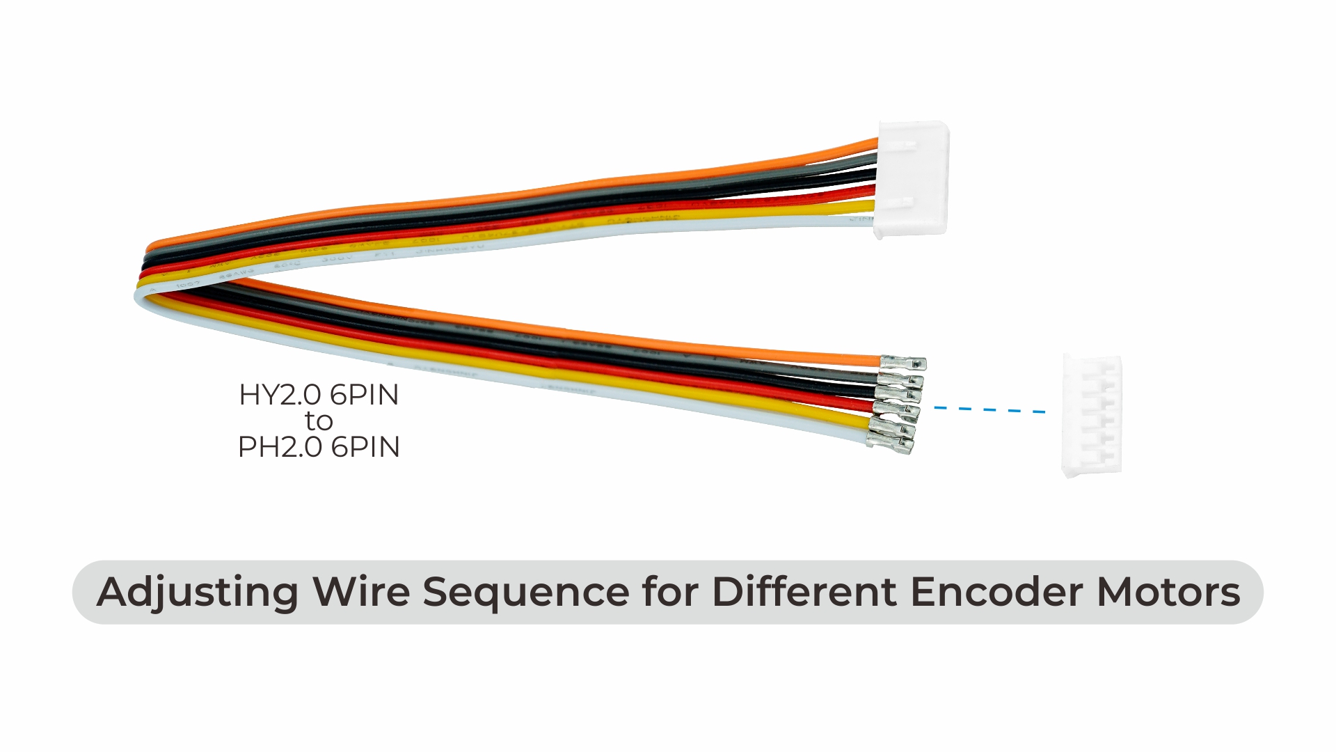
- 4 x HY2.0-6P single-ended cables (20cm)
- 4 x PH2.0-6P connectors
- 1 x DC5521 Female to XT30 Female cable
Applications
- Robot motion control
- Automation equipment
- Industrial automation systems
Specifications
| Specification | Parameter |
|---|---|
| MCU | STM32F030C8T6 |
| Encoder Motor Driver IC | BL5617 |
| Current Detection Chip | INA199 |
| Maximum Supported Current | 3.0A |
| Power | Max 10W |
| External DC Power | 6 ~ 12V |
| Communication Port | I2C @0x24 |
| Standby Current | DC 6V@35.03mA / DC 12V@19.25mA |
| PWM Drive Signal Frequency | 1KHz |
| Operating Temperature | 0°C ~ 40°C |
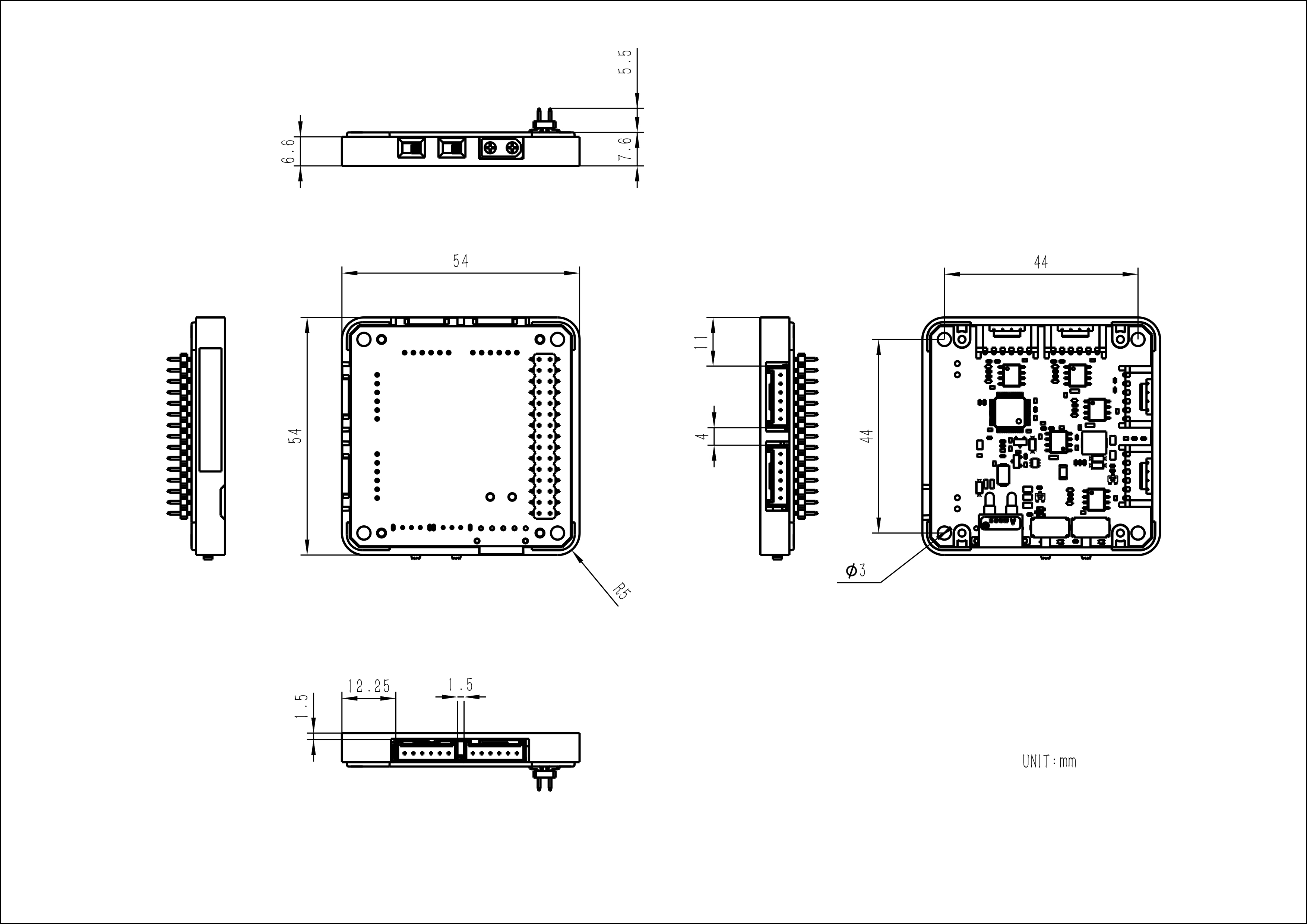
| Product Size | 54.0 x 54.0 x 13.1mm |
| Product Weight | 16.1g |
| Package Size | 95.0 x 66.0 x 26.0mm |
| Gross Weight | 57.8g |
Learn
Encoder Motor Wiring Example
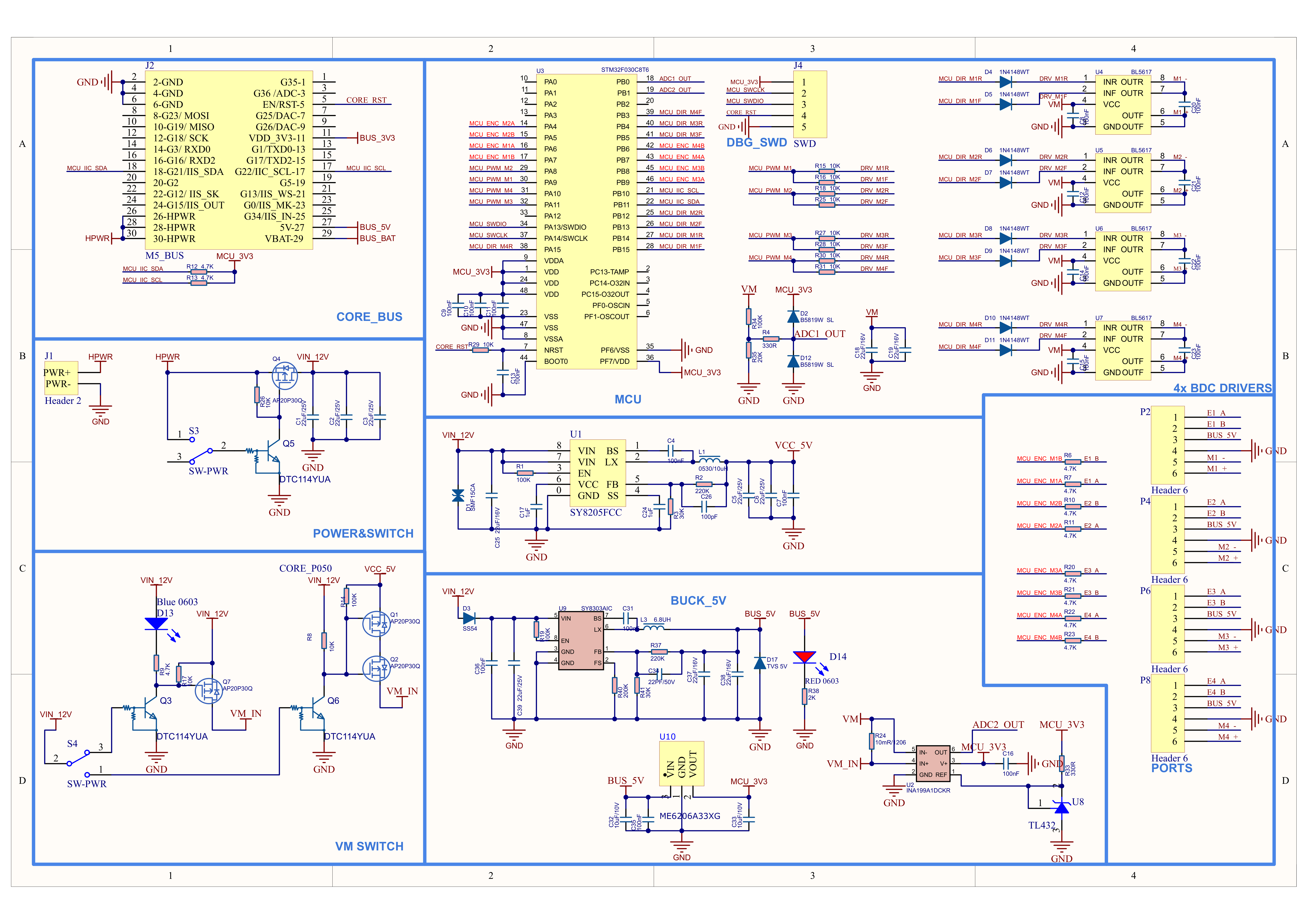
Schematics

PinMap
Current/Voltage Detection Pins
| STM32 | PB0 | PB1 |
|---|---|---|
| Motor Voltage Detect | ADC1_OUT | |
| Current Detect | ADC2_OUT |
Motor Direction Control Pins
| STM32 | PB14/PB15 | PB12/PB13 | PB4/PB5 | PA15/PB3 |
|---|---|---|---|---|
| BL5617 (Direction) | MCU_DIR_M1R/MCU_DIR_M1F | MCU_DIR_M2R/MCU_DIR_M2F | MCU_DIR_M3R/MCU_DIR_M3F | MCU_DIR_M4R/MCU_DIR_M4F |
PWM Control Pins
| STM32 | PA9 | PA8 | PA11 | PA10 |
|---|---|---|---|---|
| BL5617 (PWM) | MCU_PWM_M1 | MCU_PWM_M2 | MCU_PWM_M3 | MCU_PWM_M4 |
A/B Signal Detection Pins
| STM32 | PA6/PA7 | PA4/PA5 | PB9/PB8 | PB7/PB6 |
|---|---|---|---|---|
| Encodering motors | E1_A/E1_B | E2_A/E2_B | E3_A/E3_B | E4_A/E4_B |
M5-Bus
| PIN | LEFT | RIGHT | PIN |
|---|---|---|---|
| GND | 1 | 2 | |
| GND | 3 | 4 | |
| GND | 5 | 6 | RST |
| 7 | 8 | ||
| 9 | 10 | ||
| 11 | 12 | ||
| 13 | 14 | ||
| 15 | 16 | ||
| SDA | 17 | 18 | SCL |
| 19 | 20 | ||
| 21 | 22 | ||
| 23 | 24 | ||
| HPWR | 25 | 26 | |
| HPWR | 27 | 28 | 5V |
| HPWR | 29 | 30 | BAT |
Model Size
Datasheets
Softwares
Arduino
- Module 4EncoderMotor v1.1 Arduino Library
- Module 4EncoderMotor v1.1 Example with Basic
- Module 4EncoderMotor v1.1 Example with Core2
- Module 4EncoderMotor v1.1 Example with CoreS3
Internal Firmware
| Firmware Version | Update | Protocol |
|---|---|---|
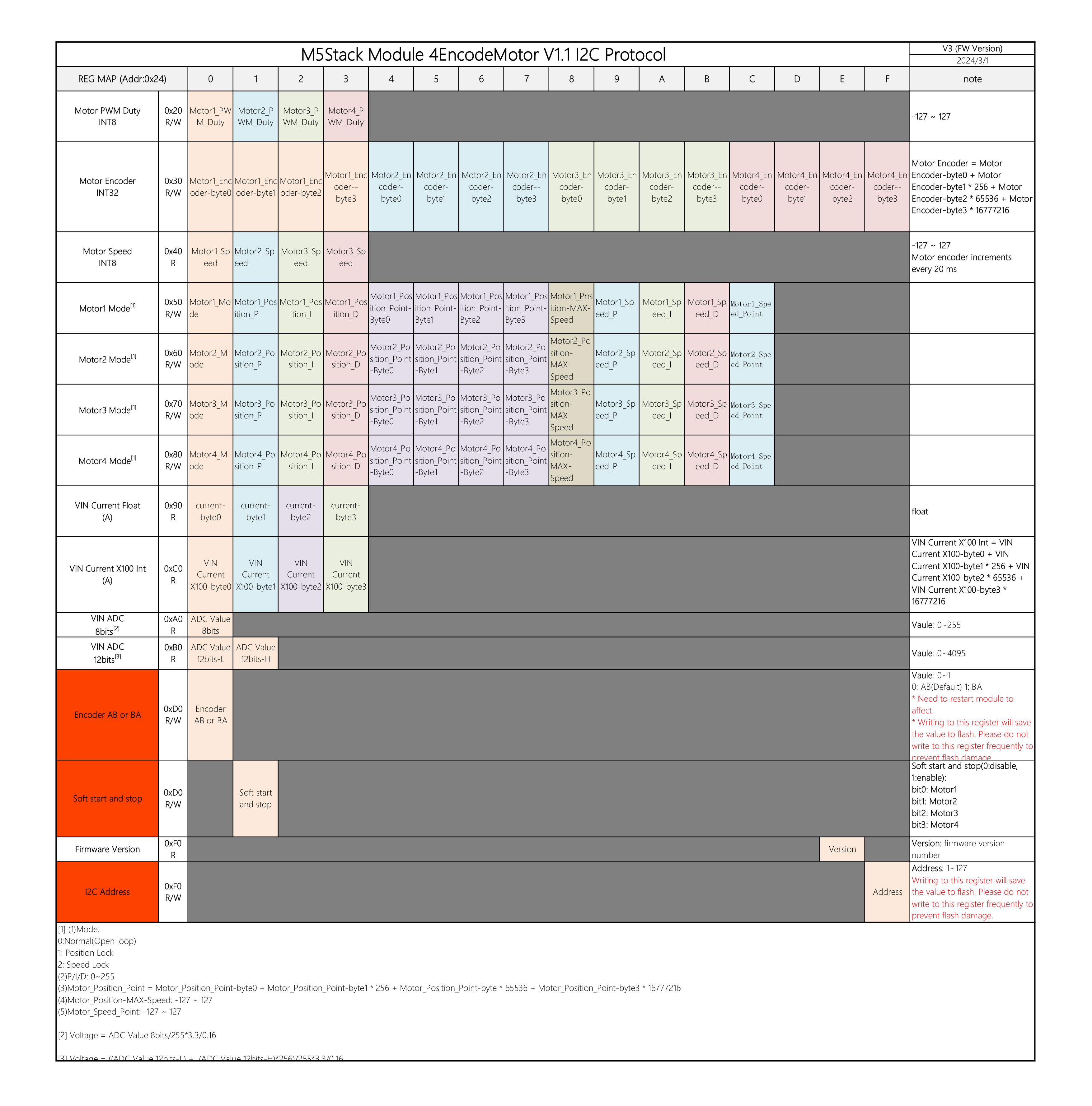
| v3 | First Release Version | Module 4EncoderMotor v1.1 I2C Protocol v3 |
| v4 | 1. Adjust the soft start function and allow setting individual rotation directions for each motor. | Protocol same with v3 |
Protocol
Video
Product Comparison
| Product | Communication Protocol | Chip Solution | Motor Type Supported | Channels | Control Modes | Notes |
|---|---|---|---|---|---|---|
| 4EncoderMotor Module(M138) | I2C(0x24) | STM32+BL5617 | DC Motor/Encoder Motor | 4 | Duty cycle, absolute position, speed control | |
| 4EncoderMotor Module(M138-V11) | I2C(0x24) | STM32+BL5617 | DC Motor/Encoder Motor | 4 | Duty cycle, absolute position, speed control | M138-V11 modified encoder motor interface to HY2.0-6P Grove port |
| DC Motor Module (M021) | I2C(0x56) | MEGA328+L293D | DC Motor/Encoder Motor | 4 | Speed control mode |
