
Module13.2 Servo2
SKU:M014-B
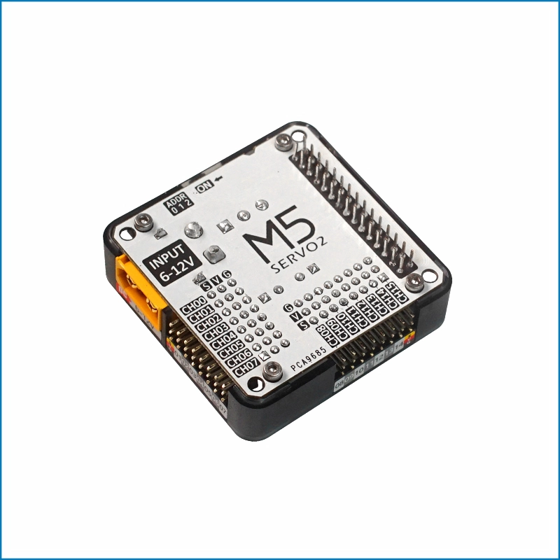
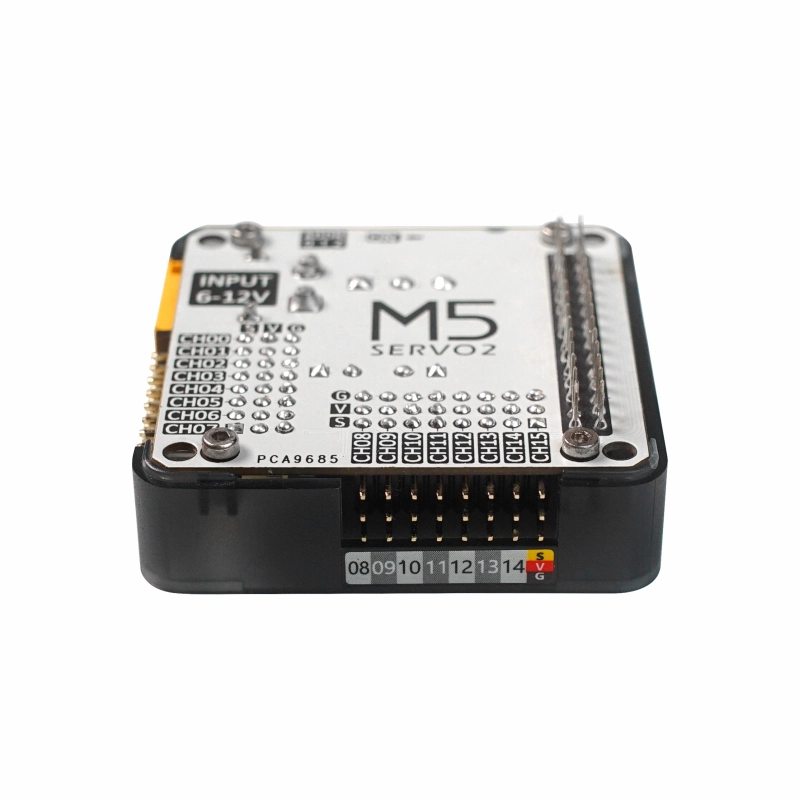
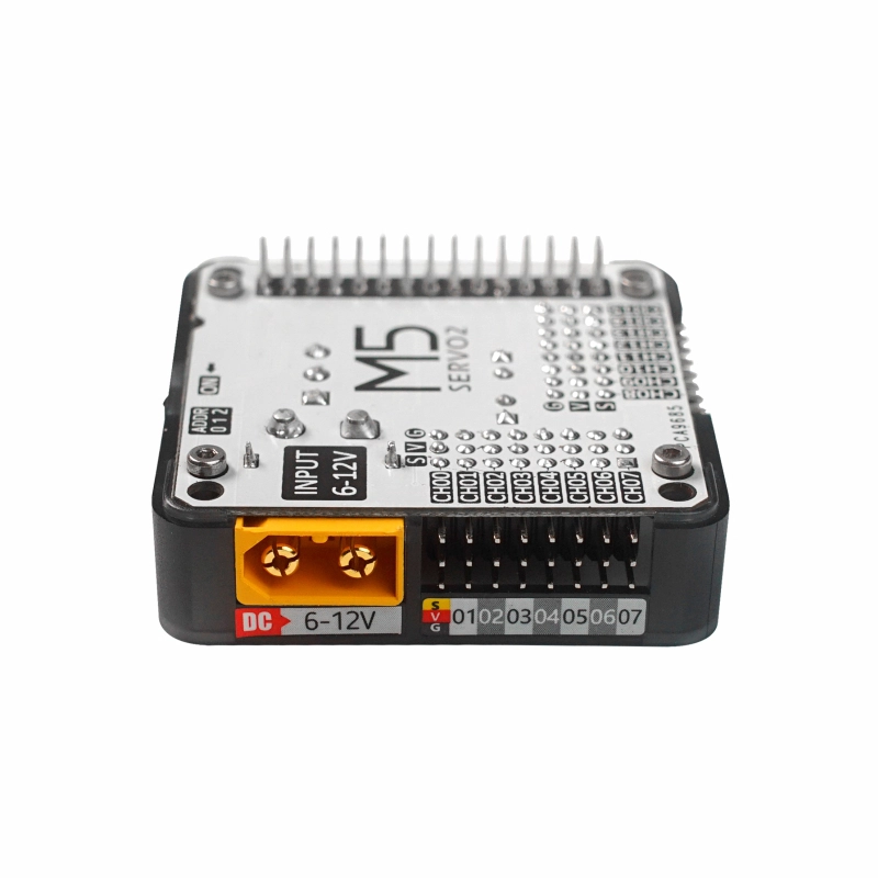
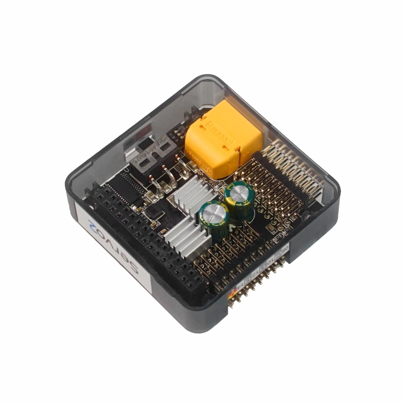
Description
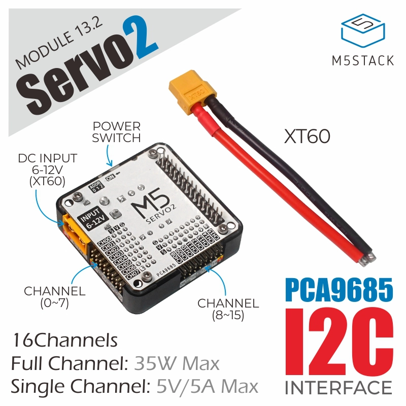
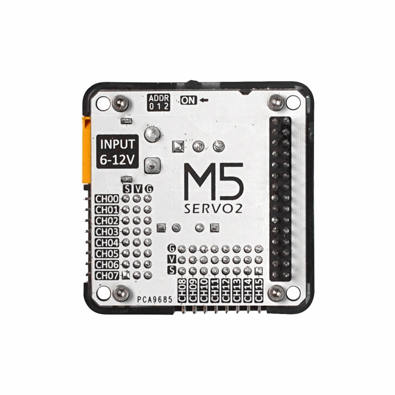
Module13.2 Servo2 is a 16-channel servo driver module designed for M5Stack stackable controllers. It uses a PCA9685 12-bit PWM controller to independently control 16 servo signal channels and communicates with the host through M5-Bus I2C. The onboard 3-bit address DIP switch allows the I2C address to be configured from 0x40 (default) to 0x47, supporting up to eight stacked modules (each module requires an independent power supply).
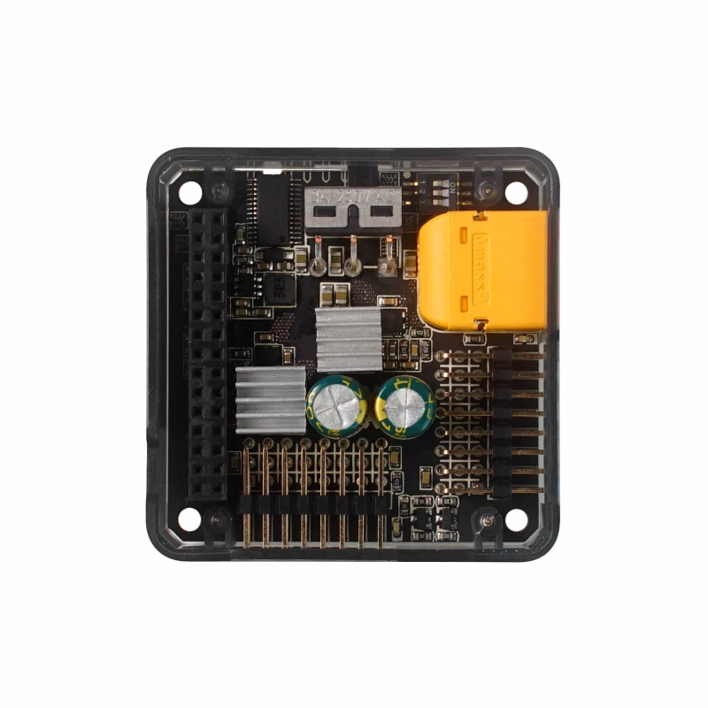
The logic circuitry and servo power supply are independent. The PCA9685 is powered by 3.3V from M5-Bus, while the 16 servo ports are divided into two groups of eight. Two SY8368AQQC step-down converters provide separate 5V power rails, with each converter powering one group of eight servo ports. With a DC 6 ~ 12V input through the XT60 connector, the two groups can simultaneously provide up to 5V/3.5A x 2 (35W total), while a single group can provide up to 5V/5A (25W). When powered by a compatible battery base, the maximum supported output is 5V/2A. The onboard power switch controls power to Module13.2 Servo2, and two green indicators show the status of the two 5V output groups.
Note
cfg.output_power = false).Features
- 16 x Servo Drive Channels
- 2 x Power Indicators
- Adjustable I2C Address
- Independent Power Switch Control
- External DC Power Input: 6-12V
- DC Connector Type: XT60
Includes
- 1 x Module13.2 Servo2
- 1 x XT60 Power Cable (11.5cm)
Applications
- Humanoid Robots
- Biomimetic Multi-Joint Robots
- 3-Axis Servo Gimbals
Specifications
| Specification | Parameter |
|---|---|
| PWM Controller | PCA9685 |
| PWM Resolution | 12-bit (4096 steps) |
| Servo Channels | 16 channels, 2 groups of 8 |
| Communication Interface | I2C @0x40 (default) ~ 0x47 |
| External Power Input | DC 6 ~ 12V |
| External Power Connector | XT60 |
| Servo Output Voltage | 5V |
| Dual-Group Load Capacity | 5V/3.5A per group, 35W maximum total |
| Maximum Single-Group Load | 5V/5A, 25W maximum |
| Battery Base Load Capacity | Up to 5V/2A |
| Power Indicators | 2 x Green LEDs |
| Product Size | 54.2 x 54.2 x 19.7mm |
| Product Weight | 28.0g |
| Package Size | 135.0 x 95.0 x 20.5mm |
| Gross Weight | 60.0g |
Learn
I2C Address Switching
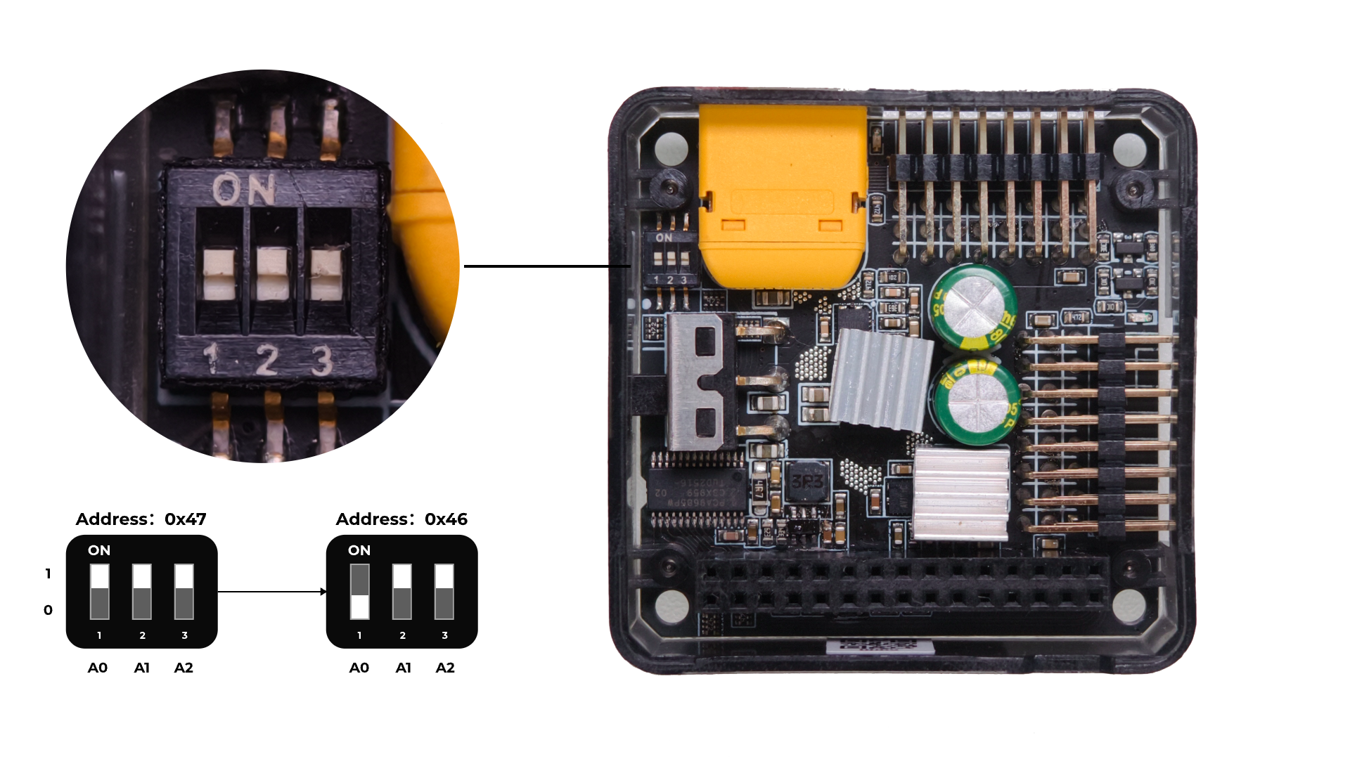
Module13.2 Servo2 has an onboard 3-bit DIP switch for configuring the I2C address. Switches 1, 2, and 3 correspond to address bits A0, A1, and A2, respectively. The UP position represents 1, and the DOWN position represents 0. Configure the DIP switch while the device is powered off, then power-cycle the device for the new address to take effect.
| A0 | A1 | A2 | 7-bit I2C Address |
|---|---|---|---|
| 0 | 0 | 0 | 0x40 |
| 1 | 0 | 0 | 0x41 |
| 0 | 1 | 0 | 0x42 |
| 1 | 1 | 0 | 0x43 |
| 0 | 0 | 1 | 0x44 |
| 1 | 0 | 1 | 0x45 |
| 0 | 1 | 1 | 0x46 |
| 1 | 1 | 1 | 0x47 |
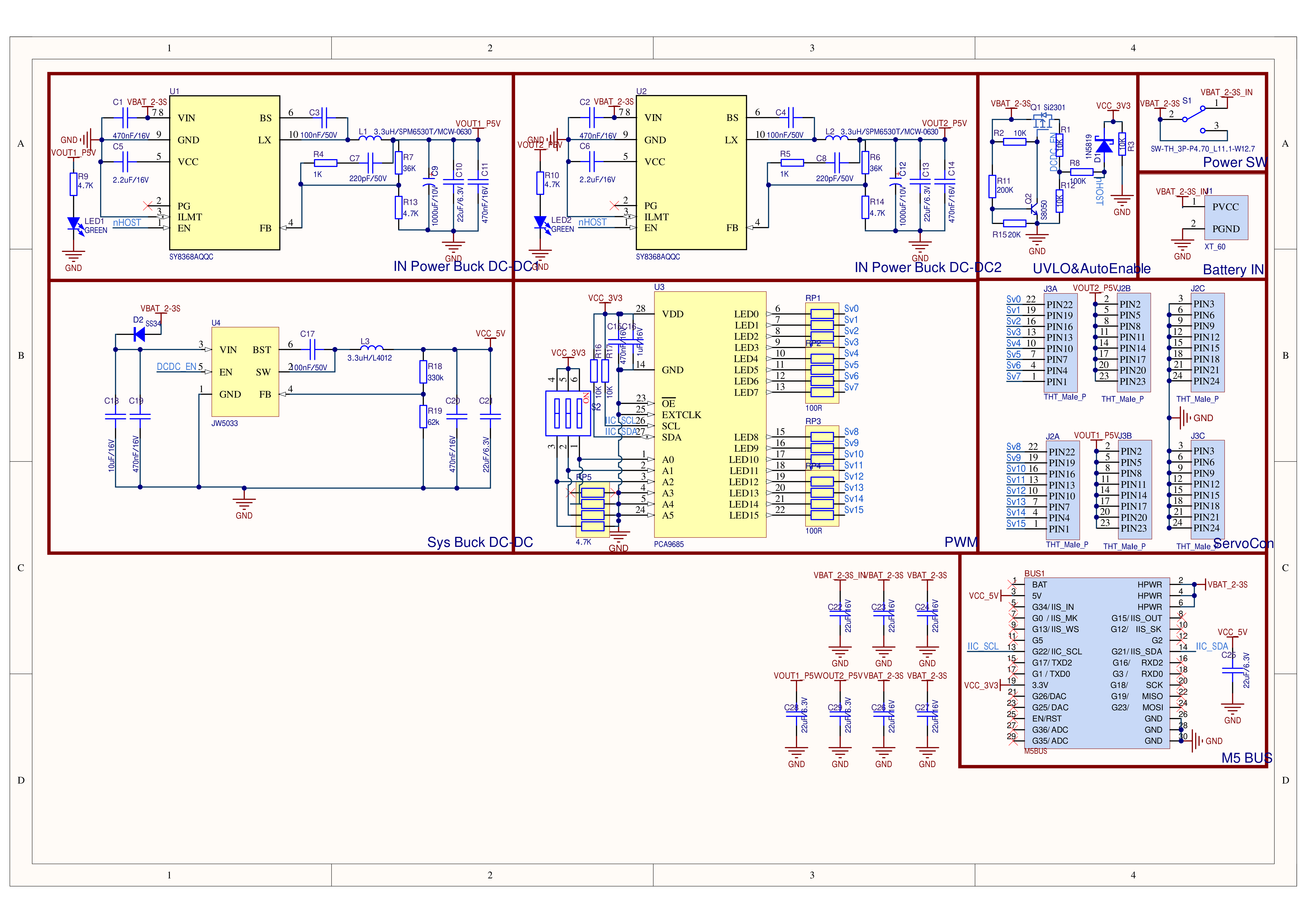
Schematics
PinMap
M5-Bus
| PIN | LEFT | RIGHT | PIN |
|---|---|---|---|
| GND | 1 | 2 | |
| GND | 3 | 4 | |
| GND | 5 | 6 | |
| 7 | 8 | ||
| 9 | 10 | ||
| 11 | 12 | 3V3 | |
| 13 | 14 | ||
| 15 | 16 | ||
| SDA | 17 | 18 | SCL |
| 19 | 20 | ||
| 21 | 22 | ||
| 23 | 24 | ||
| HPWR | 25 | 26 | |
| HPWR | 27 | 28 | 5V |
| HPWR | 29 | 30 |
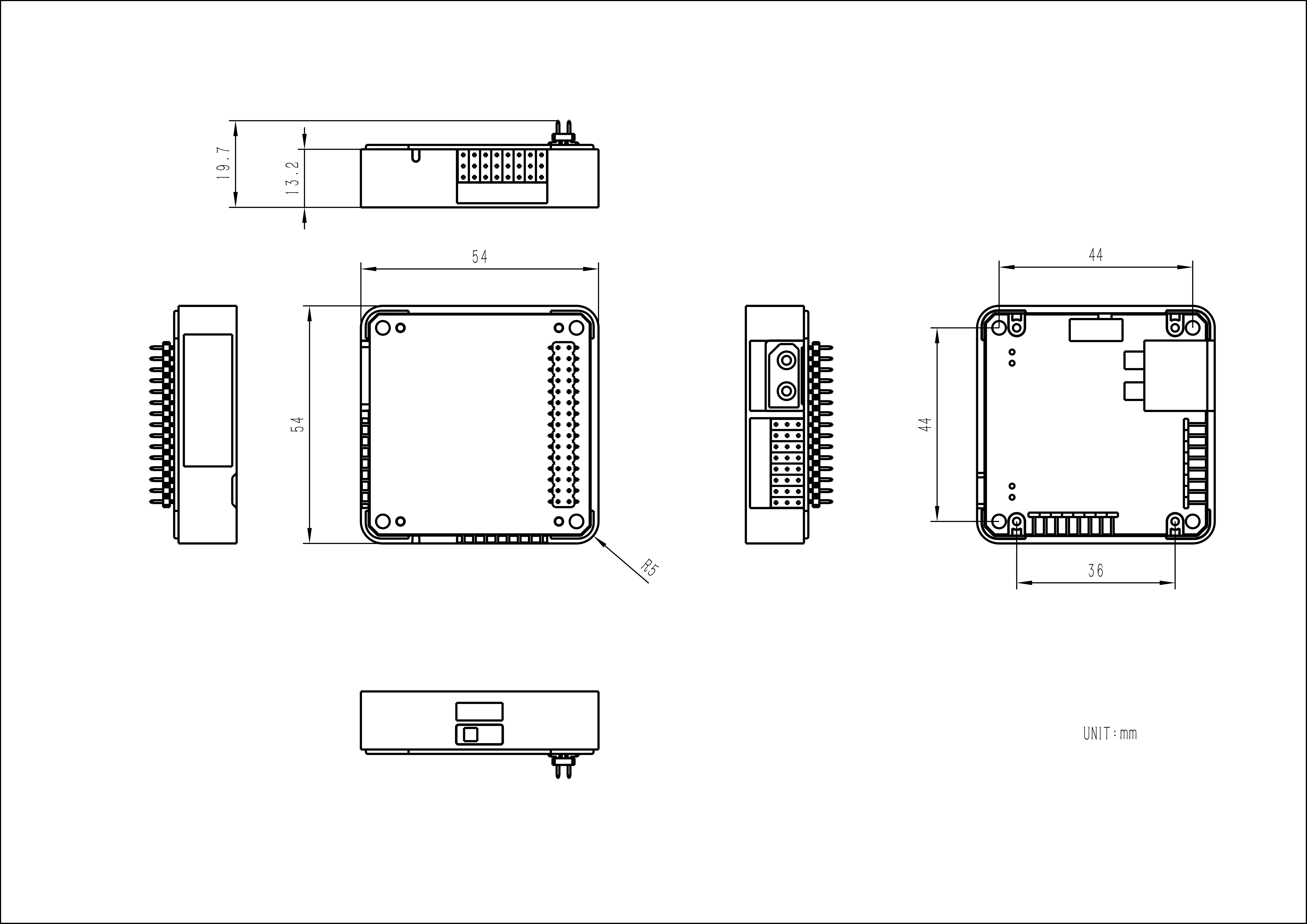
Model Size
Datasheets
Softwares
0x70 enabled by default for synchronizing multiple chips. After power-on, the module responds not only to requests sent to its own I2C communication address (0x40 ~ 0x47), but also to the ALL_CALL I2C address 0x70. If a device with the same address is connected to the current I2C bus, an address conflict will occur and communication may fail. This can be resolved by configuring the ALLCALL bit (bit:0) in the PCA9685 MODE1 register (0x00H) to 0 to disable the ALL_CALL function. See the Module13.2 Servo2 ALL_CALL Configuration example program.