CoreS3
SKU:K128
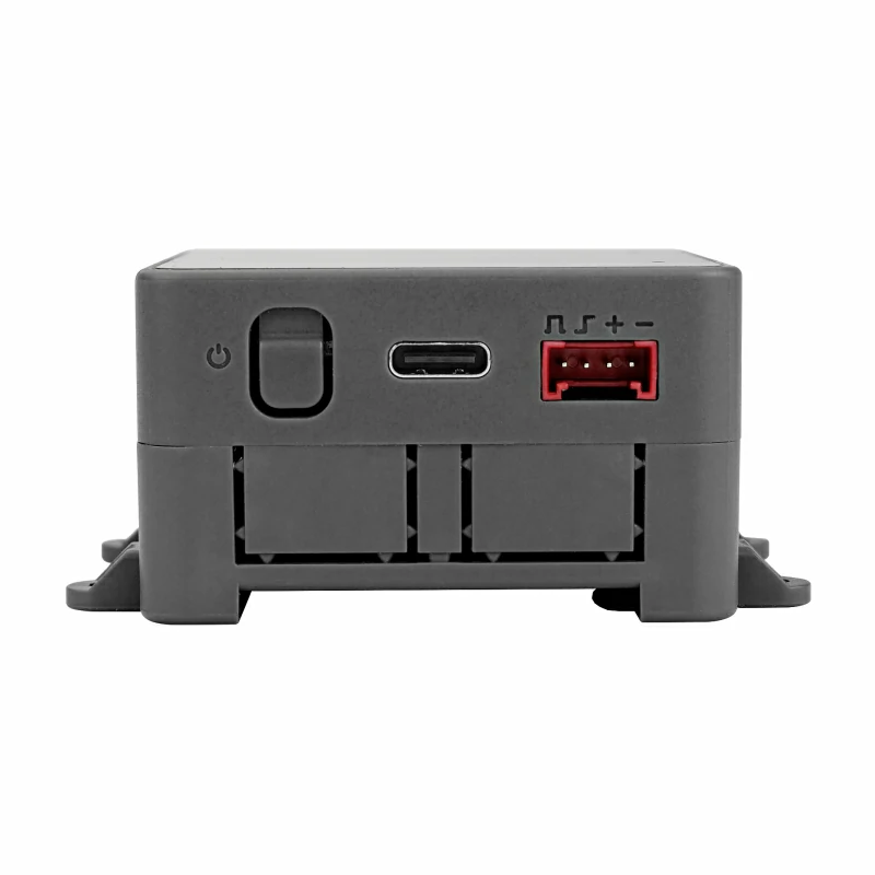


Description
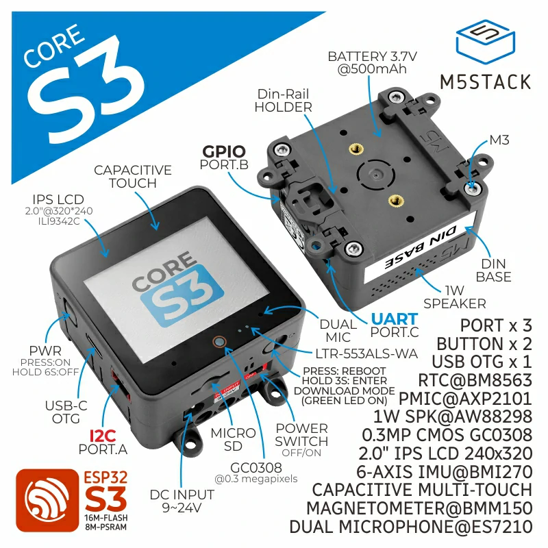
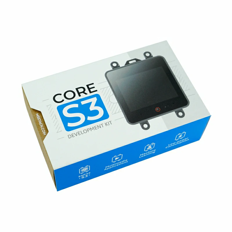
CoreS3 is the third generation of the M5Stack Core series. Powered by the ESP32-S3 solution, this kit features a dual-core Xtensa LX7 processor running at 240MHz. CoreS3 comes equipped with built-in Wi-Fi functionality, enabling seamless connectivity. It boasts 16MB of onboard flash memory and 8MB of PSRAM, providing ample space for program storage.
CoreS3 offers convenient programming options through its TYPE-C interface, supporting OTG and CDC functions. This allows for easy connection with external USB devices and hassle-free firmware flashing. CoreS3 features a 2.0-inch capacitive touch IPS screen, protected by high-strength glass material. Additionally, a 30W pixel camera GC0308 is integrated at the bottom of the screen, accompanied by a proximity sensor LTR-553ALS-WA for enhanced functionality. Power management is handled by the AXP2101 power management core chip, employing a 4-way power flow control loop for efficient power distribution. The overall design emphasizes low power consumption. CoreS3 also features a 6-axis attitude sensor BMI270 and a magnetometer BMM150 for precise motion detection. With the onboard TF-card (microSD) card slot and BM8563 RTC chip, accurate timing and sleep-timer wake-up functions are readily available.
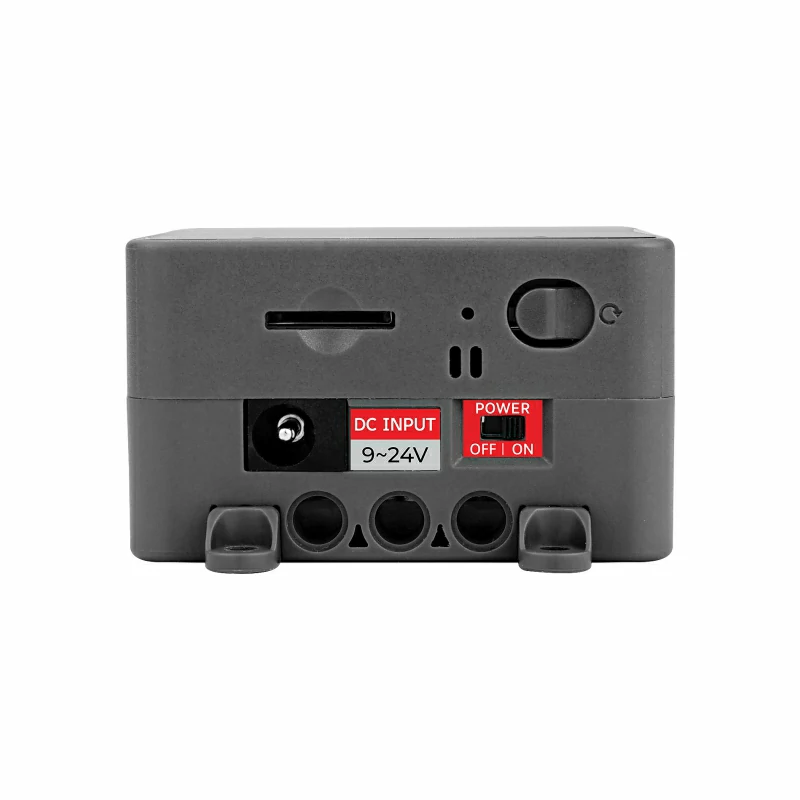
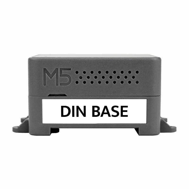
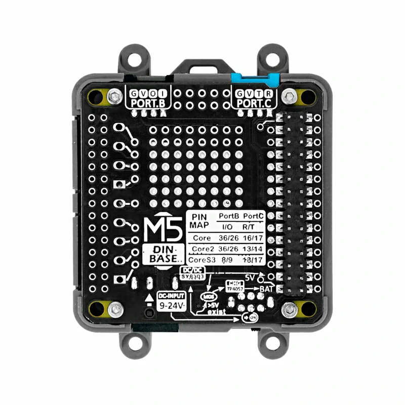
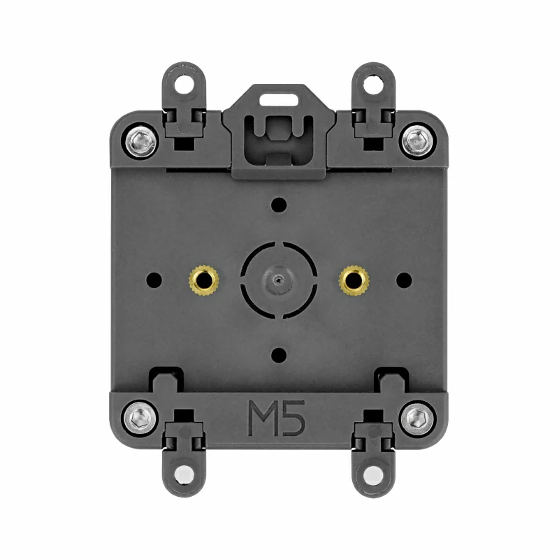
Sound output on CoreS3 is optimized with the high-fidelity 16-bit I2S power amplifier chip AW88298, accompanied by a built-in 1W speaker for clear audio playback. For sound input, the kit incorporates the ES7210 audio decoding chip and dual-microphone input. The side of the device includes an independent power button and restart (RST) button, complemented by a self-built delay circuit. By long-pressing the reset button, users can easily enter the program download mode. The CoreS3 kit comes with the DinBase Base, providing convenient options for Din rail, wall, and screw fixing. It can be powered by an external DC 12V (supports 9~24V) or an internal 500mAh lithium battery. The DinBase also offers multiple proto locations for users to customize and expand their projects. CoreS3 is an ideal choice for IoT development, various DIY project development, smart home control systems, and industrial automation control systems.
Tutorials & Quick Start
Features
- Developed based on ESP32, support WiFi @16M Flash, 8M PSRAM
- Built-in camera, proximity sensor, speaker, power indicator, RTC, I2S amplifier, dual microphone, condenser touch screen, power button, reset button, gyroscope
- TF card slot
- High-strength glass
- Support OTG and CDC functions
- AXP2101 power management, low power design
- Supported programming platforms: Arduino, UIFlow
Includes
- 1 × CoreS3
- 1 × DinBase
- 1 × M3 Hex Wrench
- 1 × Hanger(large)
- 4 × Hanger(small)
Applications
- IoT development
- Various DIY project development
- Smart home control system
- Industrial automation control system
Specifications
| Resources | Parameters |
|---|---|
| SoC | ESP32-S3@Xtensa LX7, 16MFLASH AND 8M-PSRAM, WIFI, OTG\CDC functions |
| Touch the IPS LCD screen | 2.0"@320*240 ILI9342C |
| Camera | GC0308@300000 pixels |
| Proximity sensors | LTR-553ALS-WA |
| Power management chip | AXP2101 |
| Six-axis attitude sensor | BMI270 |
| Three-axismagnetometer | BMM150 |
| RTC | BM8563 |
| Speaker | 16bits-I2S power amplifier chip AW88298@1W |
| Audio decoding chip | ES7210, dual microphone inputs |
| Product Size | 54 x 54 x 16mm |
| Product Size | Full Assembly Kit(CoreS3+DinBase):54 * 54 * 31.5mm CoreS3:54 * 54 * 15.5mm |
| Package Size | 101*64*34mm |
| Product Weight | 73.3g |
| Package Weight | 97.8g |
Learn
.gif)
Power On: Press the left power button once.
Power Off: Press and hold the left power button for 6 seconds.
Reset: Press the RST button on the bottom side once.
Download Mode: Press and hold the reset button for 3 seconds (green light on).
Certification Information
- CE/MIC/FCC/SAR
Schematics
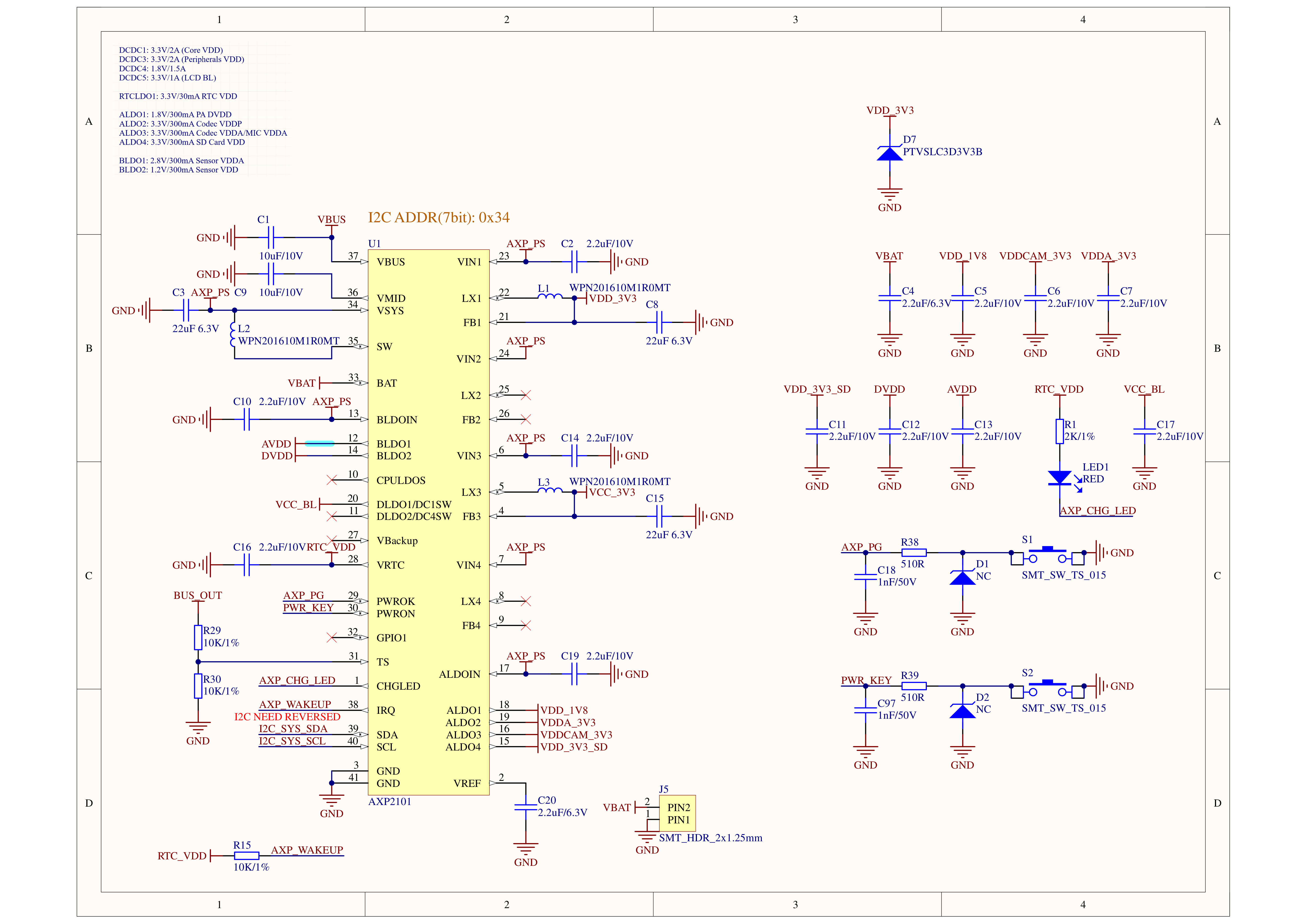
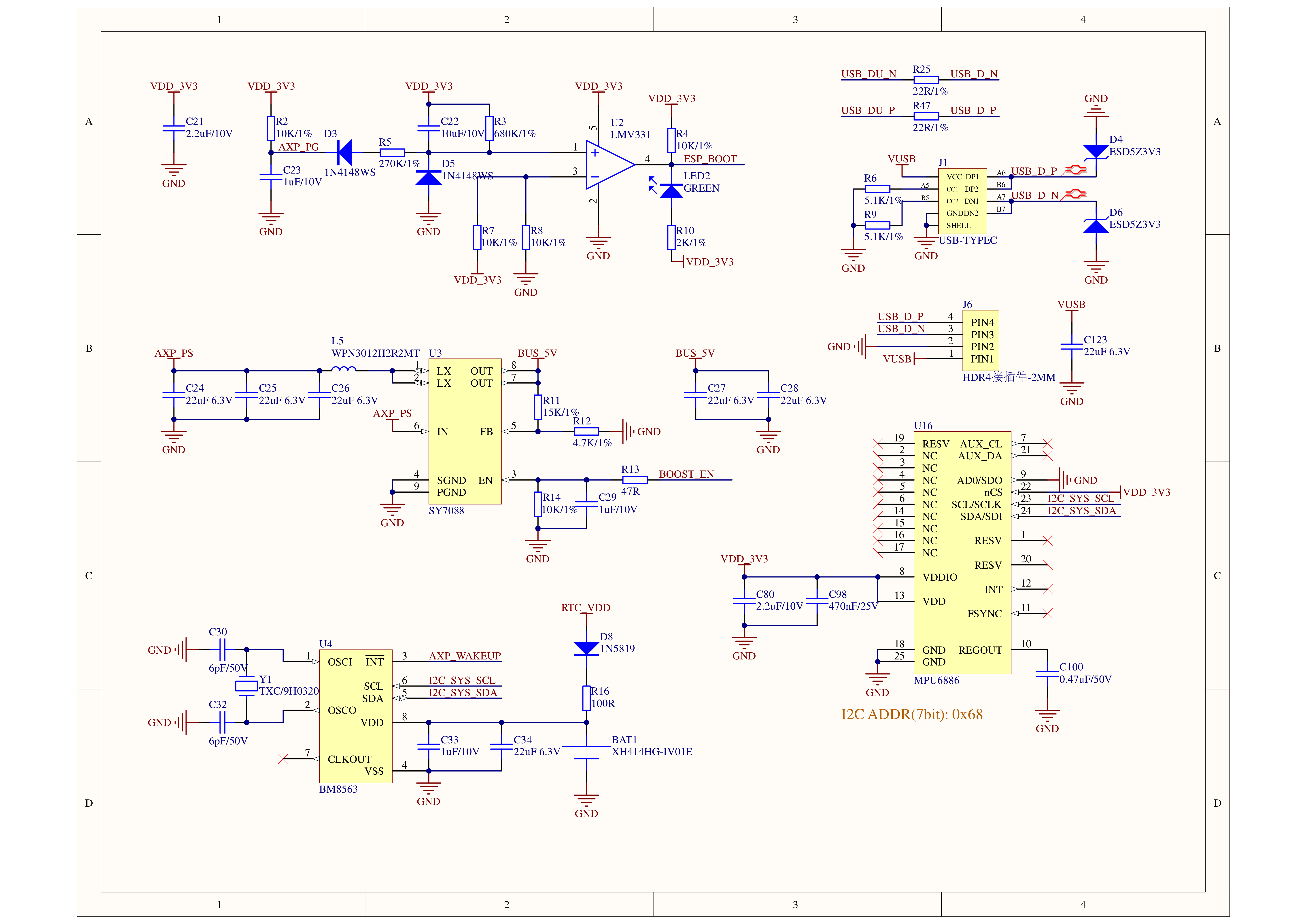
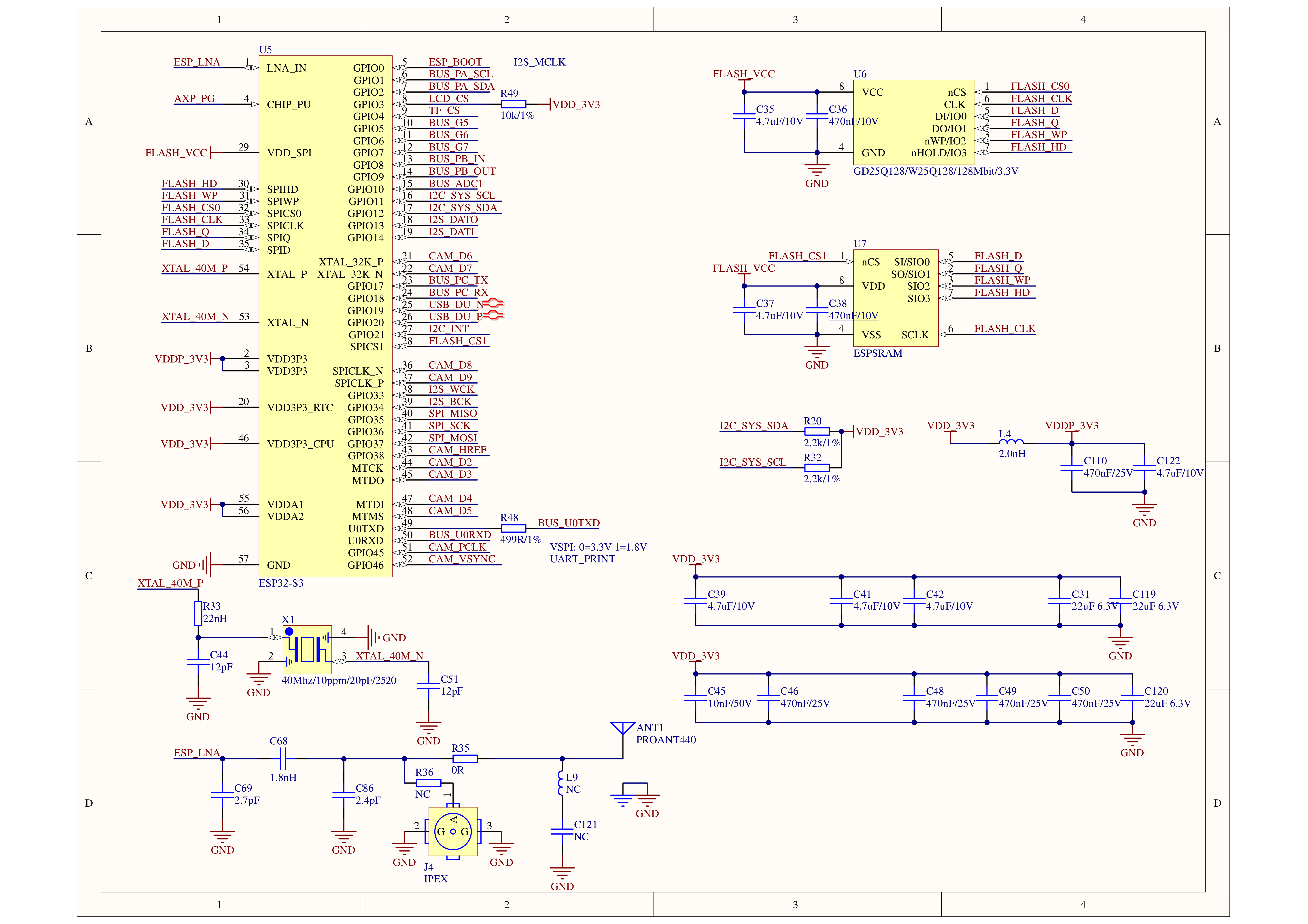
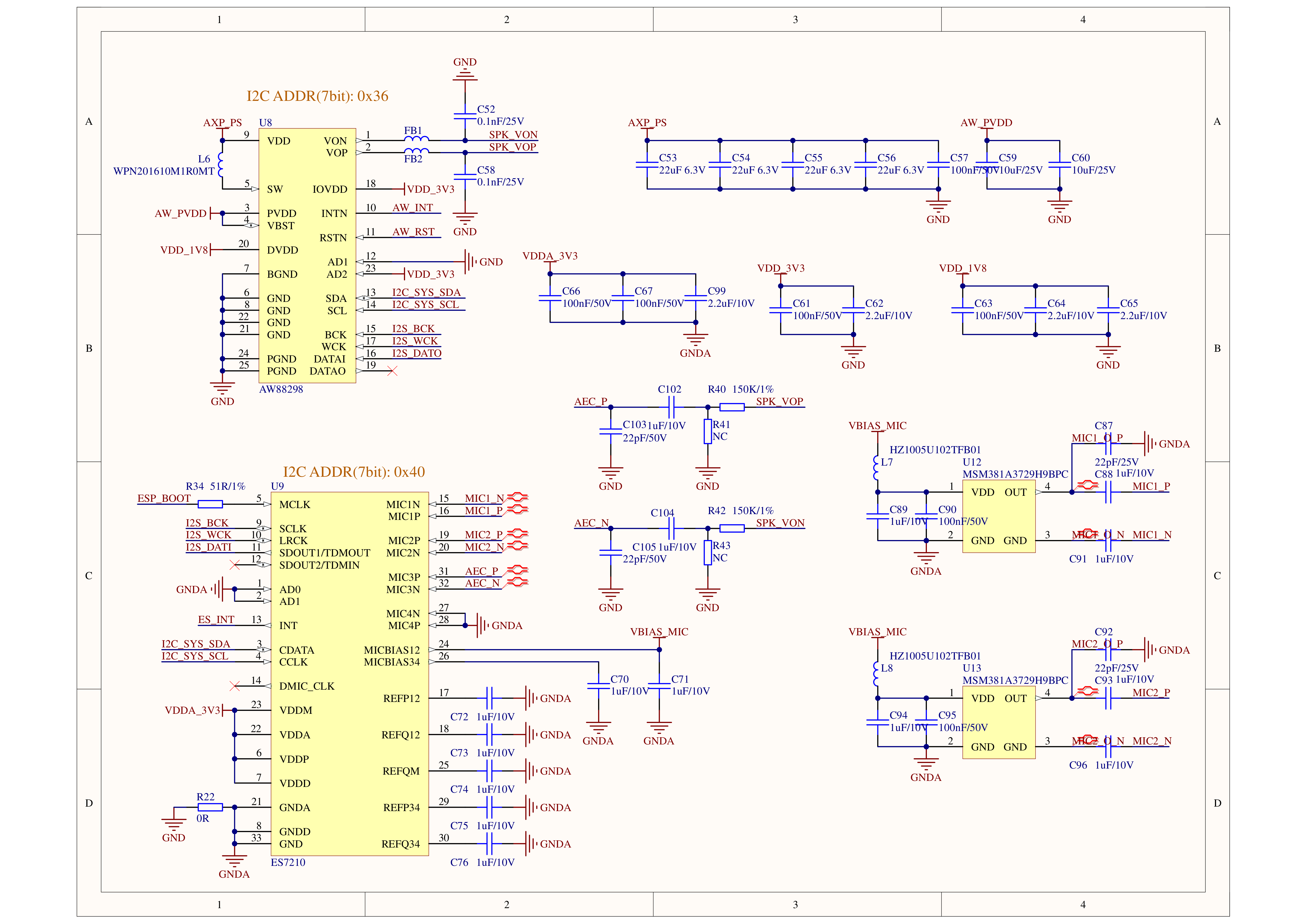
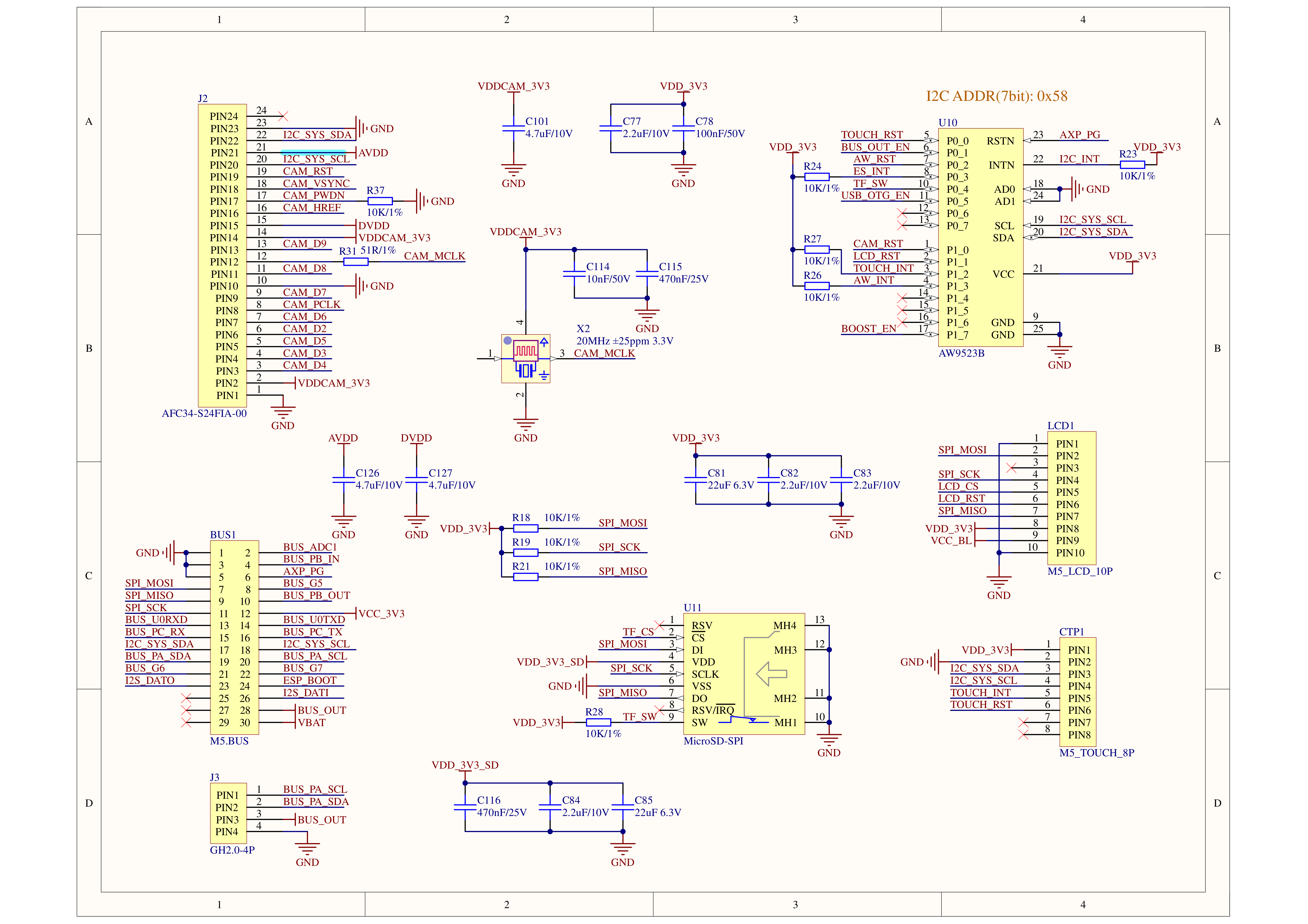
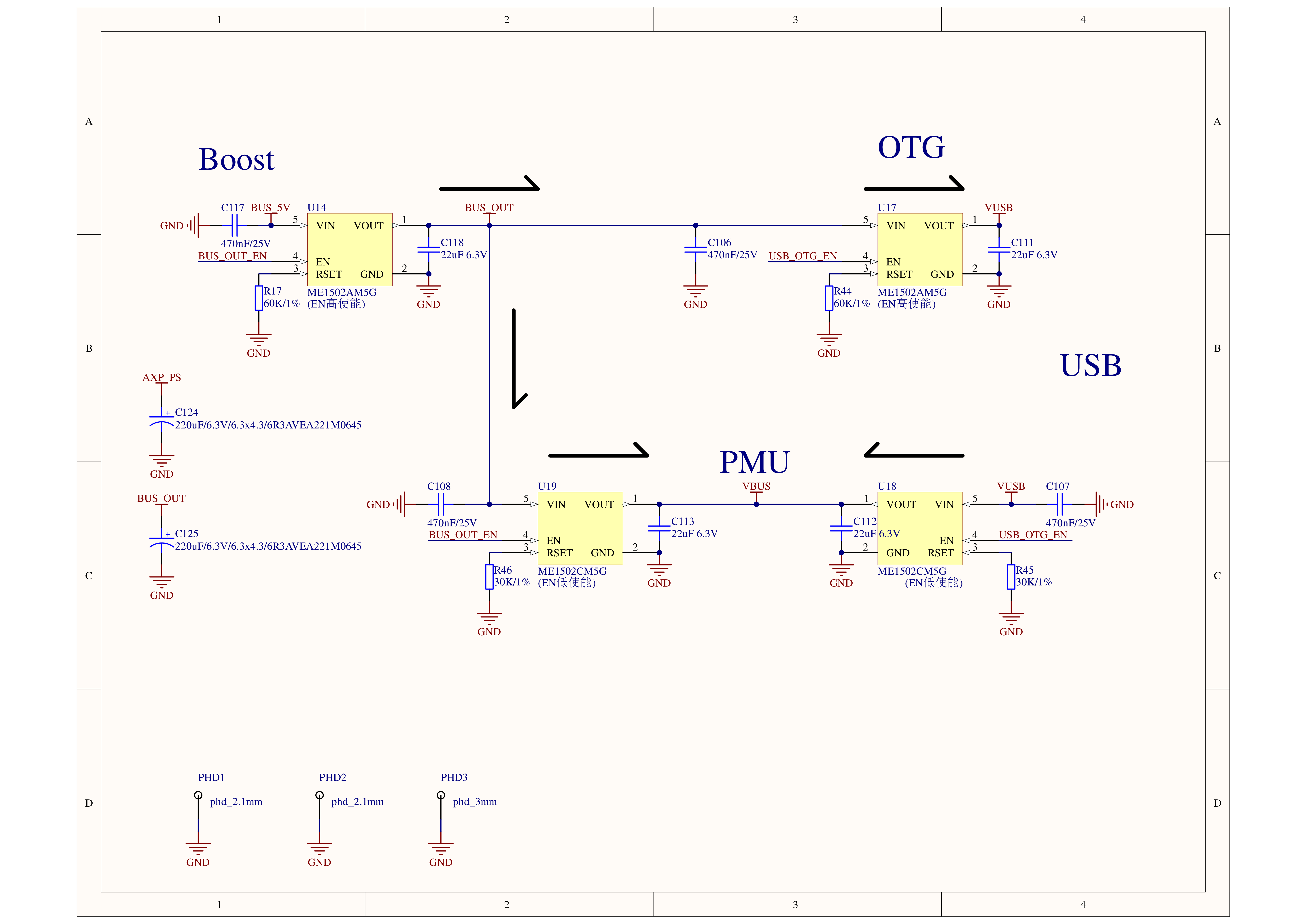
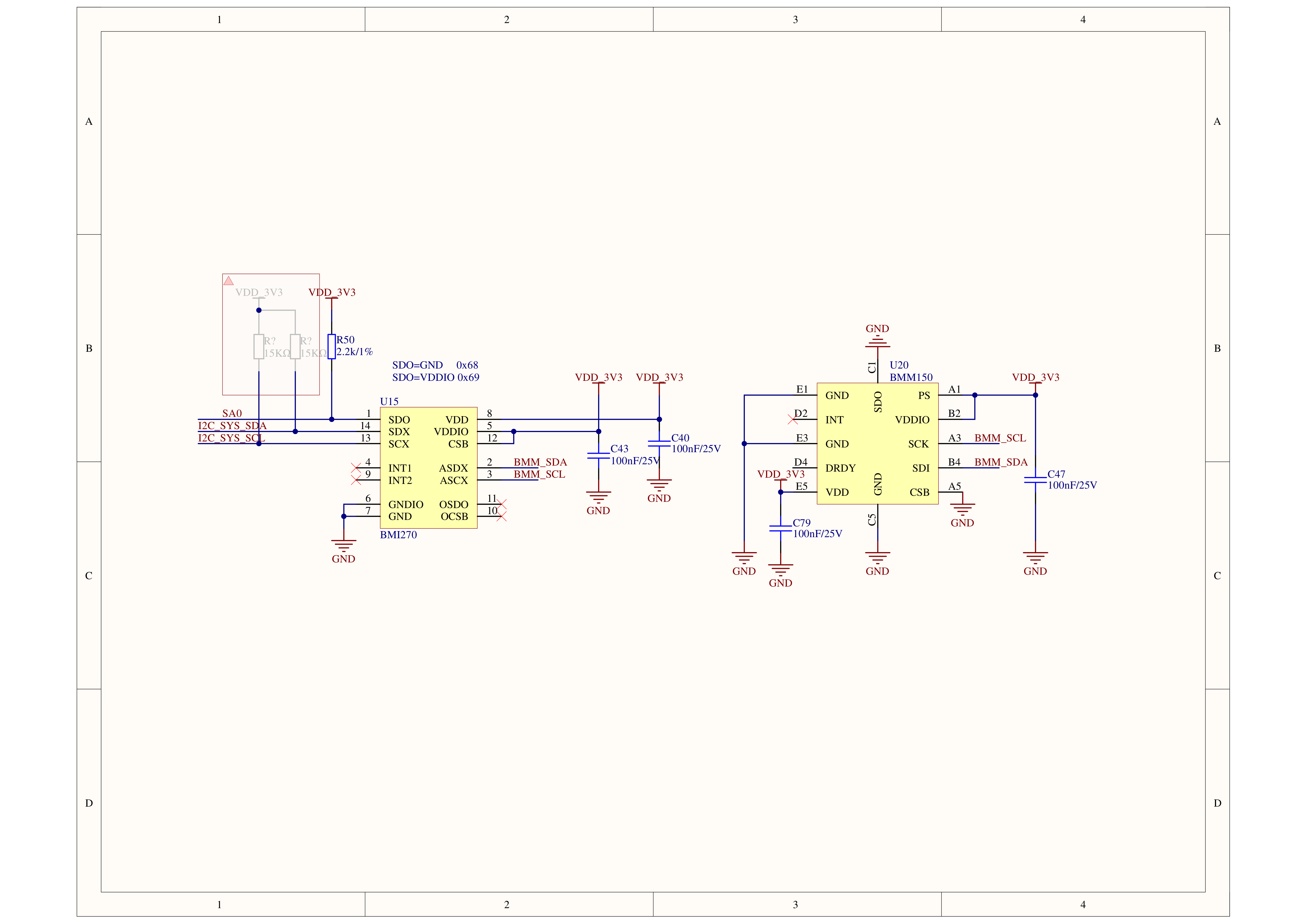


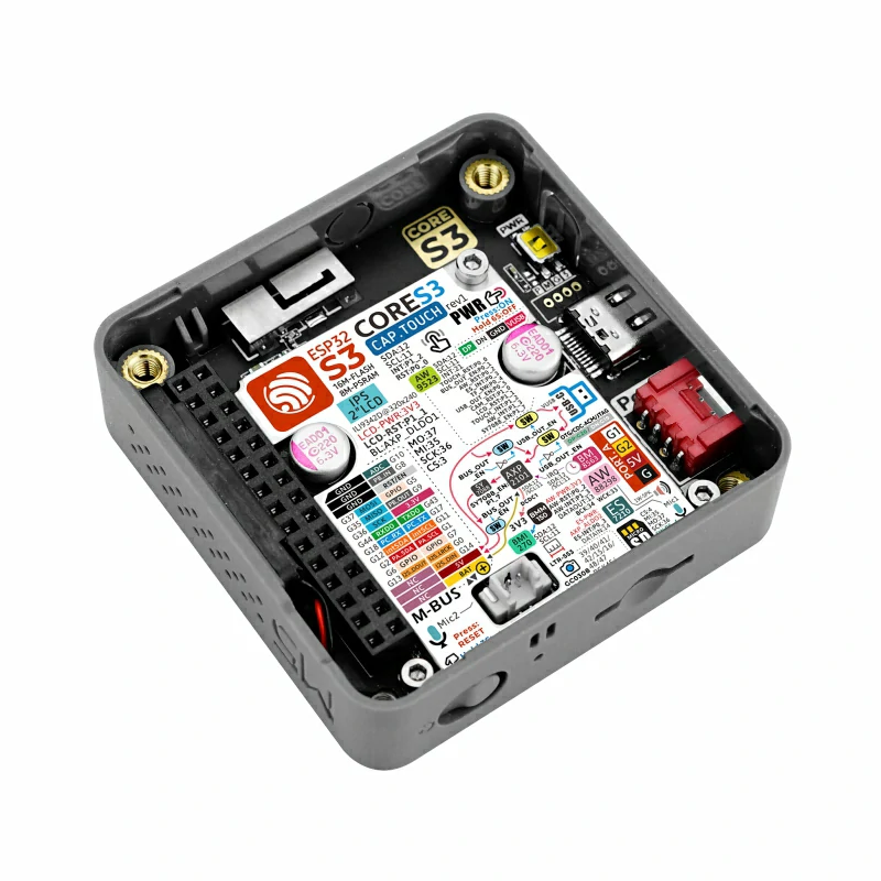
PinMap
LCD Screen & TF Card
LCD Pixel:320x240 TF cards support up to 16GB
| ESP32S3 Chip | GPIO37 | GPIO36 | GPIO3 | GPIO35 | GPIO4 | |||
|---|---|---|---|---|---|---|---|---|
| AW9523B | AW9523B_P1_1 | |||||||
| AXP2101 | AXP2101_DLDO1 | AXP2101_LX1 | ||||||
| ILI9342C | MOSI | SCK | CS | DC | RST | BL | PWR | |
| TF Card | SPI_MOSI | SPI_SCK | SPI_MISO | TF_CS |
Camera & Proximity sensors LTR-553ALS-WA
| ESP32S3 Chip | GPIO12 | GPIO11 | AW9523B_P1_0 | GPIO45 | GPIO46 | GPIO38 |
|---|---|---|---|---|---|---|
| GC0308 | I2C_SYS_SDA | I2C_SYS_SCL | CAM_RST | CAM_PCLK | CAM_VSYNC | CAM_HREF |
| LTR-553ALS-WA | I2C_SYS_SDA | I2C_SYS_SCL |
The LTR-553ALS-WA proximity sensor and camera are integrated in a single line, using I2C for communication, and the detailed communication address is shown in the table above.
CAP.TOUCH (I2C Addr: 0x38)
| ESP32S3 chip | GPIO12 | GPIO11 | AW9523B_P1_2 | AW9523B_P0_0 |
|---|---|---|---|---|
| FT6336U | I2C_SYS_SDA | I2C_SYS_SCL | TOUCH_INT | TOUCH_RST |
Microphone & amplifier
| ESP32S3 Chip | GPIO12 | GPIO11 | GPIO34 | GPIO33 | GPIO13 | GPIO14 | GPIO0 | AW9523B_P1_3 | AW9523B_P0_2 |
|---|---|---|---|---|---|---|---|---|---|
| ES7210(0x40) | I2C_SYS_SDA | I2C_SYS_SCL | I2S_BCK | I2S_WCK | I2S_DATO | I2S_MCLK | |||
| AW88298(0x36) | I2C_SYS_SDA | I2C_SYS_SCL | I2S_BCK | I2S_WCK | I2S_DAT1 | AW_INT | AW_RST |
AXP Power Led
| AXP2101 | AXP_CHG_LED |
|---|---|
| Red LED | RTC_VDD |
RTC
| ESP32S3 Chip | GPIO12 | GPIO11 | AXP2101_IRQ |
|---|---|---|---|
| BM8563 | I2C_SYS_SDA | I2C_SYS_SCL | AXP_WAKEUP |
IMU (6-axis gyroscope + 3-axis accelerometer)
| ESP32S3 Chip | GPIO12 | GPIO11 |
|---|---|---|
| BMI270&BMM150 | I2C_SYS_SDA | I2C_SYS_SCL |
Internal I2C connection
| ESP32S3 Chip | GPIO12 | GPIO11 |
|---|---|---|
| BMI270&BMM150 | I2C_SYS_SDA | I2C_SYS_SCL |
| AXP2101 | I2C_SYS_SDA | I2C_SYS_SCL |
| BM8563 | I2C_SYS_SDA | I2C_SYS_SCL |
| ES7210 | I2C_SYS_SDA | I2C_SYS_SCL |
| AW88298 | I2C_SYS_SDA | I2C_SYS_SCL |
PORT
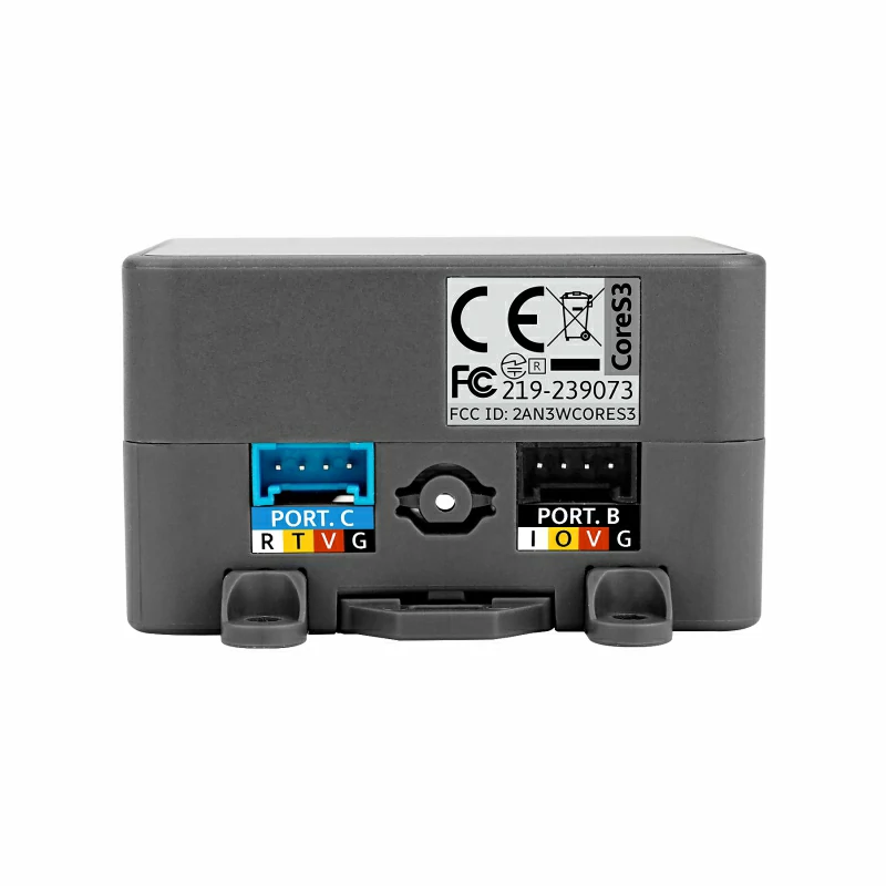
| Port | Pin | NOTE |
|---|---|---|
| PORT-A(RED) | G2/G1 | I2C |
| PORT-B(BLACK) | G9/G8 | GPIO |
| PORT-C(BLUE) | G18/G17 | UART(RX/TX) |
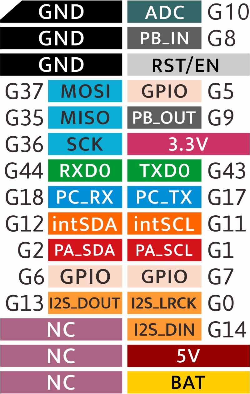
M5CoreS3 M-BUS Schematic diagram

Model Size
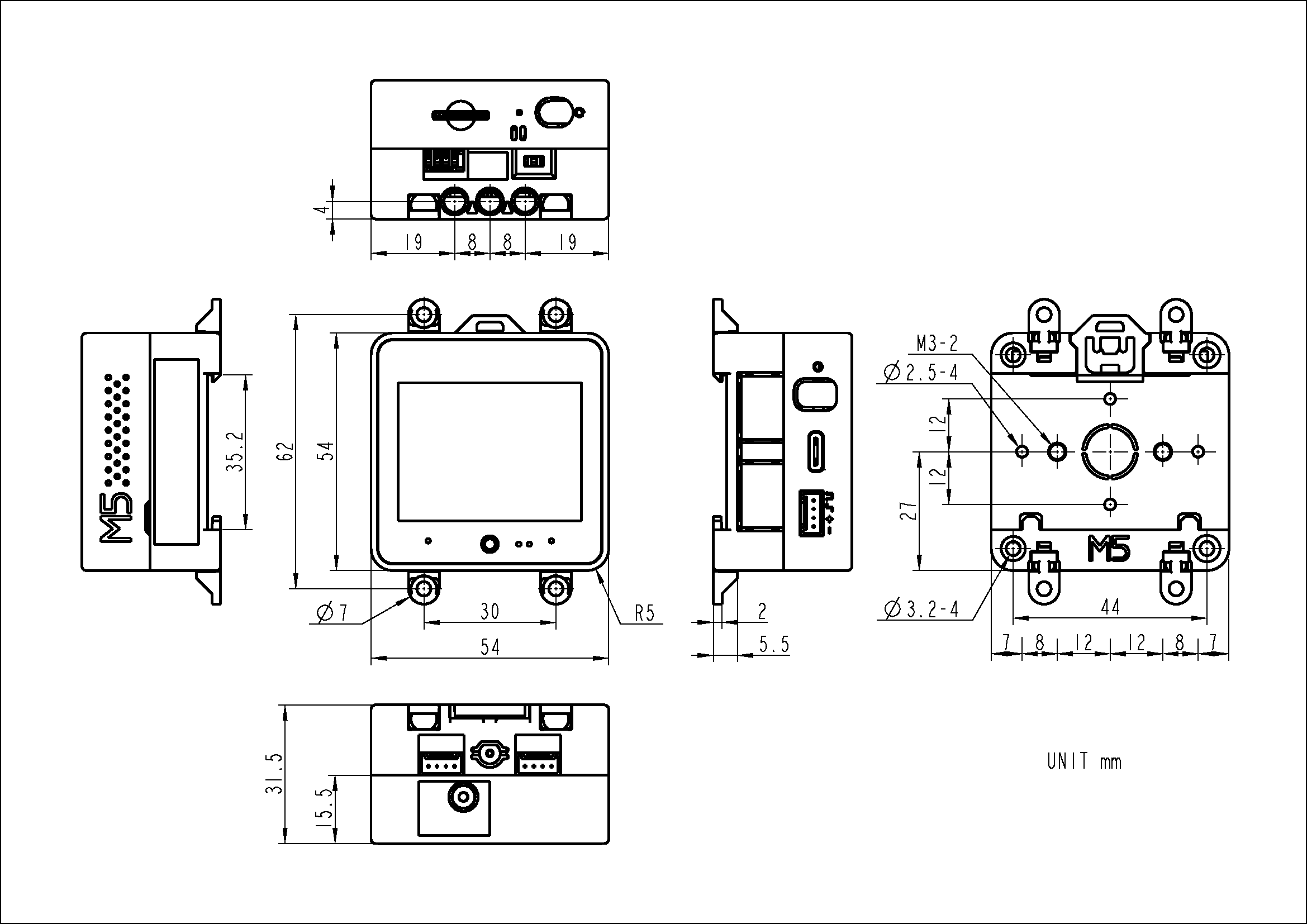
3D size source file
Datasheets
Softwares
Quick Start
Arduino
UIFlow 2.0
Platform.IO
[env:m5stack-cores3]
platform = espressif32@6.3.2
board = esp32-s3-devkitc-1
framework = arduino
upload_speed = 1500000
monitor_speed = 115200
build_flags =
    -DESP32S3
    -DBOARD_HAS_PSRAM
    -mfix-esp32-psram-cache-issue
    -DCORE_DEBUG_LEVEL=5
    -DARDUINO_USB_CDC_ON_BOOT=1
    -DARDUINO_USB_MODE=1
lib_deps =
    M5Unified=https://github.com/m5stack/M5Unified
ESP-IDF
Easyloader
| Easyloader | Download Link | Notes |
|---|---|---|
| CoreS3 Touchscreen Repair Firmware Easyloader | download | / |
| CoreS3 Factory Firmware Easyloader | download | / |
Others
- I2C Address
| Chip | ADDRESS |
|---|---|
| GC0308 ADDR | 0X21 |
| LTR553 ADDR | 0x23 |
| AXP2101 ADDR | 0x34 |
| AW88298 ADDR | 0x36 |
| FT6336 ADDR | 0x38 |
| ES7210 ADDR | 0x40 |
| BM8563 ADDR | 0x51 |
| AW9523 ADDR | 0x58 |
| BMI270 ADDR | 0x69 |
| BMM150 ADDR | 0x10 |
Video
- How to use USB port execute code on UIFlow 2.0
- Burning UIFLow2x to CoreS3
FAQ
- Q: After the sensor is connected, what is the case that the sensor does not work or does not exist?
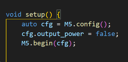
- A: The CoreS3 uses the AXP2101 power management chip, and the Port port and the M5-Bus power supply need to be configured for normal output voltage. Add M5.config() to the setup function; Will automatically configure the Unit and M5BUS output to 5V(excluding USB 5V), the sensor and base will work properly;
If you need 9-24V of the base as a power input, you need to configure cfg.output_power = false; This means that the MBUS can work properly only if it is set to the input state.
