Unit PbHub
SKU:U041


Description
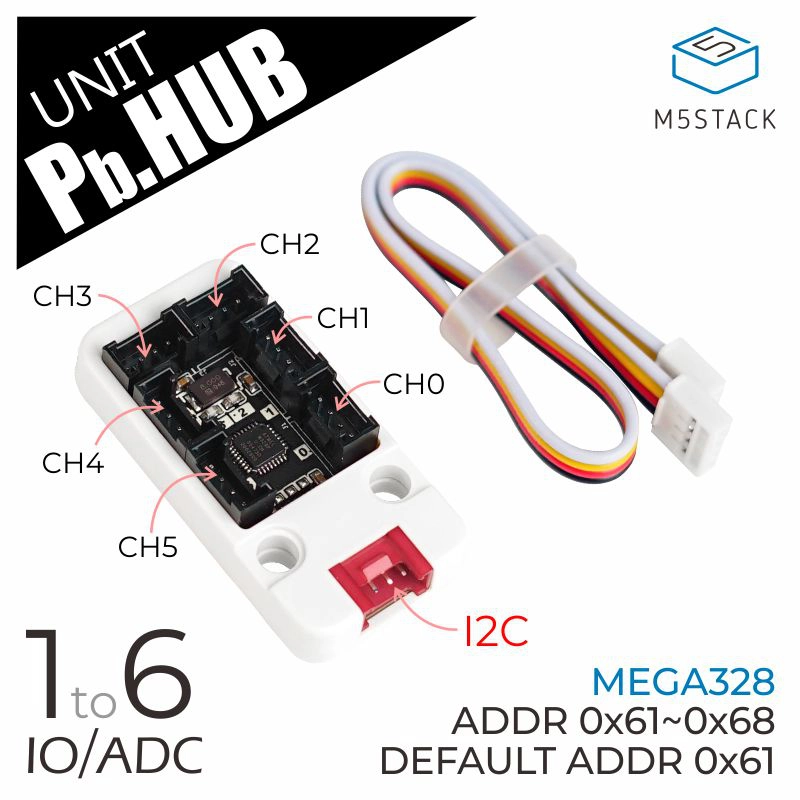
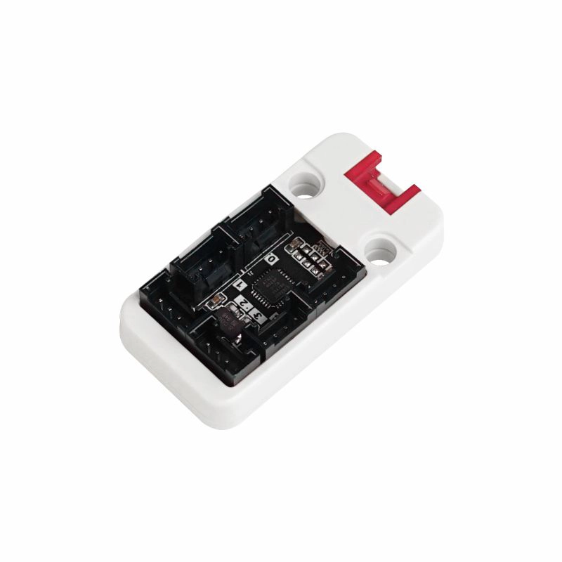
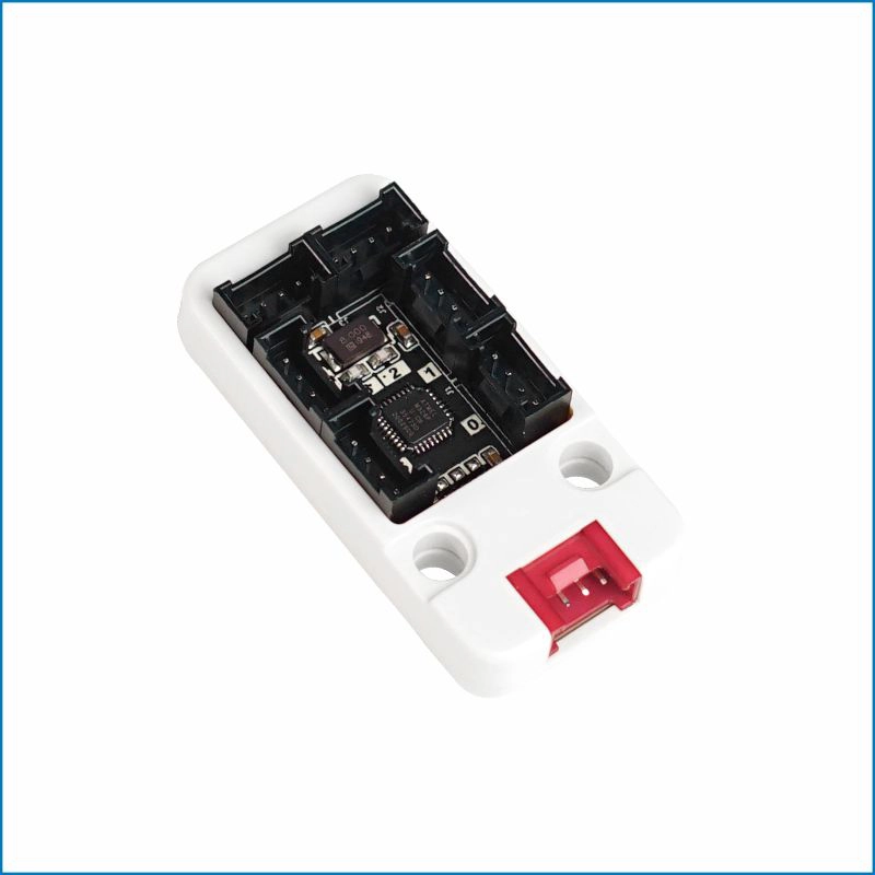
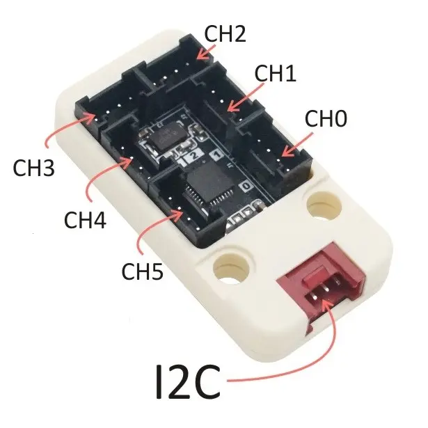
Unit PbHub is a GPIO HY2.0-4P PORTB expander that can extend a single GPIO Grove interface to six channels. It integrates an MEGA328 internally and comes with a driver. It does not support multiple Unit nesting, meaning it cannot mount multiple devices with the same protocol and address like PaHUB.
Features
- GPIO HY2.0-4P PORTB expansion
- 2 x LEGO-compatible holes
- 1-6 expansion
Includes
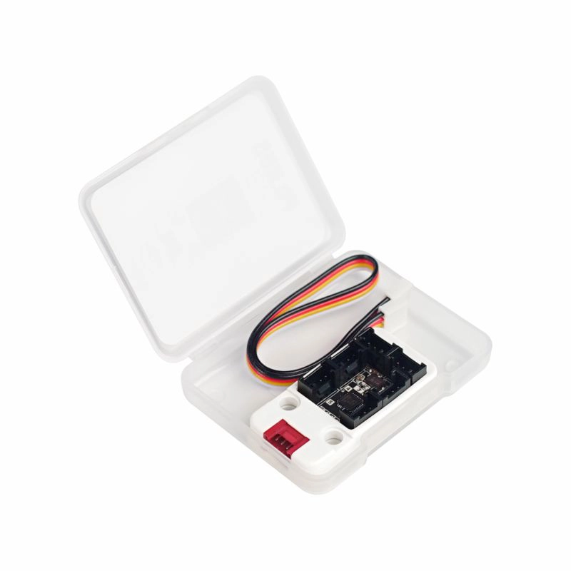
- 1 x Unit PbHub
- 1 x HY2.0-4P Grove cable (20cm)
Specifications
| Specification | Parameter |
|---|---|
| MCU | STM32F030F4P6 |
| Protocol | I2C @0x61 (modifiable via resistors A0, A1, A2) |
| Product Size | 48.0 x 24.0 x 10.8mm |
| Product Weight | 7.1g |
| Package Size | 138.0 x 93.0 x 11.8mm |
| Gross Weight | 12.4g |
Learn
Note
1. The default ADC input voltage range of the built-in MCU is 0-5V, with a corresponding ADC resolution of 10bit (1024). Therefore, when using an analog signal input with a range less than 5V, the maximum value of 1024 cannot be reached.
2. Not all Units with black interfaces (PortB) support expansion via PbHUB. PbHUB can only be used for basic single-bus communication. Through the I2C protocol (built-in MEGA328), it can achieve basic digital and analog read/write operations. However, for Units like Weight (built-in HX711) that require not only analog reading but also timing-dependent communication, PbHUB cannot be used for expansion.
3. The two data buses in Port B are connected to G36 and G26 of the ESP32, allowing for programming configuration of multiple ports for input (supports analog input) and output as needed.
Modifying I2C Address
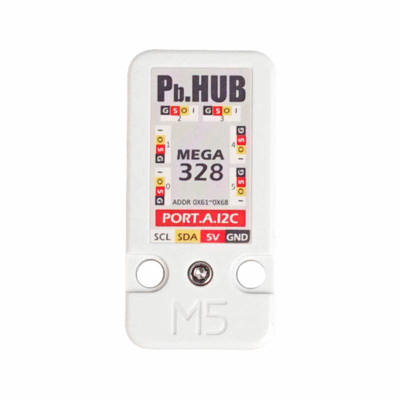
The I2C address of this Unit is 0x61 (can be changed by soldering resistors A0 ~ A2, with an address range of 0x61 ~ 0x68).
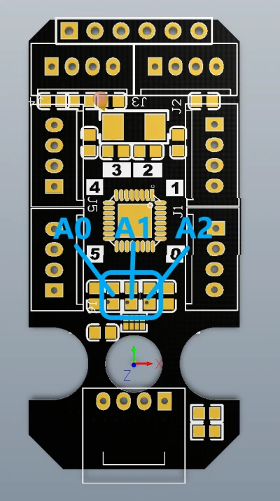
| A0 | A1 | A2 | I2C Address |
|---|---|---|---|
| / | / | / | 0x61 |
| Soldered | / | / | 0x62 |
| / | Soldered | / | 0x63 |
| Soldered | Soldered | / | 0x64 |
| / | / | Soldered | 0x65 |
| Soldered | / | Soldered | 0x66 |
| / | Soldered | Soldered | 0x67 |
| Soldered | Soldered | Soldered | 0x68 |
Schematics
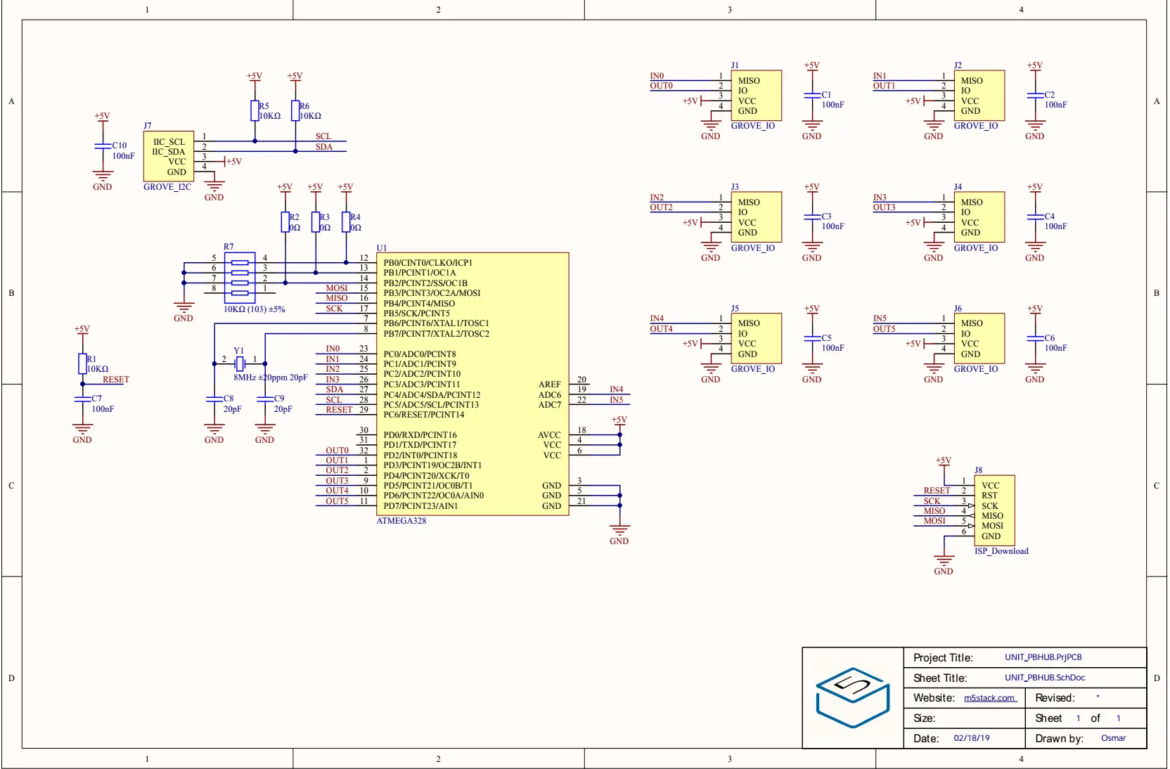
PinMap
Unit PbHub
| HY2.0-4P | Black | Red | Yellow | White |
|---|---|---|---|---|
| PORT.A | GND | 5V | SDA | SCL |
Mega328 ISP Download Interface Pin Definition
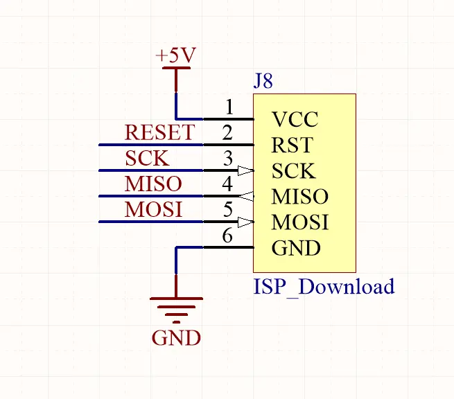
Softwares
Arduino
UiFlow1
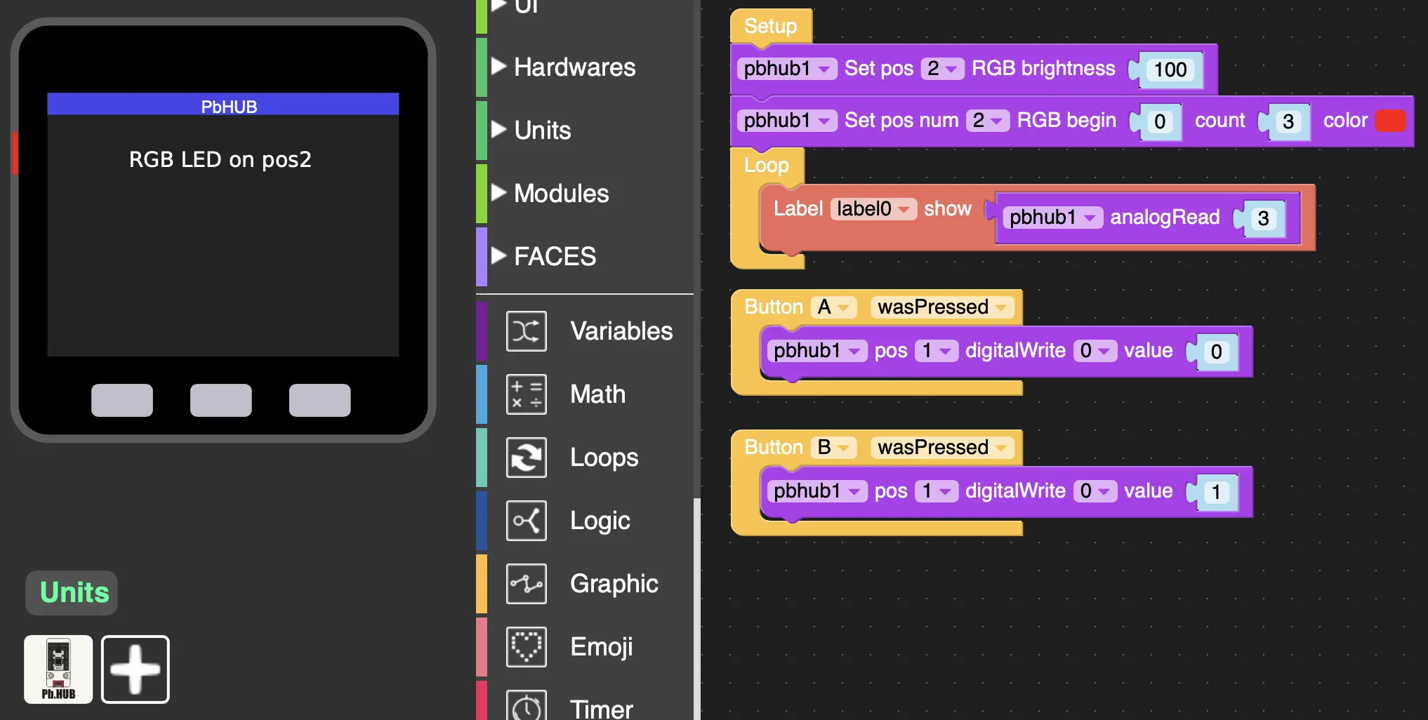
Protocol
| state | IO0 Digital Write | IO1 Digital Write | IO0 Analog Write | IO1 Analog Write | IO0 Digital Read | IO1 Digital Read | IO0 Analog Read | reserve | Set RGB LED Num | Set oneLED Color* | Set moreLED Color* | Set Brightness |
|---|---|---|---|---|---|---|---|---|---|---|---|---|
| r/w | w | w | w | w | r | r | r | r | w | w | w | w |
| data length (Byte) | 1 | 1 | 1 | 1 | 1 | 1 | 2 | / | 2 | 5 | 7 | 1 |
| ch0 cmd | 40 | 41 | 42 | 43 | 44 | 45 | 46 | 47 | 48 | 49 | 4A | 4B |
| ch1 cmd | 50 | 51 | 52 | 53 | 54 | 55 | 56 | 57 | 58 | 59 | 5A | 5B |
| ch2 cmd | 60 | 61 | 62 | 63 | 64 | 65 | 66 | 67 | 68 | 69 | 6A | 6B |
| ch3 cmd | 70 | 71 | 72 | 73 | 74 | 75 | 76 | 77 | 78 | 79 | 7A | 7B |
| ch4 cmd | 80 | 81 | 82 | 83 | 84 | 85 | 86 | 87 | 88 | 89 | 8A | 8B |
| ch5 cmd | A0 | A1 | A2 | A3 | A4 | A5 | A6 | A7 | A8 | A9 | AA | AB |
EasyLoader
| Easyloader | Download Link | Note |
|---|---|---|
| Unit PbHub Test Easyloader | download | / |