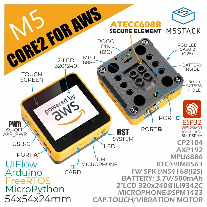
Core2 for AWS is a dedicated kit for AWS IoT learning projects. It consists of the M5Stack Core2 main control unit and the M5GO-Bottom For AWS expansion base, with an additional custom integration of the ATECC608 Trust&GO hardware encryption, making it an ideal kit for IoT learning and secure project development.
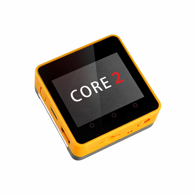
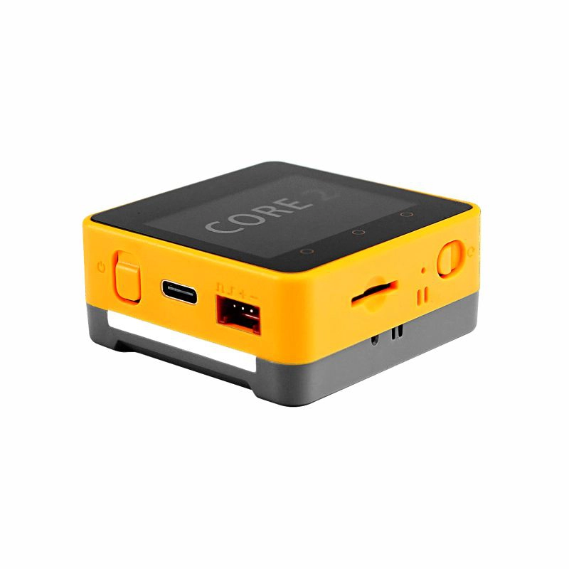
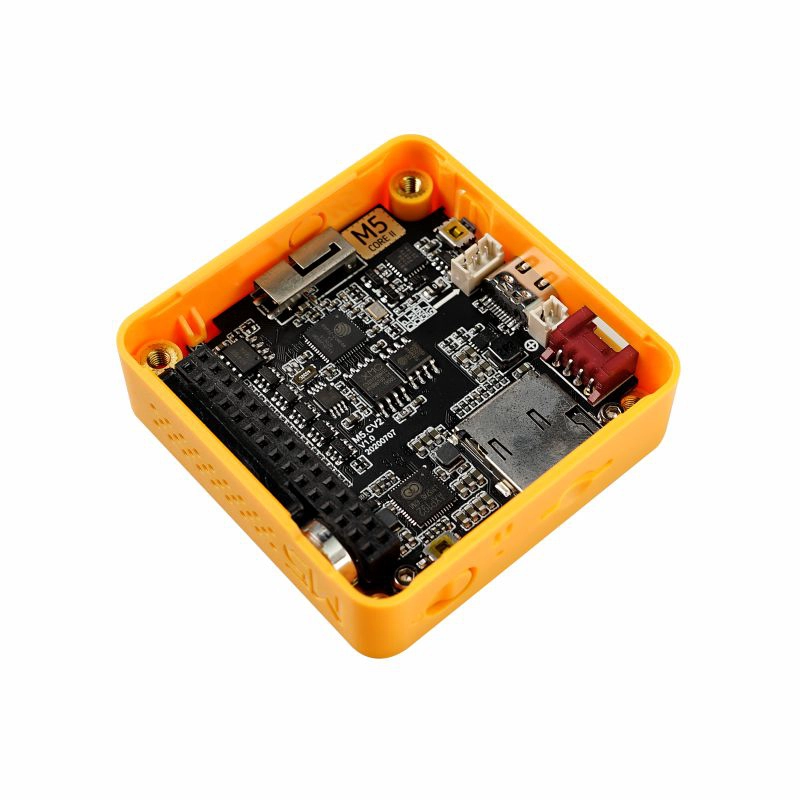
The main control unit Core2 is equipped with the ESP32-D0WDQ6-V3, featuring two independently controllable Xtensa® 32-bit LX6 processors with a clock speed of up to 240MHz, supporting WiFi functionality. It comes with 16MB Flash and 8MB PSRAM, and programs can be downloaded via the TYPE-C interface. The robust configuration meets the resource demands of complex applications. The front features a 2.0-inch integrated capacitive touchscreen, providing a smoother human-machine interaction experience. The device includes a built-in vibration motor for tactile feedback and vibration alerts. The built-in RTC module offers precise timing functions. The power section is equipped with the AXP192 power management chip, effectively controlling power consumption, and includes a green power indicator. The device also features a TF-card (microSD) slot and a speaker. To ensure higher-quality sound, an I2S digital audio interface amplifier chip is used, effectively preventing signal distortion. The left side and bottom of the device have independent power and reset (RST) buttons. The three dots on the front of the screen are part of the touchscreen and can be programmed as three virtual buttons.
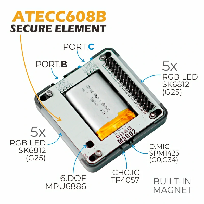
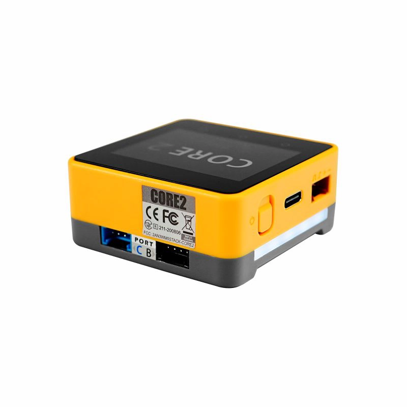
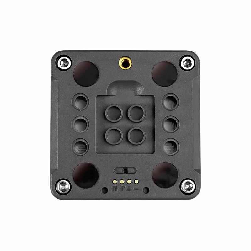
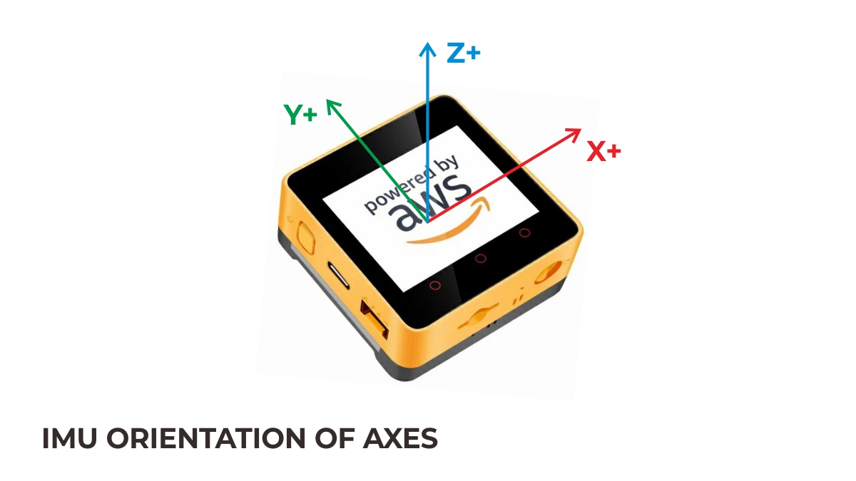
M5GO-Bottom For AWS is an expansion base specifically designed for this custom model. The base integrates an MPU6886 six-axis motion sensor, a digital microphone (SPM1423), and a 500mAh lithium battery. It provides two HY2.0-4P expansion interfaces, exposing commonly used ADC/DAC/UART pins for connecting various sensors. The sides of the base feature 10 programmable RGB LEDs (SK6812), paired with frosted light-transmitting material, providing a soft and comfortable lighting effect. The bottom uses a pogo pin magnetic charging interface. When attached to the charging base, current flows safely into the internal battery via the built-in TP4057 charging chip. In addition to charging, the pogo pin interface exposes the main control I2C bus, allowing for magnetic attachment of external expansions. The base includes built-in magnets and a LEGO-compatible hole design on the back, enabling seamless integration with other LEGO structures. The PCB of Core2 for AWS reserves interfaces for the CP2104 chip and the lithium battery.
The AWS custom model embeds the ATECC608 hardware encryption chip, enhancing the security of IoT communication at the hardware level.
This tutorial shows how to program and control the Core2 for AWS device using the Arduino IDE.
Notes
The built-in vibration motor of M5Core2 interferes structurally with the M5 Base series bases. To prevent equipment damage, do not stack M5Core2 with any M5 Base series functional bases.
Some screens may exhibit non-linear touch response at the edges. You can try upgrading the screen firmware using M5Tool to resolve this issue.
Features
Based on ESP32, supports WiFi
Built-in ATECC608 hardware encryption chip
16MB Flash, 8MB PSRAM
Built-in speaker, power indicator, vibration motor, RTC, I2S amplifier, capacitive touchscreen, power button, reset button
TF card slot (supports up to 16GB)
Built-in lithium battery with power management chip
Built-in 6-axis IMU, PDM microphone
M5-Bus socket
Development Platform
UiFlow1
UiFlow2
Arduino IDE
ESP-IDF
PlatformIO
Includes
1 x M5Stack Core2
1 x M5GO Bottom2 for AWS
1 x USB Type-C cable (50cm)
1 x Hex wrench
Applications
IoT controller
STEM education
DIY projects
Specifications
Specification
Parameter
SoC
ESP32-D0WDQ6-V3 @ Dual-core processor, 240MHz main frequency
DMIPS
600
SRAM
520KB
Flash
16MB
PSRAM
8MB
Wi-Fi
2.4 GHz Wi-Fi
Hardware Encryption Chip
ATECC608B-TNGTLSU-G (addr 0x35)
Input Voltage
5V @ 500mA
Host Interface
Type-C x1, POGO PIN x1, I2C x1, GPIO x1, UART x1
Programmable LED
SK6812*10
Button
Power button, RST button, screen virtual buttons * 3
Vibration Alert
Vibration motor
IPS LCD Screen
2.0"@320 x 240 ILI9342C
Capacitive Touch IC
FT6336U
Speaker
1W-0928
Microphone
SPM1423
I2S Amplifier
NS4168
IMU
MPU6886
RTC
BM8563
PMU
AXP192
USB Chip
CP2104
DC-DC Boost
SY7088
TF Card Slot
Supports up to 16G
Lithium Battery
500mAh @ 3.7V
Antenna
2.4G 3D antenna
Operating Temperature
0 ~ 40°C
Case Material
Plastic ( PC )
Product Size
54.0 x 54.0 x 23.5mm
Product Weight
69.5g
Package Size
90.0 x 60.0 x 30.0mm
Gross Weight
110.0g
Learn
Power Management
Power On: Click the power button on the left side
Power Off: Long press the power button on the left side for 6 seconds
Click the link below to download the driver that matches the operating system. There are currently two driver chip versions, CP210X (for CP2104 version)/CP34X (for CH9102 version) driver compressed package. After decompressing the compressed package, select the installation package corresponding to the number of operating systems to install. (If you are not sure of the USB chip used by your device, you can install both drivers at the same time. During the installation process of CH9102_VCP_SER_MacOS v1.7, an error may occur, but the installation is actually completed, just ignore it.) When using it, if If the program cannot be downloaded normally (the prompt is overtime or Failed to write to target RAM), you can try to reinstall the device driver.
To compare information on the controller series products, you can visit the Product Selection Table, check the target products, and get the comparison results. The selection table covers key information such as core parameters and functional features, and supports comparison of multiple products simultaneously.