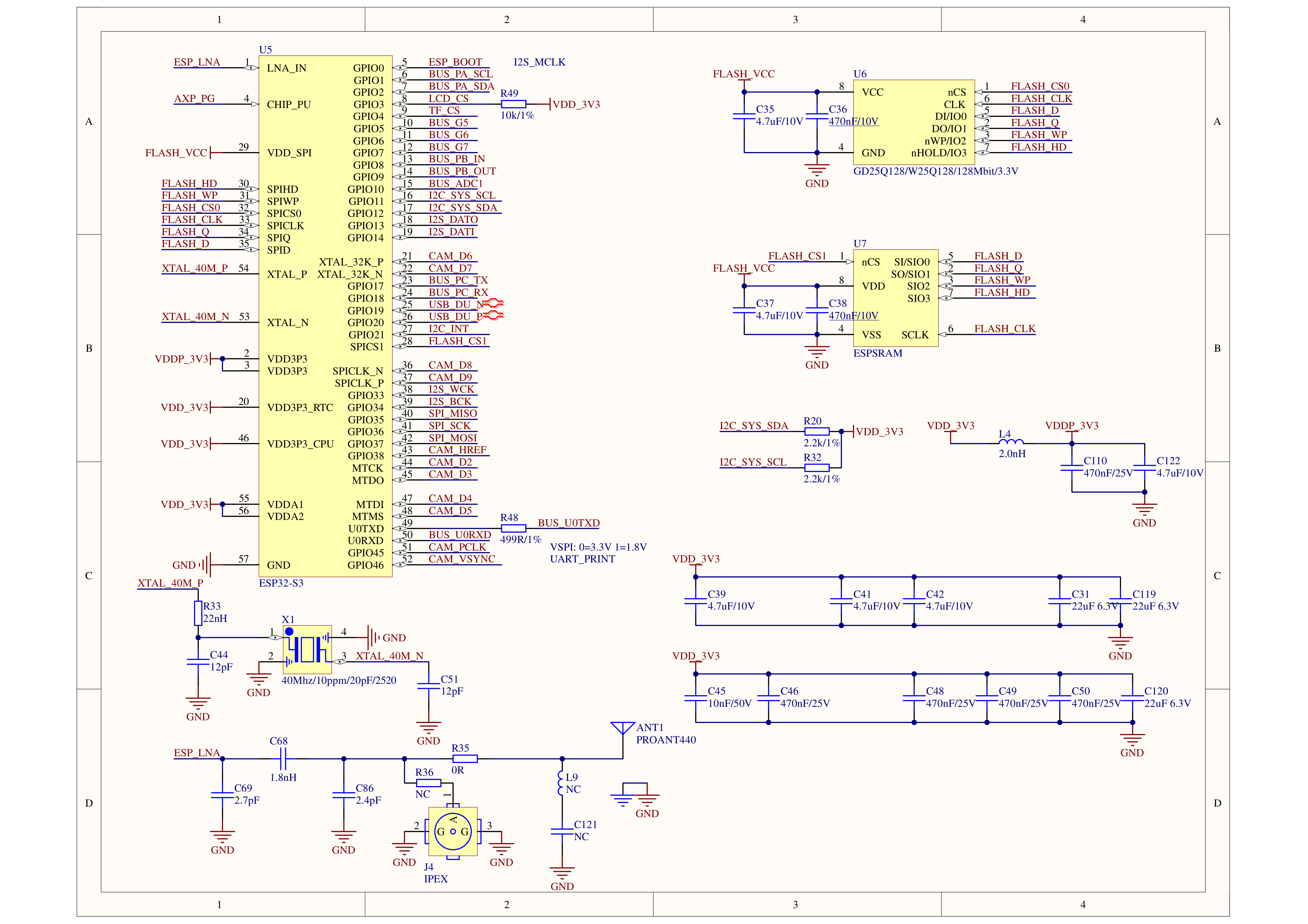
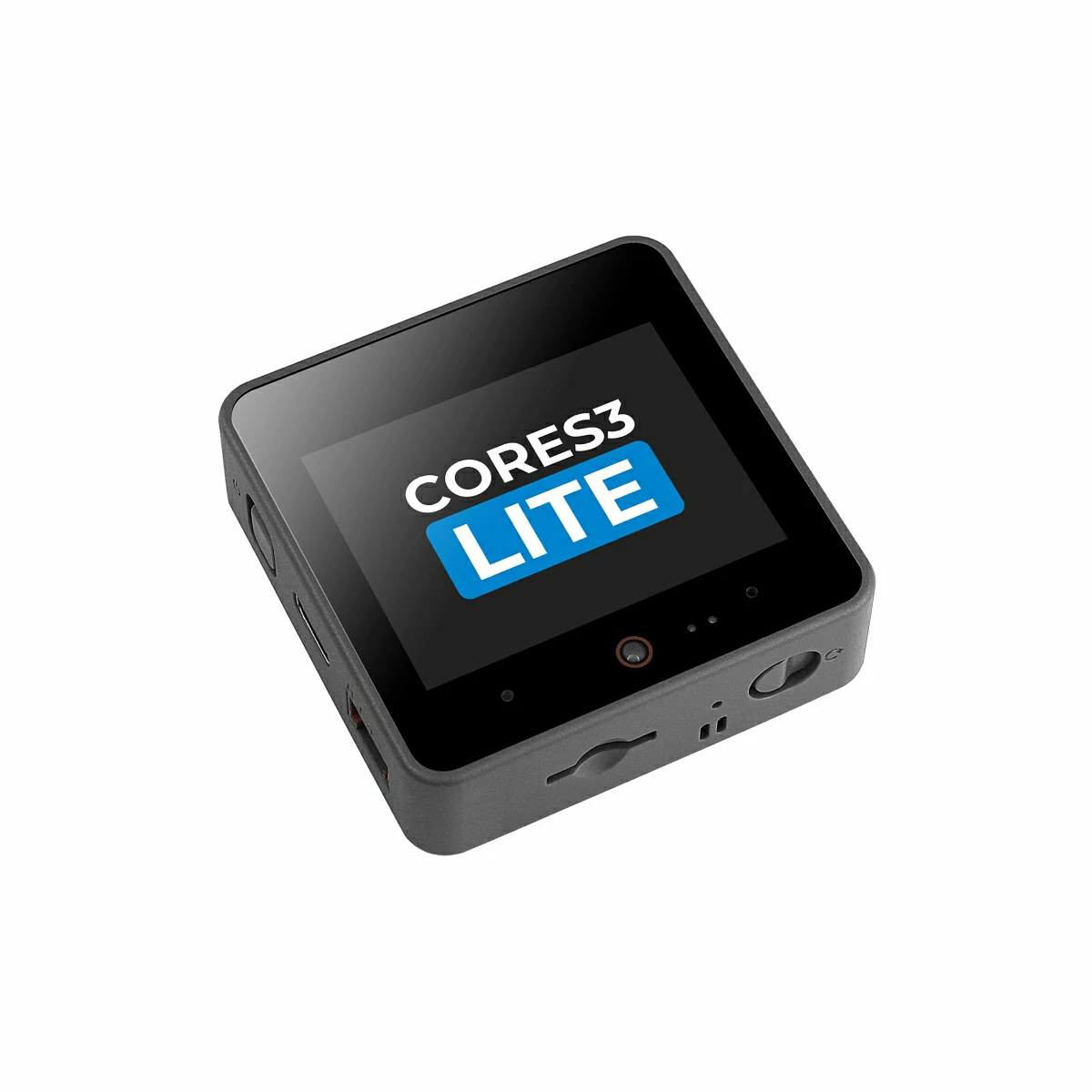
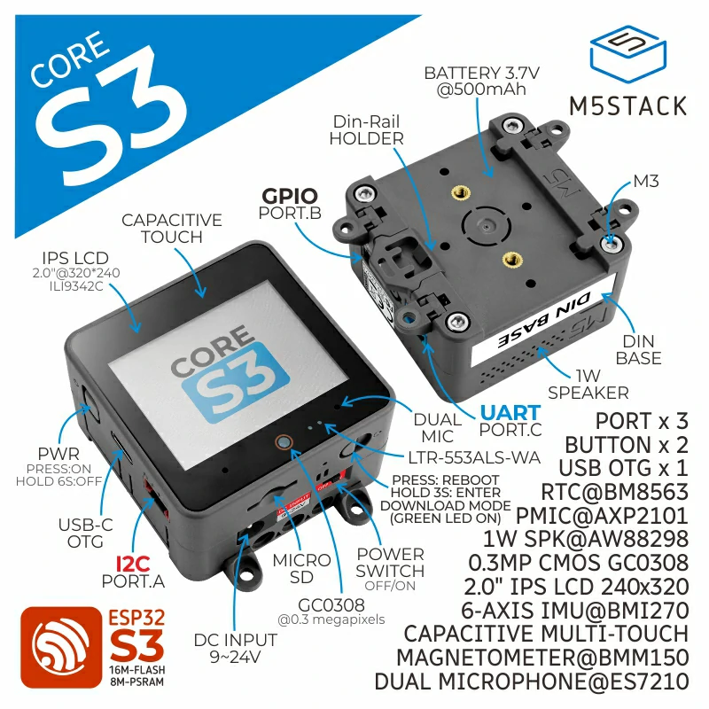
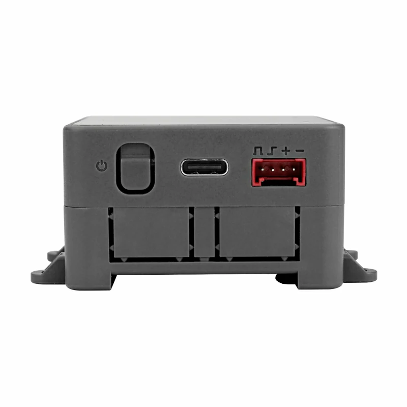
CoreS3 is the third-generation main controller of the M5Stack development kit series, based on the ESP32-S3 solution featuring a dual-core Xtensa LX7 processor running at 240 MHz with built-in Wi-Fi. It integrates 16MB Flash and 8MB PSRAM. Programs can be downloaded through the USB Type-C port, and OTG & CDC functions are supported for connecting USB devices and flashing firmware.
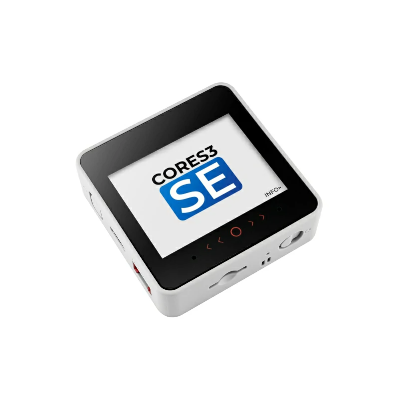
The front houses a 2.0-inch capacitive-touch IPS panel protected by high-strength glass. Below the screen is a 0.3MP GC0308 camera paired with an LTR-553ALS-WA proximity sensor. Power is managed by an AXP2101 PMU and four power-path control circuits, delivering a low-power design. Onboard sensors include a six-axis IMU BMI270 and a magnetometer BMM150. Additional peripherals comprise a microSD slot and a BM8563 RTC, enabling precise time-keeping plus sleep/timed-wake-up functions.
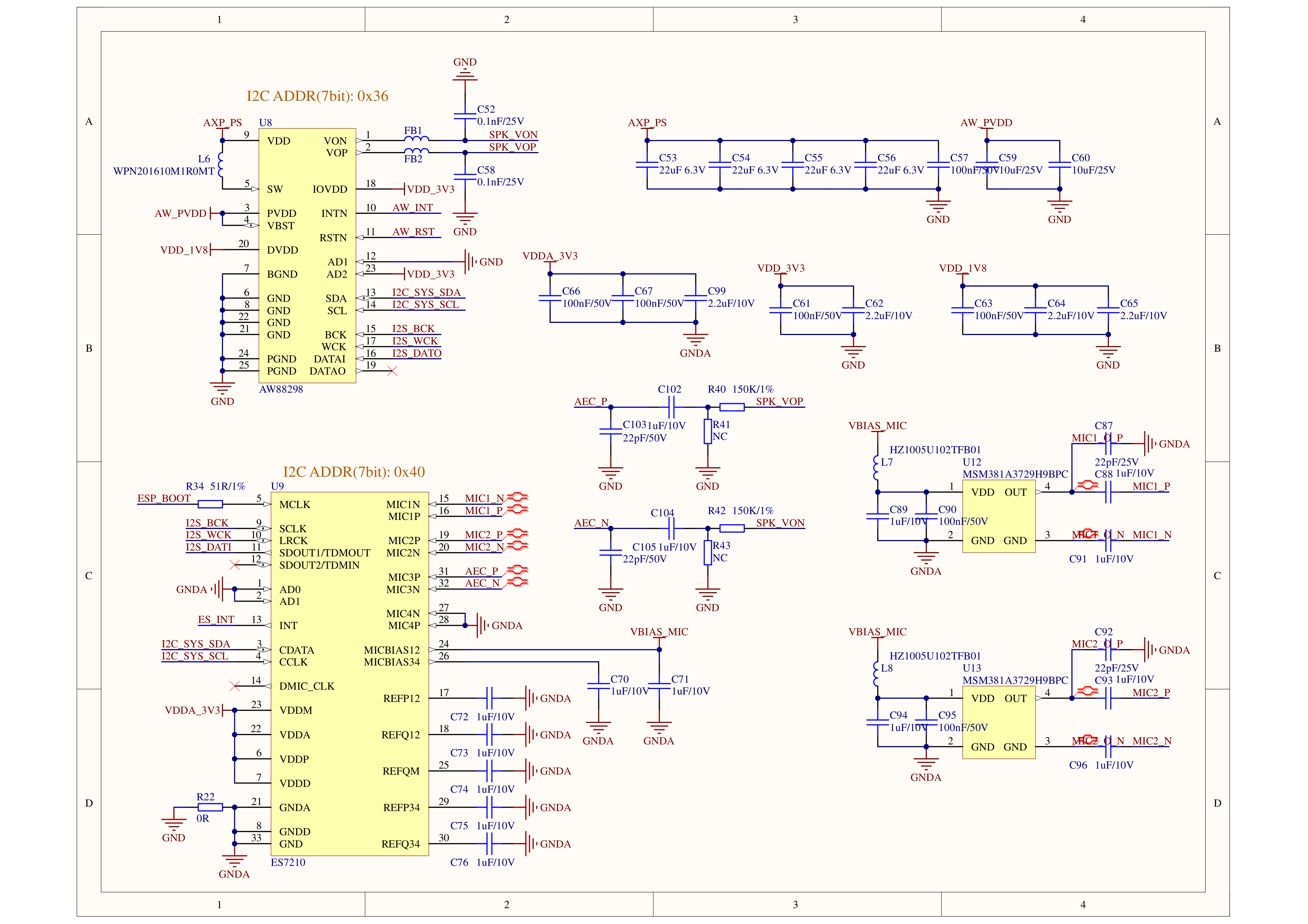
For audio, a 16-bit I2S amplifier AW88298 drives the built-in 1W speaker, while an ES7210 audio codec provides dual-microphone input. Independent POWER and RESET (RST) buttons are located on the side; long-pressing the RESET button enters download mode via a self-built delay circuit.
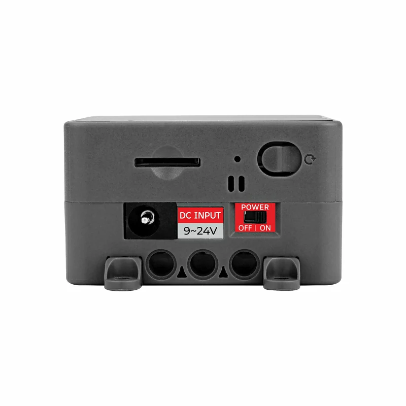
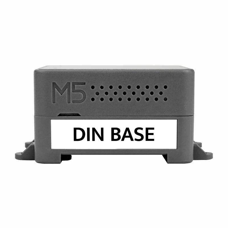
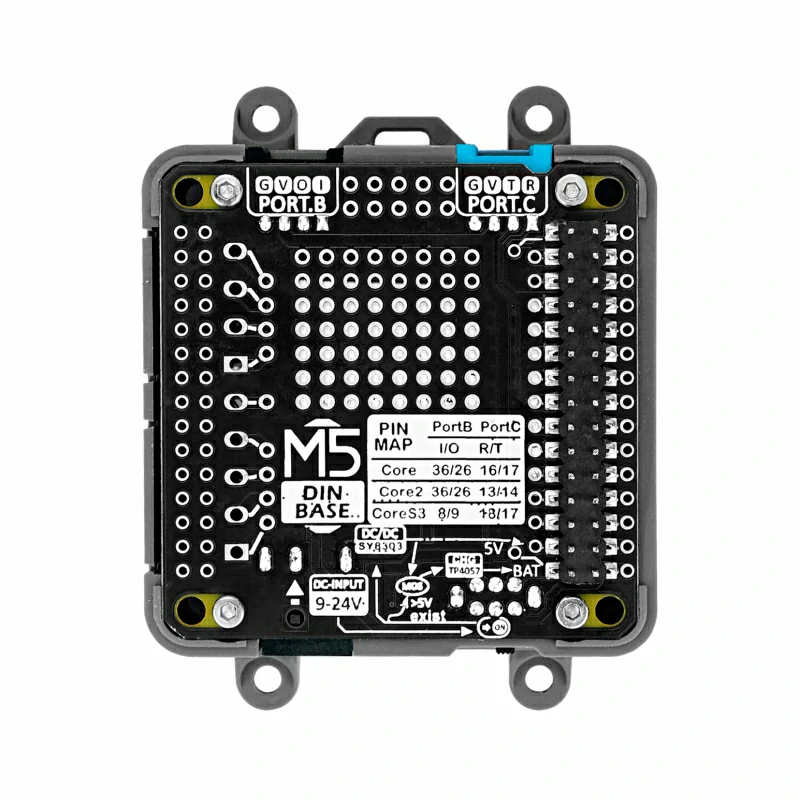
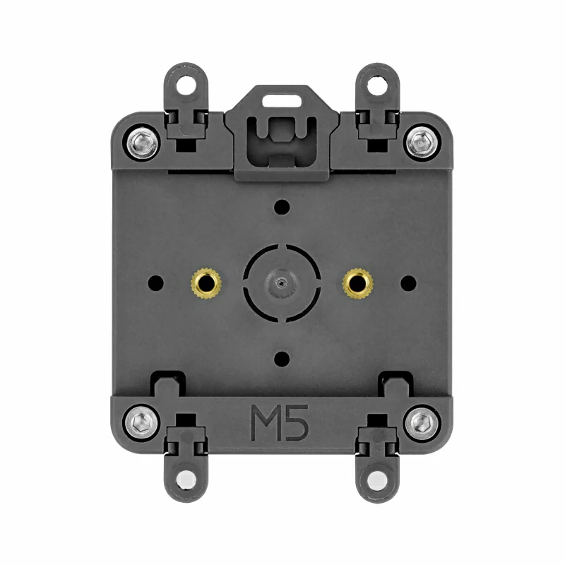
The kit ships with a DinBase for DIN-rail, wall-mount or screw mounting. It can be powered by an external DC 12V (9 ~ 24V) supply or an internal 500mAh battery. Multiple proto areas on the DinBase ease DIY expansion.
Ideal for IoT development, DIY projects, smart-home control systems and industrial automation control systems.
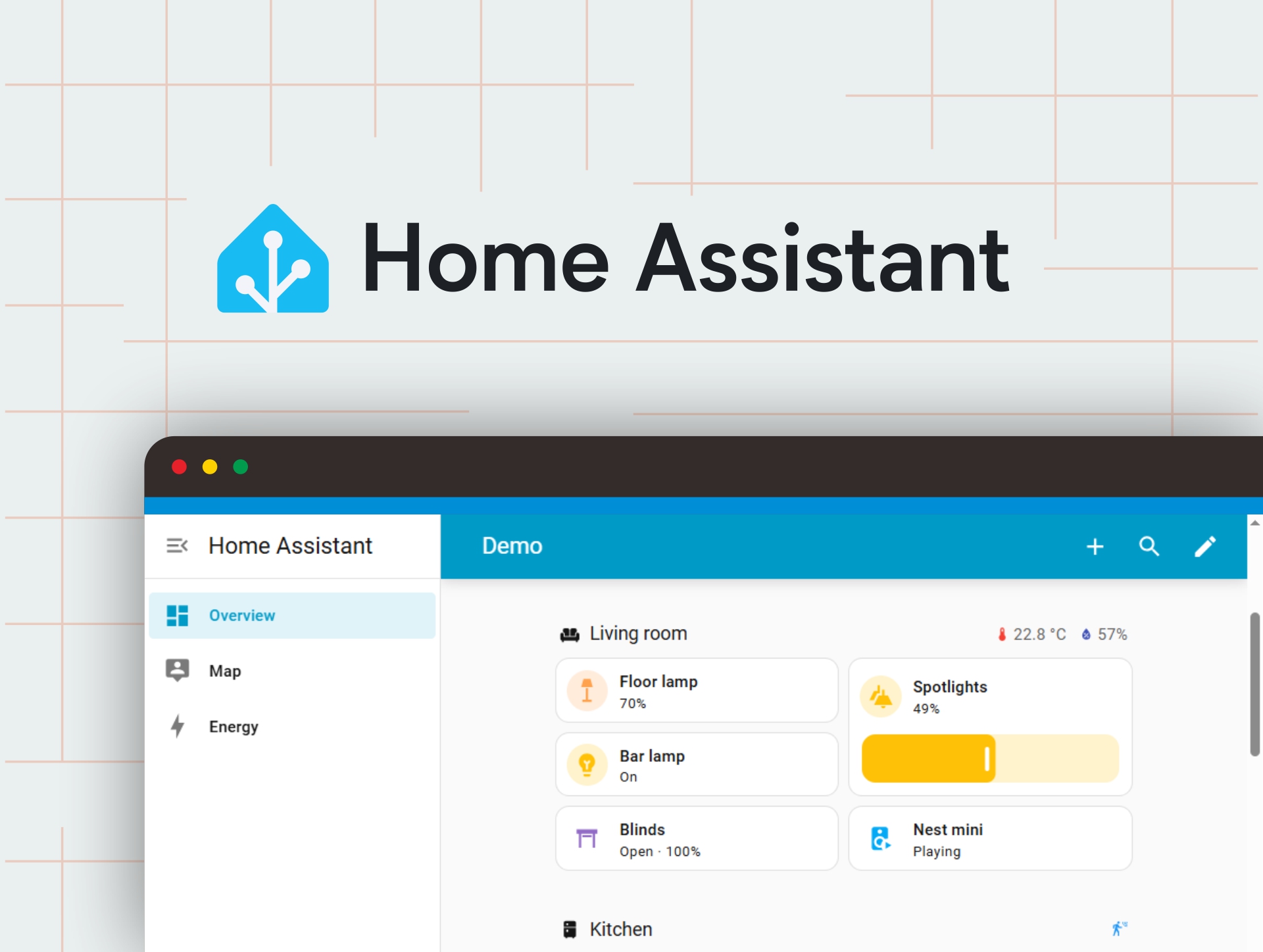
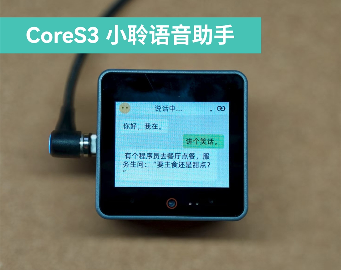
This tutorial will introduce how to use the CoreS3 controller to burn the Xiaoling Voice Assistant firmware via M5Burner and build a personal voice assistant application.
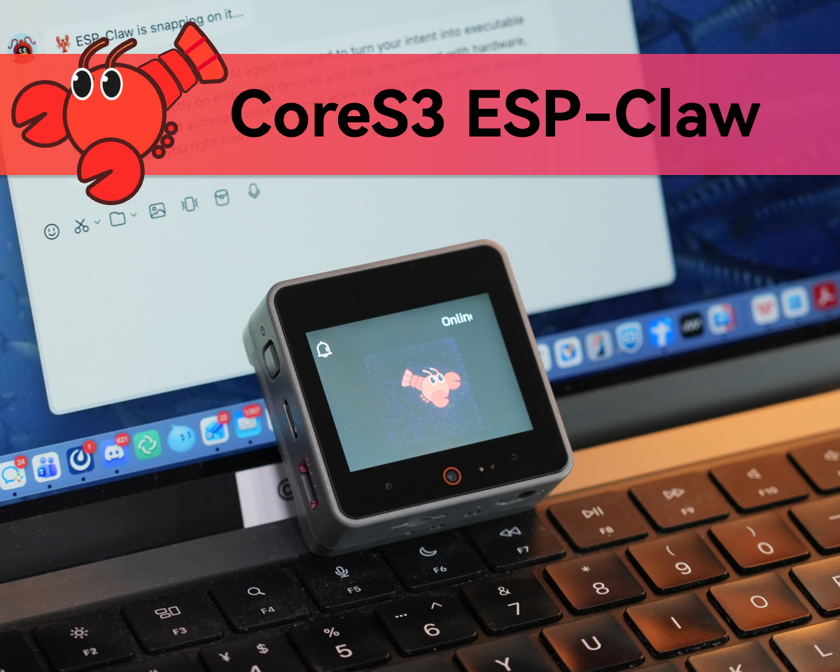
This tutorial explains how to flash the ESP-Claw firmware onto the CoreS3, enabling users to quickly configure their CoreS3 as an intelligent terminal capable of AI interaction, hardware programming, and automation control.
ESP32-S3 @ Dual-core Xtensa LX7 processor, 240MHz main frequency
Flash
16MB
PSRAM
8MB Quad
Wi-Fi
2.4 GHz Wi-Fi
Touch IPS LCD
2.0" @320 × 240 ILI9342C
Camera
GC0308 0.3MP
Proximity Sensor
LTR-553ALS-WA
Power Management
AXP2101
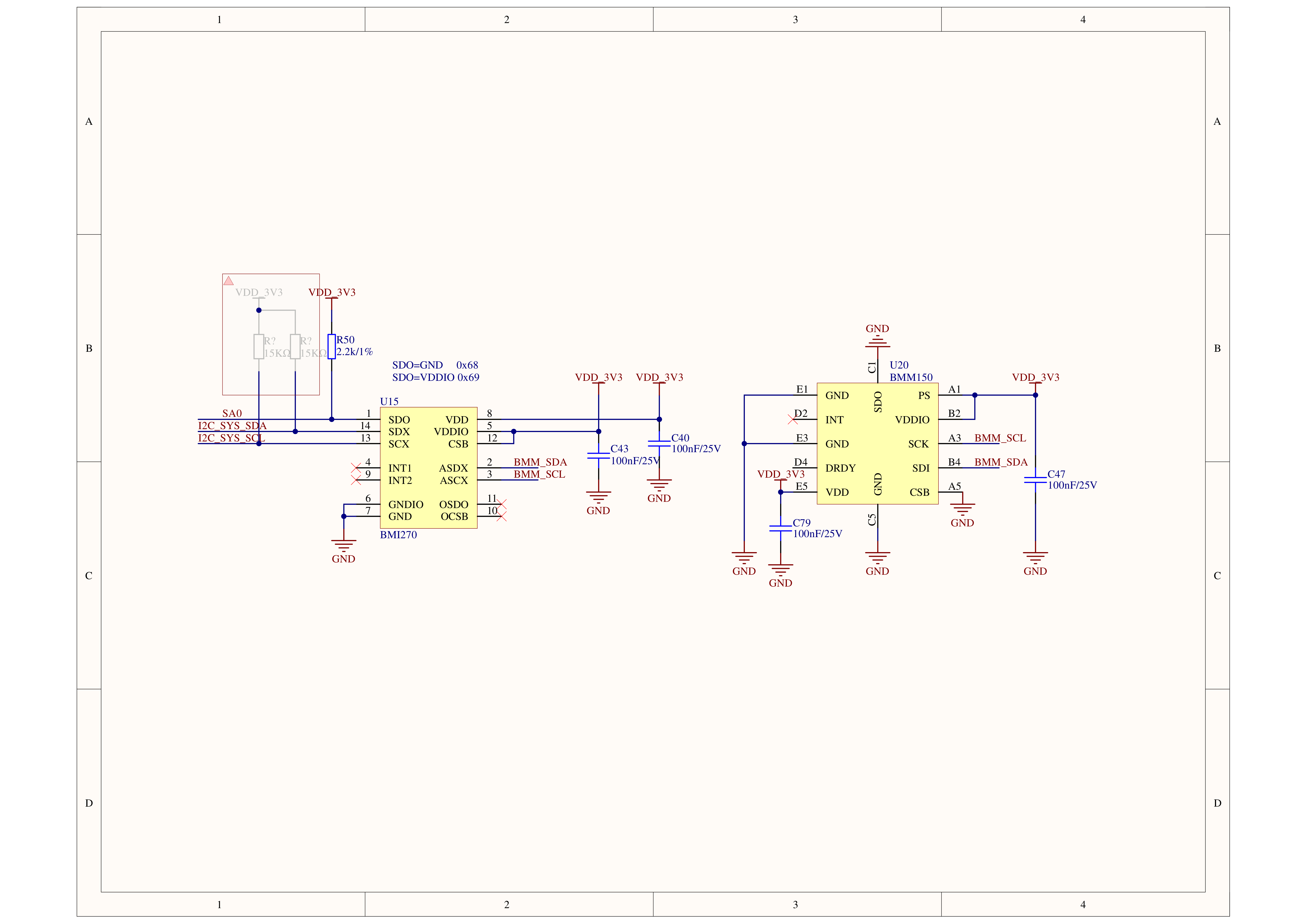
6-axis IMU
BMI270
3-axis Magnetometer
BMM150
RTC
BM8563
Speaker
16-bit I2S amplifier AW88298 @1W
Audio Codec
ES7210, dual-microphone input
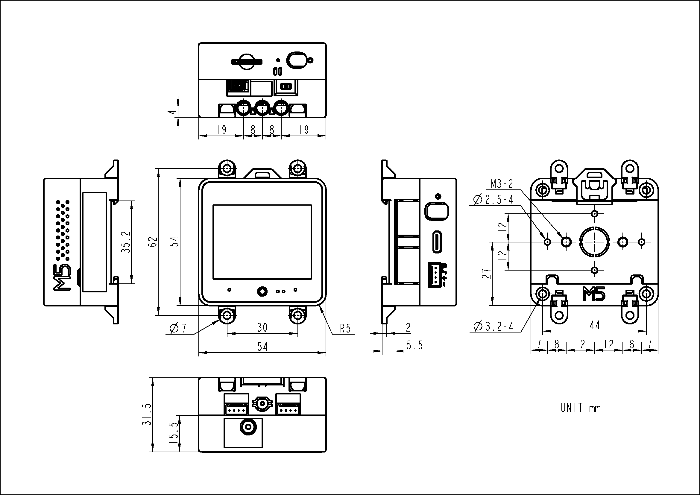
Product Size
Whole set (CoreS3+DinBase): 69.0 × 54.0 × 31.5mm Main unit (CoreS3): 54.0 × 54.0 × 15.5mm
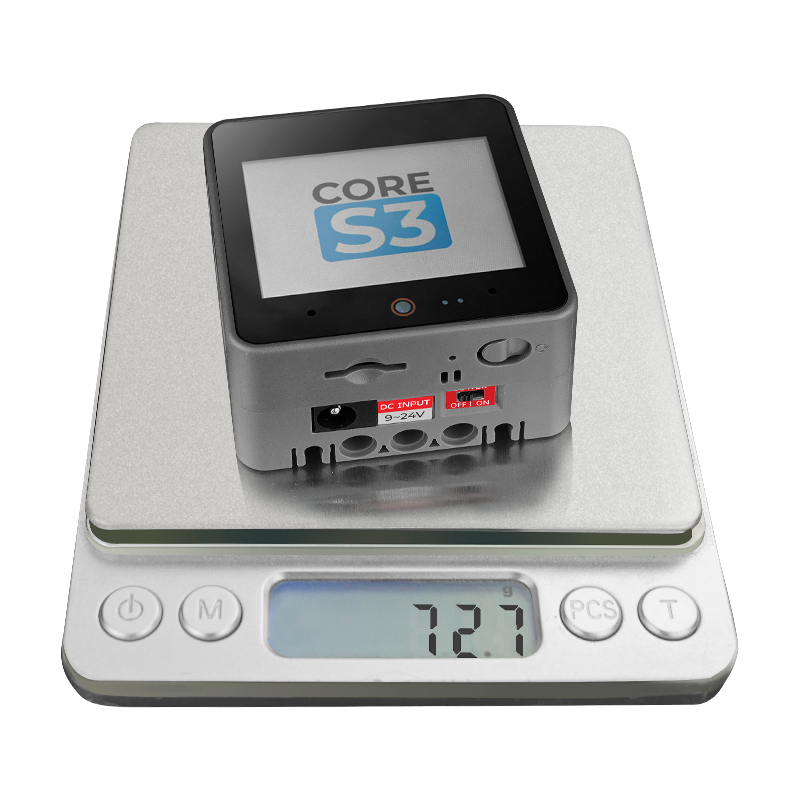
Product Weight
72.7g
Package Size
105.6 × 66.0 × 35.3mm
Gross Weight
101.8g
Learn
BMM150 Magnetic Interference
Products containing magnets may interfere with the BMM150 magnetic sensor, resulting in abnormal readings. When used with M5 controllers that have magnets, remove the magnets and avoid placing the BMM150 near strong magnetic fields.
Download Mode
Long-press the RESET button for 3 s (green LED on) to enter download mode before flashing firmware.
Power On/Off
Power-on: single-click the left POWER button
Power-off: long-press the left POWER button for 6 s
Reset: single-click the bottom RST button
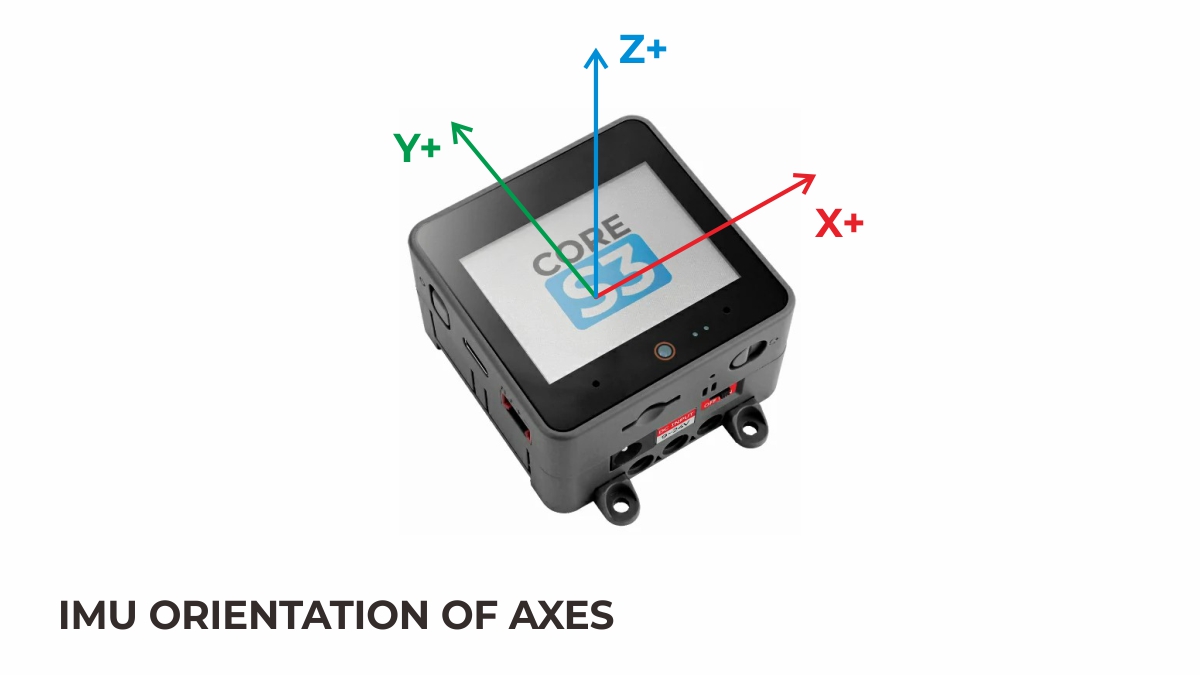
IMU Triaxial Direction Schematic Diagram
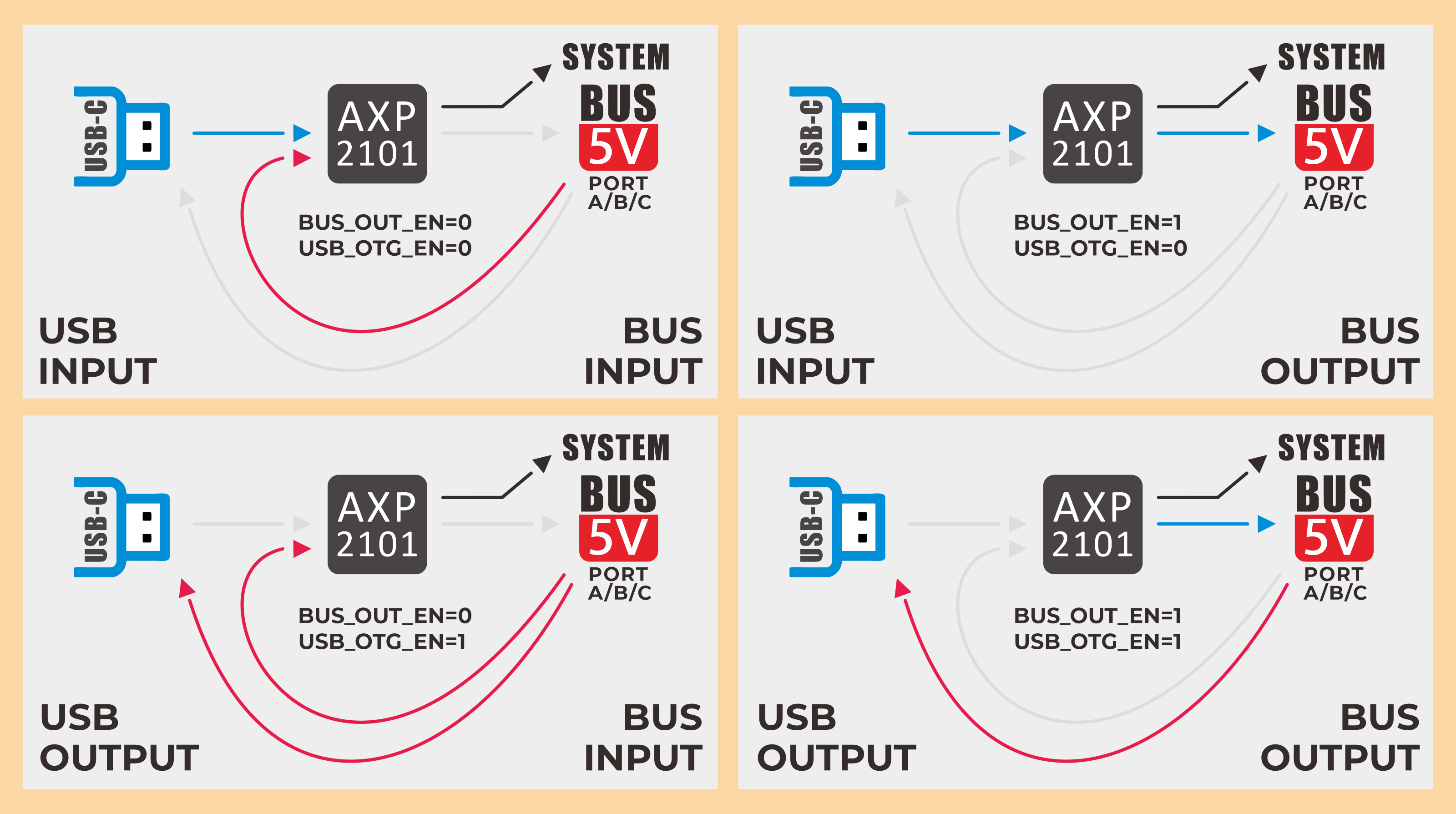
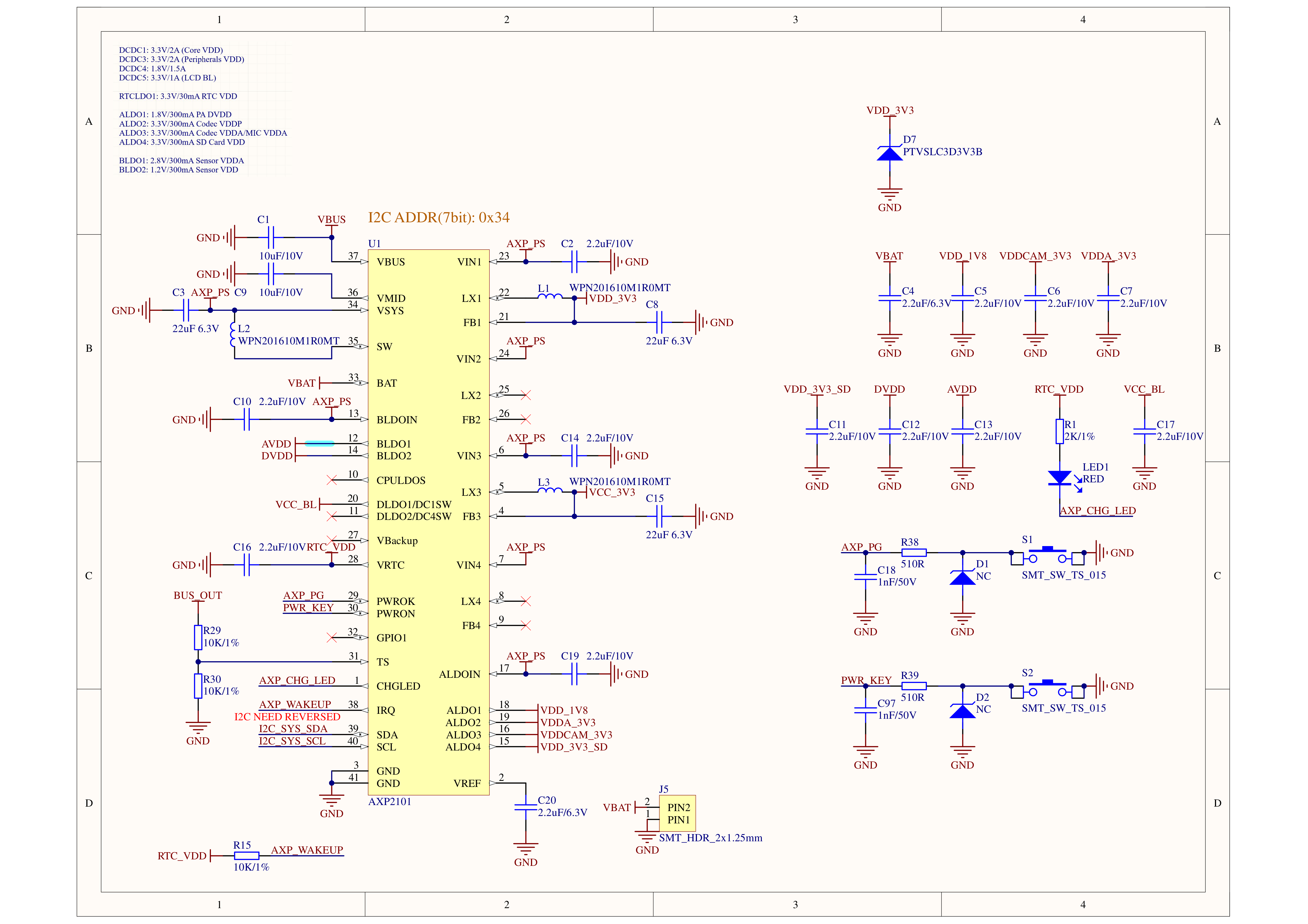
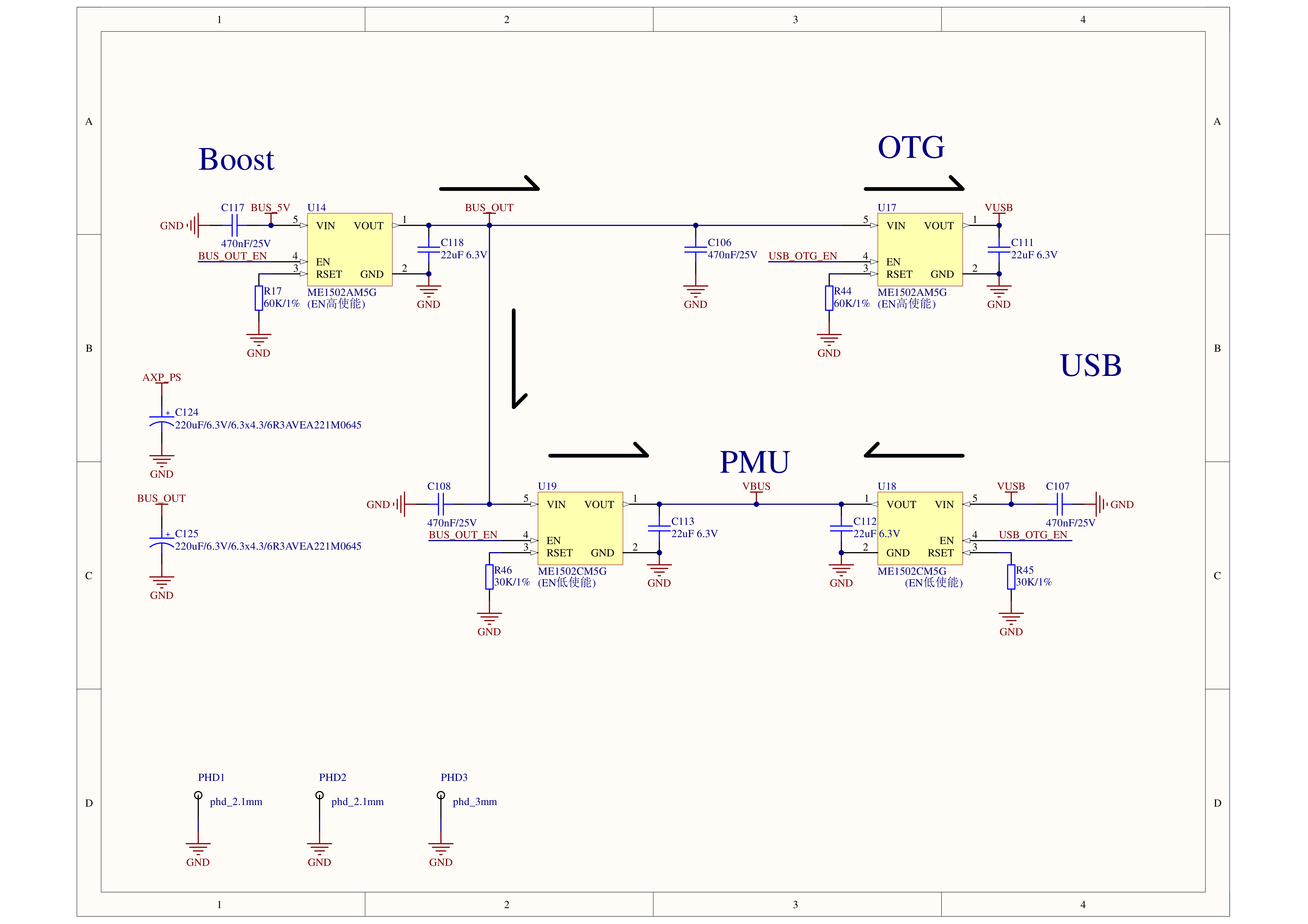
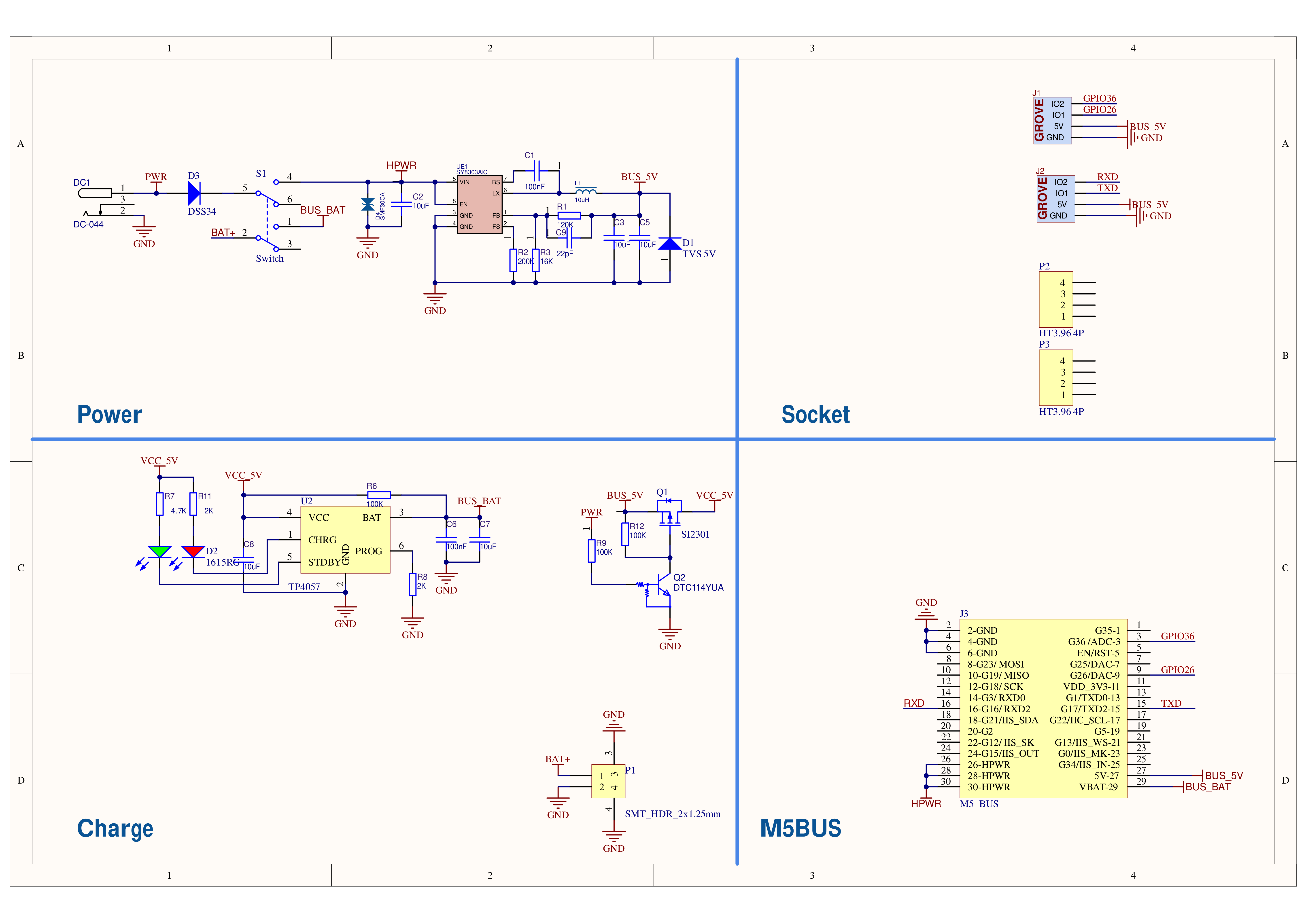
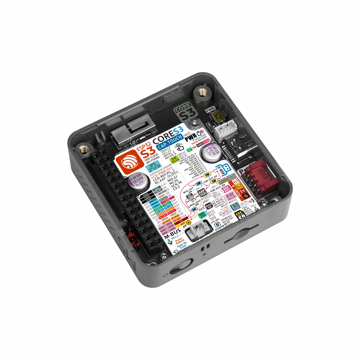
Power Management
CoreS3 uses the AXP2101 PMU together with the AW9523B IO expander to control power input/output directions. Refer to the pin states of BUS_OUT_EN and USB_OTG_EN in the figure below and check the example code in CoreS3 Power Manager Example。
The LTR-553ALS-WA proximity sensor and the camera are integrated on one ribbon cable, and use I2C for communication. Please refer to the table above for detailed communication addresses.
To compare information on the controller series products, you can visit the Product Selection Table, check the target products, and get the comparison results. The selection table covers key information such as core parameters and functional features, and supports comparison of multiple products simultaneously.


.gif)