StackFlow AI Platform
Devices & Quick Start
Models
Qwen3
DeepSeek-R1
AI Pyramid Applications
Module LLM Applications
CV Vision Application
Vision Language Model (VLM)
Large Language Model (LLM)
Voice Assistant
AI Pyramid EC Proxy Hardware Control
1. Introduction
The default AI Pyramid system image includes the EC Proxy embedded controller communication system, which is used to implement communication and management between the main system and the Embedded Controller (EC). EC Proxy provides a unified abstraction layer for the underlying hardware, encapsulating specific hardware implementation details and exposing standardized control interfaces to upper-layer systems. Peripheral functions on AI Pyramid such as RGB LEDs, cooling fans, power management, and buttons can all be controlled via EC Proxy.
After AI Pyramid powers on, the EC Proxy service is automatically enabled. Users can operate hardware resources through the ec_cli command-line tool without directly interacting with the underlying hardware.
┌─────────────────┐     Modbus RTU      ┌──────────────────┐      ZMQ RPC/PUB     ┌─────────────┐
│   Hardware EC   │ ◄─────────────────► │   EC Proxy       │ ◄──────────────────► │   Client    │
│   (STM32/MCU)   │   /dev/ttyS3        │   Server         │   IPC/TCP Sockets    │   (CLI/App) │
└─────────────────┘ 115200-921600bps └──────────────────┘ └─────────────┘2. Hardware Control
Enter ec_cli device to view hardware control–related commands.
root@m5stack-AI-Pyramid:~# ec_cli device
usage: ec_cli [options] ...
options:
-r, --rgb Get or set RGB LED display mode
--poweron_time Get or set the scheduled power-on time
--poweroff_time Get or set the scheduled power-off time
--rgb_size Get or set the number of RGB LEDs in the array
--rgb_get_color Get the color value of a specific RGB LED
--rgb_set_color Set color for a specific RGB LED, example: cli --rgb_set_color -d '{"rgb_index":0,"rgb_color":255}'
-f, --fan Get or set the fan PWM duty cycle
-F, --fanspeed Get the current fan rotation speed in RPM
--pd_power_info Get the USB PD power delivery information
-B, --board Get the board power consumption information
--ip_eth0 Get or set the IP address for Ethernet interface eth0
--ip_eth1 Get or set the IP address for Ethernet interface eth1
--ip_wlan Get or set the IP address for wireless LAN interface
-l, --lcd Get or set the LCD display mode
--lcd_ram Set the LCD RAM buffer data directly
-c, --vddcpu Get or set the CPU core voltage (VDD)
--modbus_speed Get or set the Modbus communication baud rate
-p, --ext_power Control the external power supply output
-b, --board_power Control the main board power switch
--pcie0 Set the PCIe slot 0 switch on/off state
--pcie1 Set the PCIe slot 1 switch on/off state
--gl3510_reset Reset the GL3510 USB hub controller
--usbds1_big Set the high-power mode for USB downstream port 1
--usbds2_big Set the high-power mode for USB downstream port 2
--usbds1 Set the switch on/off state for USB downstream port 1
--usbds2 Set the switch on/off state for USB downstream port 2
--usbds3 Set the switch on/off state for USB downstream port 3
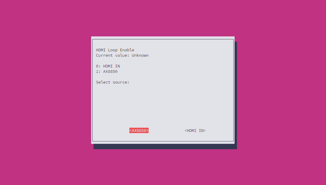
--hdmi_loop_en Switch HDMI OUT port input source between IN and AX8850
--grove_uart Set the switch on/off state for Grove UART interface
--grove_iic Set the switch on/off state for Grove I2C interface
--flash_switch Save switch configuration to flash memory (stores coil registers 4-14)
--flash_value Save value configuration to flash memory (stores holding registers 1, 2, 11, 12, 14, 16-21)
--poweroff Trigger the system power-off sequence
--lcd_brightness Get or set the LCD backlight brightness level
-P, --lcd_putc Output a character or string to the LCD display
--i2c_set_reg Write a value to an I2C device register
--i2c_get_reg Read a value from an I2C device register
--ec_button_head_event Get or set the event handler for EC head button press
--soc_button_head_event Get or set the event handler for SoC head button press
--ec_button_lcd_event Get or set the event handler for EC LCD button press
--fun_auto Get or set the automatic control mode for the proxy service
--ec_modbus_set_bit Set a specific bit in the EC Modbus coil register
--ec_modbus_get_bit Get a specific bit value from the EC Modbus coil register
--ec_modbus_input_bits Read the EC Modbus discrete input bits status
--ec_modbus_input_registers Read the EC Modbus input registers values
--ec_modbus_set_hold_registers Write values to the EC Modbus holding registers
--ec_modbus_get_hold_registers Read values from the EC Modbus holding registers
--pcie0_exists Check if a PCIe device is present in slot 0
--pcie1_exists Check if a PCIe device is present in slot 1
--V3_3_good Check if the 3.3V power rail is within normal operating range
--V1_8_good Check if the 1.8V power rail is within normal operating range
--head_button Get the current state of the head button (pressed/released)
--lcd_button Get the current state of the LCD button (pressed/released)
--version Get the EC firmware version information
-d, --data call param (string [=])
-D, --DataRaw call param raw (string [=])
-?, --help print this messageRGB LED Control
Configure the RGB LED operating mode:
ec_cli device --rgb -d 4| RGB LED Mode | Description |
|---|---|
| 0 | Controlled via rgb_set_color |
| 1 | Color gradient |
| 2 | Breathing effect |
| 3 | Flowing light effect |
| 4 | Dispersed light effect |
| 5 | Aggregated light effect |
Use the rgb_set_color command to configure the color of a single RGB LED. This command is only valid in mode 0. Note: the current interface does not support setting a range of LEDs at once. The rgb_color parameter uses a decimal RGB888 encoding (e.g. 0x00FF00 == 65280).
ec_cli device --rgb_set_color -d '{"rgb_index":0,"rgb_color": 65280}'Fan Control
Set the fan PWM duty cycle to 80%:
ec_cli device --fan -d 80{
"created": 1769747093,
"data": "ok",
"object": "",
"request_id": "",
"work_id": "fun_set_pwm"
}Read the fan speed in RPM:
ec_cli device --fanspeed{
"created": 1769753372,
"data": 9060,
"object": "",
"request_id": "",
"work_id": "get_input_registers"
}Network Information
ec_cli device --ip_eth0
ec_cli device --ip_eth1
ec_cli device --ip_wlanPD Power Information
ec_cli device --pd_power_info{
"created": 1769753175,
"data": { "voltage": "20 V", "current": "1.25 A" },
"object": "",
"request_id": "",
"work_id": "pd_info"
}Power Management
View the current device power consumption information:
ec_cli device --board{
"created": 1769756427,
"data": {
"pcie0_mv": 3352,
"pcie0_ma": 0,
"pcie1_mv": 3328,
"pcie1_ma": 0,
"usb1_mv": 5040,
"usb1_ma": 0,
"usb2_mv": 5040,
"usb2_ma": 0,
"INVDD_mv": 20112,
"INVDD_ma": 292,
"EXTVDD_mv": 20112,
"EXTVDD_ma": 28
},
"object": "",
"request_id": "",
"work_id": "board_get_power_info"
}USB Power Output
Enable USB port power output. The internal USB 3.0 #4 port is always on by default.
ec_cli device --usbds1 -d 1
ec_cli device --usbds2 -d 1
ec_cli device --usbds3 -d 1Disable USB port power output:
ec_cli device --usbds1 -d 0
ec_cli device --usbds2 -d 0
ec_cli device --usbds3 -d 0Enable enhanced USB power output. The default output capability is up to 400mA, and up to 800mA after enhancement. Currently, only USB #1 / #2 ports support power enhancement.
ec_cli device --usbds1_big -d 1
ec_cli device --usbds2_big -d 1OLED
Configure the OLED display mode:
ec_cli device --lcd -d 4| OLED Mode | Description |
|---|---|
| 0 | M5Stack characters |
| 1 | Interface voltage display, refresh every 3s |
| 2 | IP address display, refresh every 3s |
| 3 | ARM mapping |
| 4 | Text display mode, controlled via lcd_putc |
Use the lcd_putc command to print characters to the OLED screen. This command is only valid in mode 4.
ec_cli device --lcd_putc -d "Hello World!"Clear the screen by writing blank characters:
ec_cli device --lcd_putc -d " "3. Status Monitoring
Enter ec_cli echo to view status monitoring–related commands. The current version only supports reading the top button status.
root@m5stack-AI-Pyramid:~# ec_cli echo
usage: ec_cli [options] ...
options:
  -b, --button    button event
-?, --help print this messageec_cli echo --buttonPress the top button:
{ "created":1769747540,"data":{"code":0,"vale":204},"object":"","request_id":"","work_id":"buttons_thread" }
{ "created":1769747540,"data":{"code":1,"vale":204},"object":"","request_id":"","work_id":"buttons_thread" }
{ "created":1769747540,"data":{"code":0,"vale":204},"object":"","request_id":"","work_id":"buttons_thread" }
{ "created":1769747540,"data":{"code":1,"vale":204},"object":"","request_id":"","work_id":"buttons_thread" }4. Core-Config
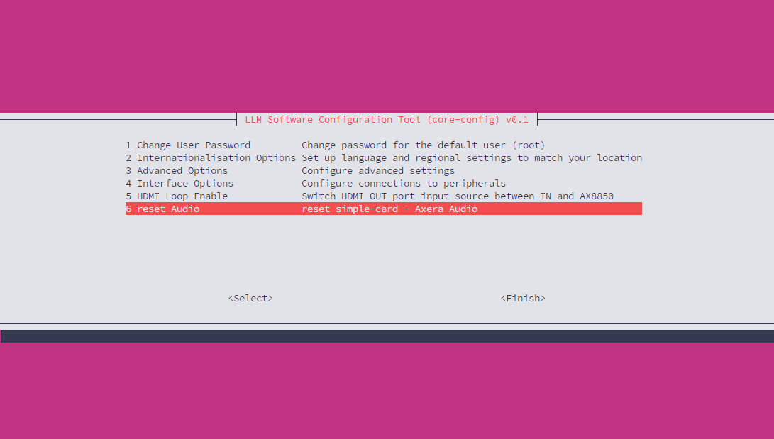
In addition to using the command line, you can also use Core-Config to open a GUI for configuration.
core-config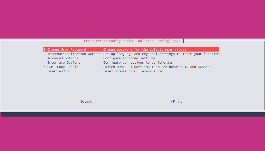
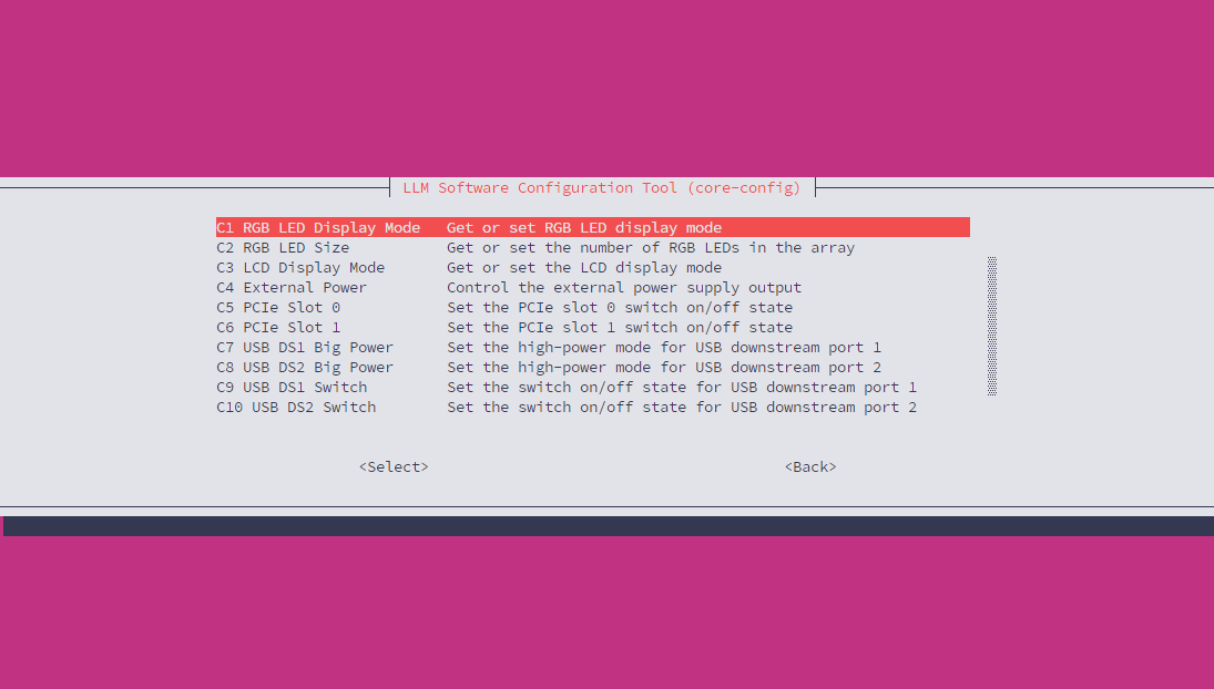
The Interface Option section contains commonly used hardware control options, such as USB power output and fan speed. The configuration options are consistent with the functionality provided by the ec_cli command-line tool.
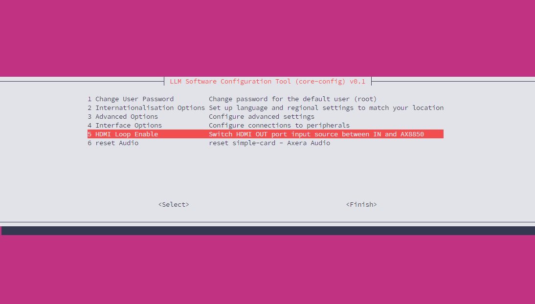
Configure Display Output
This configuration applies to AI Pyramid-Pro. It allows you to configure the Display output signal source to come from the Display Input interface or to use the AX8850 internal default output directly.
Reset Audio