

Product Guide
Linux PC
CardputerZero
AI アクセラレーターカード
LLM-8850 カード
AI & Agent
リアルタイム音声アシスタント
XiaoZhi ボイスアシスタント
AtomS3R-M12 Volcengine Kit
Industrial Control
IoT Measuring Instruments
Air Quality
PowerHub
Module13.2 PPS
VAMeter
T-Lite
Ethernet Camera
PoECAM
Wi-Fi Camera
Unit CamS3/-5MP
AI Camera
LoRa & LoRaWAN
Motor Control
ファームウェアの初期化
ディップスイッチ&ピン切り替え
VAMeter Guide
1.Functional layout
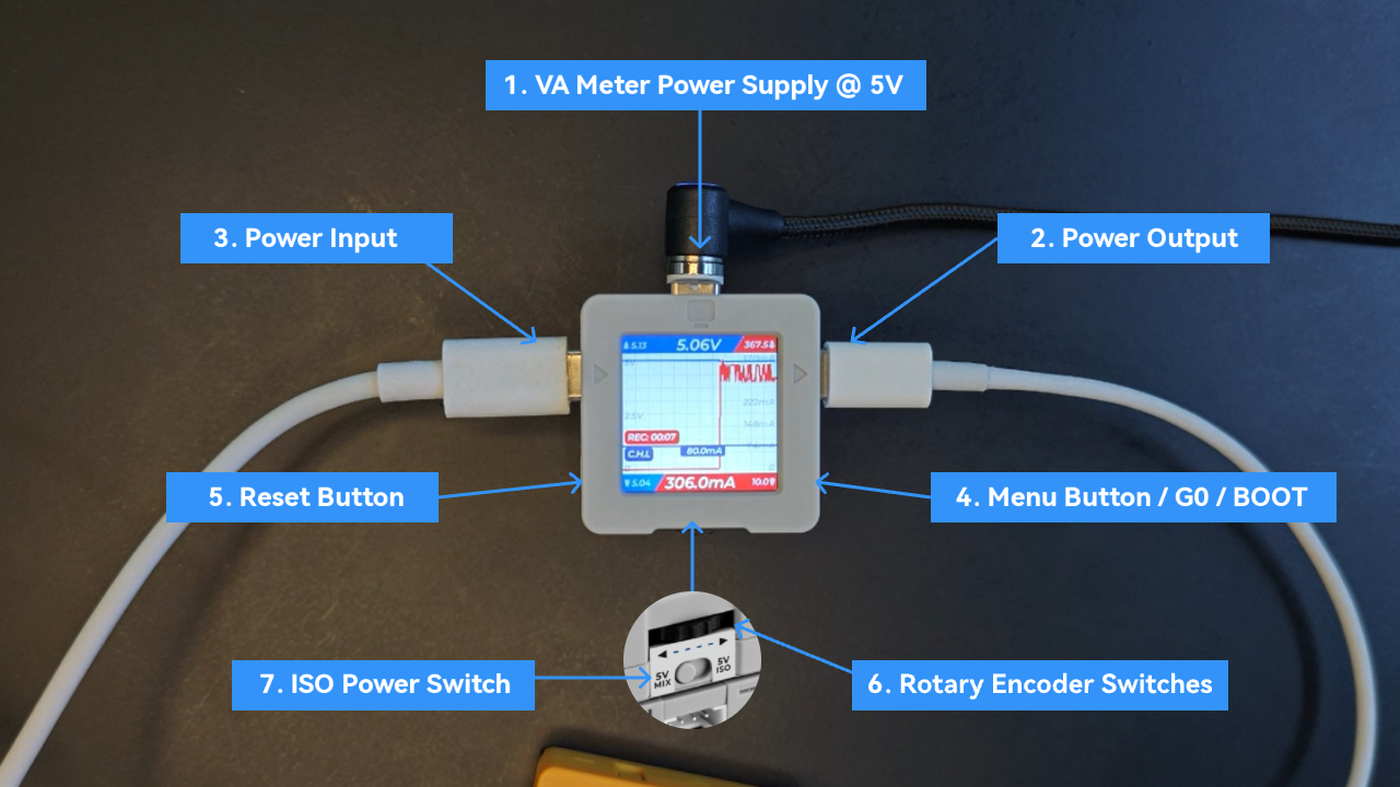
- 1.Top USB port: VAMeter device power supply, MSC mode data export, firmware burning update
- 2.Right USB port: measurement power output port
- 3.Left USB port: measurement power input port
- 4.Right button: sequentially switch menu options, long press to return to the previous level.
- 5.Left reset switch: whole machine reset
- 6.Rotary encoder switch (left, right, middle button): switch menu options left and right, middle button to confirm.
- 7.Isolation power switch
2.Power Monitor
- When VAMeter is turned on, it will enter the
Power Monitorpower consumption monitoring APP page by default. Connect the left interface to the input power. Connect the measurement load to the right interface to monitor the power consumption status in real time. Use the rotary encoder switch below to switch data pages.Press and hold the right button to return to the main menu.

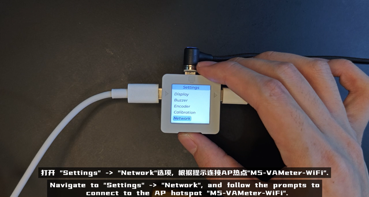
3.WiFi Configuration
1.After the device is started, switch to the settings page in the main menu, open the Network option, use your mobile phone to connect to the AP hotspot M5-VAMeter-WiFi according to the prompts, and then jump to the WiFi configuration page by scanning the QR code on the device screen or directly accessing 192.168.4.1/syscfg in the browser. Click the drop-down menu to scan and fill in the WiFi information for configuration.
2. After WiFi configuration, it will not be connected immediately, only locally saved. It will be connected in scenarios where network connection is required, such as uploading power consumption curve data to Ezdata and device firmware OTA.

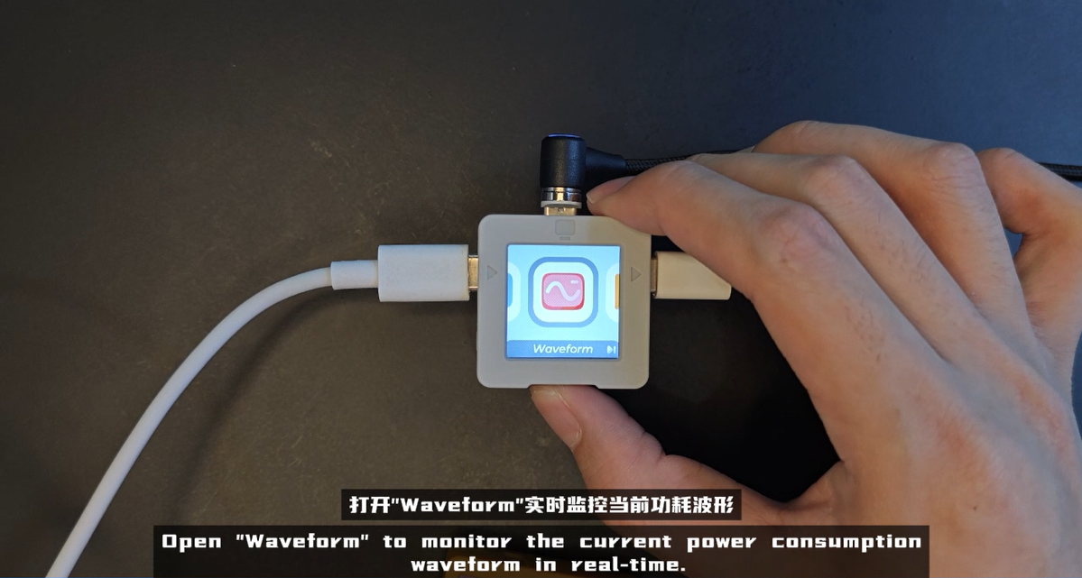
4.Waveform
1.VAMeter supports intuitively displaying the current power consumption status in the form of a curve, and also supports recording power consumption change data over a period of time, which is convenient for device power consumption analysis.
2.Usage: After the device is started, switch to the Waveform page in the main menu by pressing the button. At this time, you can see the real-time power consumption curve monitoring. At this time, click the middle button of the rotary encoder switch to record. After the recording is completed, the data will be automatically saved and can be used for local preview analysis.

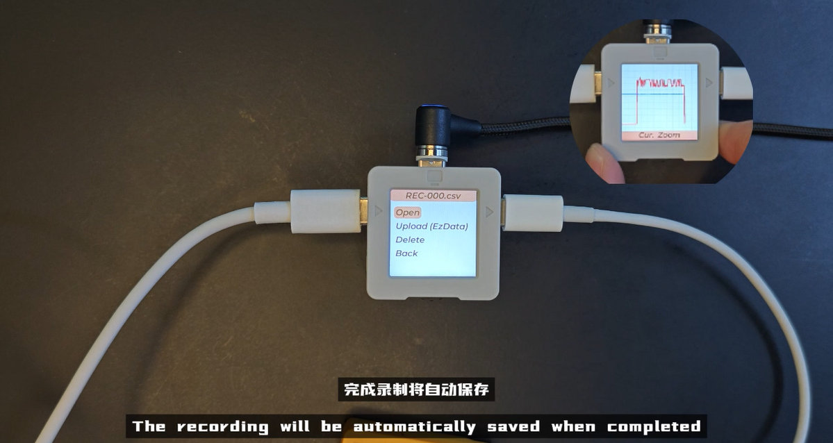
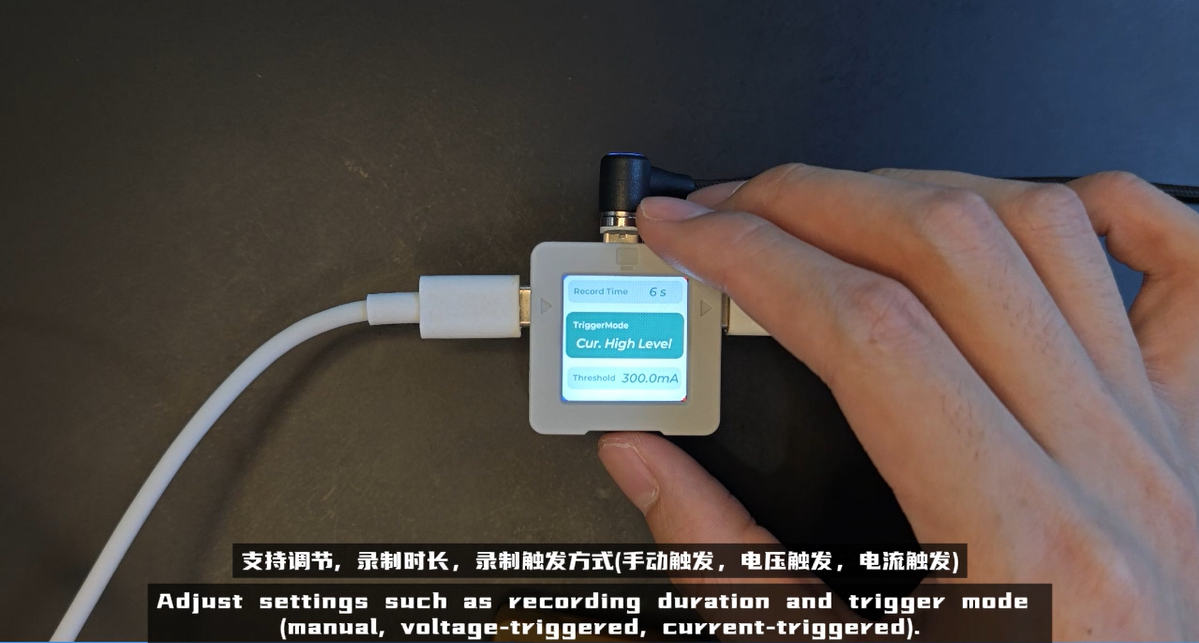
The configuration and recording process is: click the right button to enter the configuration page -> Rotate the encoder switch to switch configuration options, click the middle button again to select/confirm the configuration (supports the selection of three trigger modes:
manual button trigger, current trigger, and voltage trigger. The latter two require a trigger threshold to be configured. The current version supports a maximum recording time of 10min) -> Click the right button to complete the configuration -> Click the middle button of the rotary encoder switch to start recording.Manual button trigger:
Press the middle button of the rotary encoder switchtodirectlystart data recording`Current trigger: After configuring the current trigger mode and the corresponding threshold,
Press the middle button of the rotary encoder switch, the device will enter thewaiting state, and whengreater than/less than the current trigger threshold, the datarecordingwill be triggered.Voltage trigger: After configuring the voltage trigger mode and the corresponding threshold,
Press the middle button of the rotary encoder switch, the device will enter thewaiting state, and whengreater than/less than the voltage trigger threshold, the value will trigger datarecording.
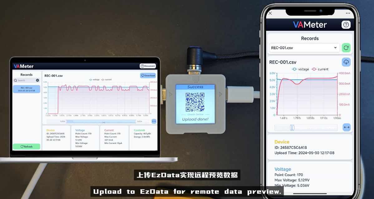
Upload Ezdata, the device will use the configured WiFi information to connect to the Internet, and send data to the Ezdata server, and the remote interface QR code will be displayed on the screen. Note: WiFi configuration must be completed before using this function.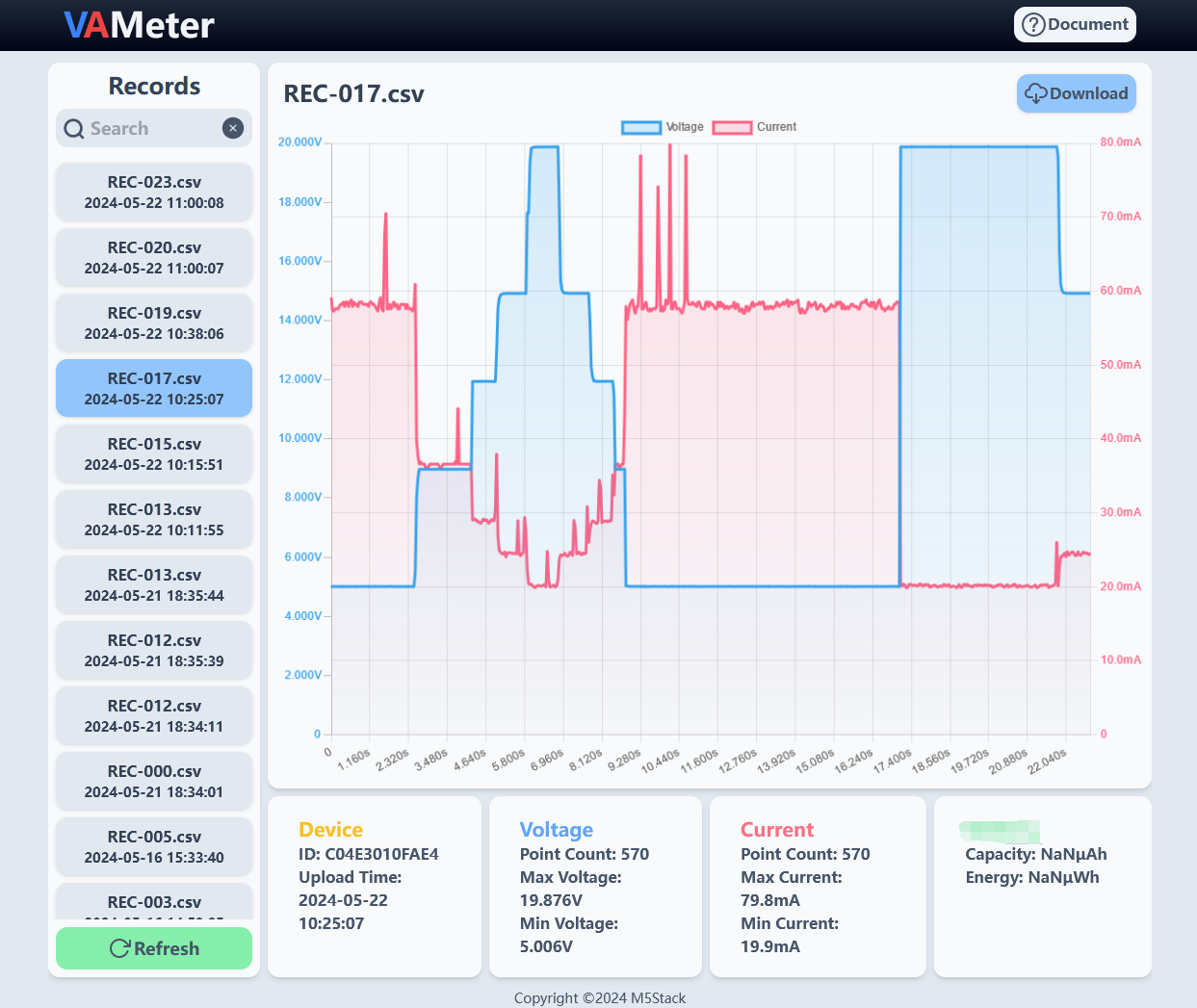
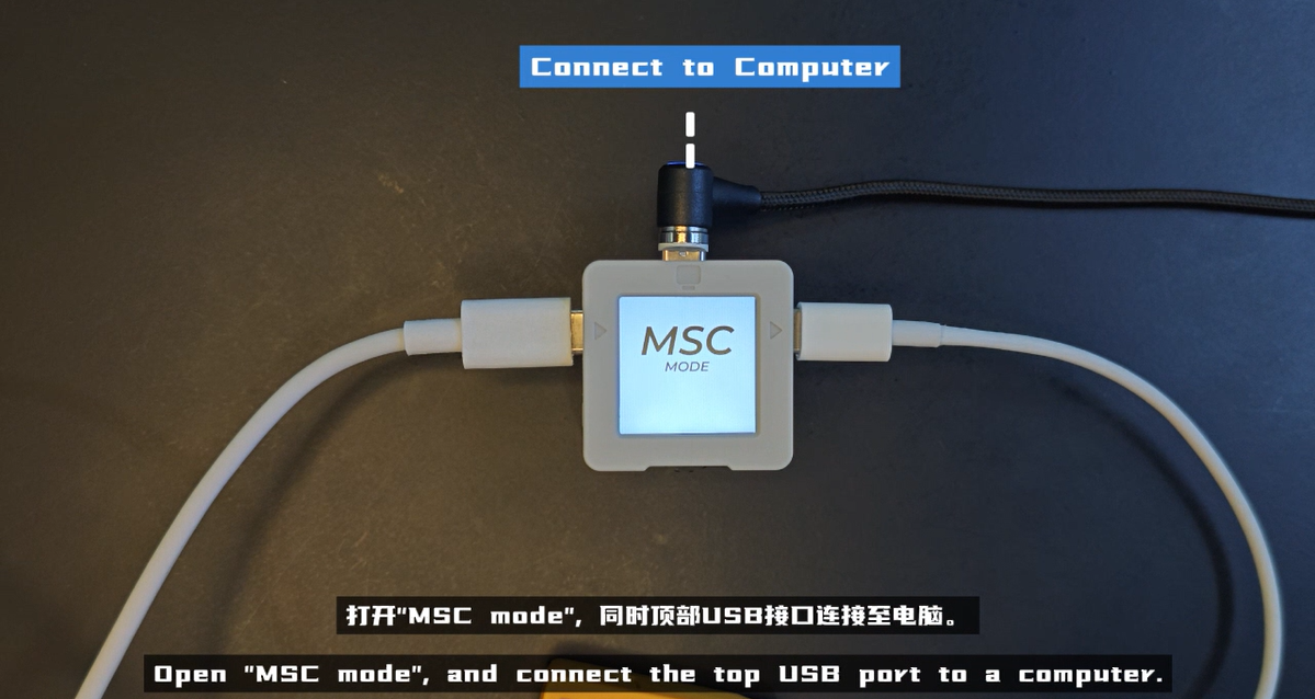
5.Export CSV and modify the startup logo
1.Connect the USB port on the top of VAMeter to the computer. After the device starts, switch to the settings page in the main menu, open the Files option, and enter MSC mode. At this time, the computer will recognize the storage device.
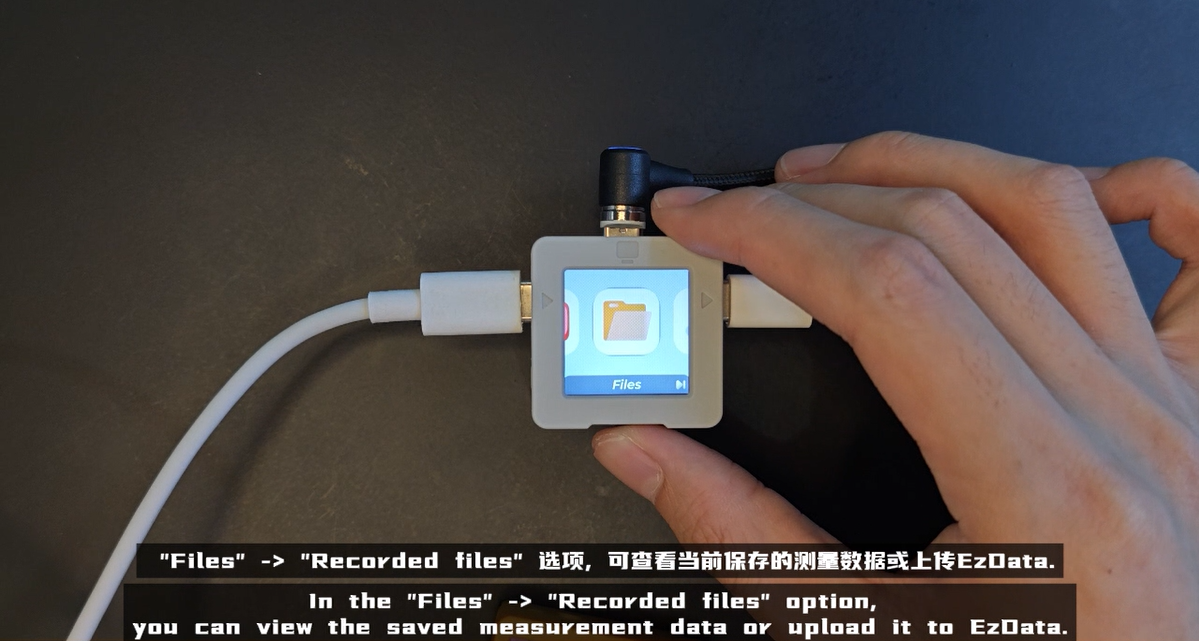

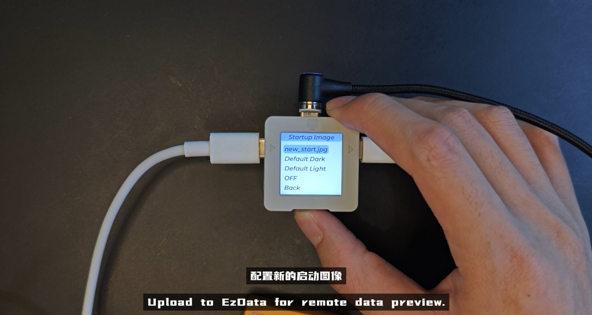
rec under the storage device to obtain all saved measurement data sets.startup_logo under the storage device and add a new startup image. Currently only jpg format files are supported, and the recommended resolution is 240x240. After saving, VAMeter returns to the main menu and enters the Settings->Startup Image option to configure a new startup image.
6.Firmware OTA
1.After the device is started, switch to the settings page from the main menu, turn on the OTA Upgrade option, and press the middle button of the rotary encoder switch in sequence according to the prompts to upgrade the firmware. Note: WiFi configuration must be completed before using this function.
7.VAMeter Base
1.The VAMeter set comes with a standard VAMeter Base, which has a built-in mechanical relay. The base interface supports a DC 5-24V power input, which can be used for load power supply and overall system power supply. Based on this peripheral, users can apply it to some automated testing scenarios while being able to monitor the input power in real-time. Additionally, it provides a HY2.0-4P expansion interface, allowing for more possibilities through secondary development. The relay can be tested by selecting the Settings -> Base Test option.
