

Product Guide
Linux PC
CardputerZero
AI Accelerator Card
LLM-8850 Card
Large Language Models
AI & Agent
Real-Time AI Voice Assistant
XiaoZhi Voice Assistant
AtomS3R-M12 Volcengine Kit
Offline Voice Recognition
Industrial Control
IoT Measuring Instruments
Air Quality
PowerHub
Module13.2 PPS
VAMeter
T-Lite
Input & Output Devices
Ethernet Camera
PoECAM
Wi-Fi Camera
Unit CamS3/-5MP
AI Camera
LoRa & LoRaWAN
Motor Control
Restore Factory Firmware
DIP Switch Usage Guide
Module GPS v2.0 DIP Switch Instruction Manual
1. Function Overview
To avoid issues caused by pin conflicts when stacking the Module GPS v2.0 with the host, the module adopts DIP switches to flexibly switch the connections of key pins. Users can adjust the corresponding pin configuration based on the host used (such as Core/Basics, Core2, or CoreS3) to ensure stable system operation.

2. DIP Switch Position and Pin Mapping
2.1 DIP Switch Position
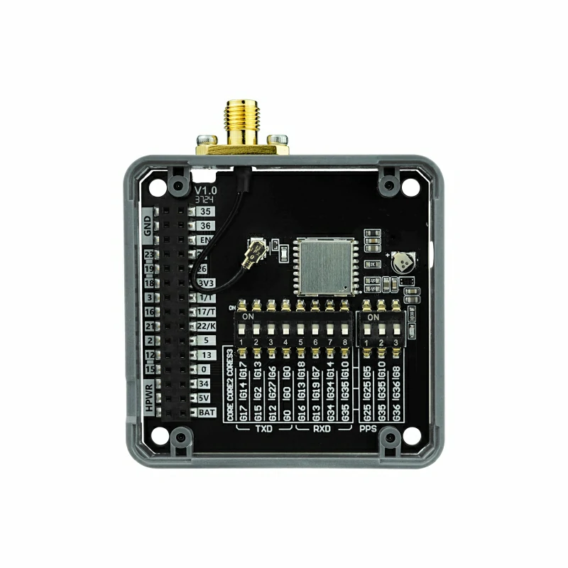
The DIP switches are located at a designated position on the module, as shown in the following images:
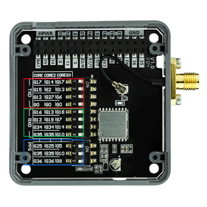
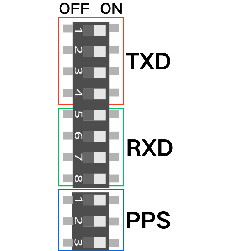
As shown in the images above, the DIP switches are used to switch the four functional pins: TXD, RXD, PPS
2.2 Pin Mapping Table
For different hosts, the selectable mappings for the key pins are as follows:
| CORE | CORE2 | CORES3 | |
|---|---|---|---|
| TXD | G17 | G14 | G17 |
| G15 | G2 | G13 | |
| G12 | G27 | G6 | |
| G0 | G0 | G0 | |
| RXD | G16 | G13 | G18 |
| G13 | G19 | G7 | |
| G34 | G34 | G14 | |
| G35 | G35 | G10 | |
| PPS | G25 | G25 | G5 |
| G35 | G35 | G10 | |
| G36 | G36 | G8 |
Note:
- TXD, RXD, PPS can all be selected via the DIP switch to choose the specific connected pin. For example, on a Core (Basic) host:
- TXD: can be selected as G17, G15, G12, or G0 (four options)
- RXD: can be selected as G16, G13, G34, or G35 (four options)
- PPS: can be selected as G25, G35, or G36 (three options)
3. DIP Switch Configuration Operation
Please follow the steps below to adjust the DIP switch configuration:
Power Down Operation
Before adjusting the DIP switches, please ensure that the module is completely powered off to avoid damaging the hardware.Set the DIP Switch
Select the corresponding pin mapping according to the host being used.
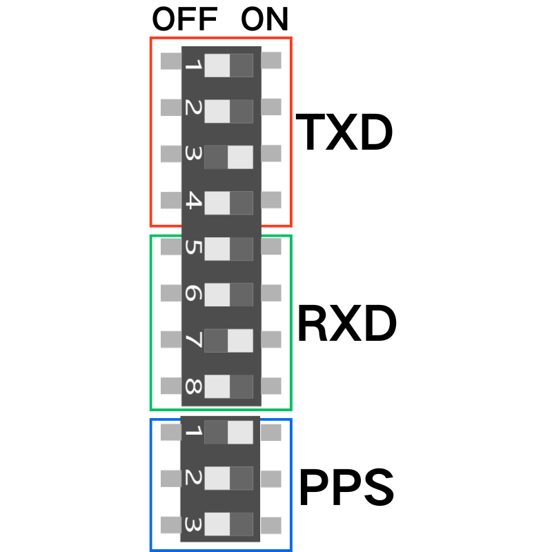
In the diagram above, the DIP switch positions are chosen as:
TXD → G12
RXD → G34
PPS → G25
- Reconnect and Power On
After completing the DIP switch settings, reconnect the module and apply power for further use.