

Product Guide
Linux PC
CardputerZero
AI Accelerator Card
LLM-8850 Card
Large Language Models
AI & Agent
Real-Time AI Voice Assistant
XiaoZhi Voice Assistant
AtomS3R-M12 Volcengine Kit
Offline Voice Recognition
Industrial Control
IoT Measuring Instruments
Air Quality
PowerHub
Module13.2 PPS
VAMeter
T-Lite
Input & Output Devices
Ethernet Camera
PoECAM
Wi-Fi Camera
Unit CamS3/-5MP
AI Camera
LoRa & LoRaWAN
Motor Control
Restore Factory Firmware
DIP Switch Usage Guide
Module GNSS DIP Switch Explanation Document
1. Overview
To avoid pin conflicts when Module GNSS is stacked with the main unit, the module uses a DIP switch to flexibly switch the connection of key pins. Users can adjust the corresponding pin configuration based on the host they are using (such as Core/Basic, Core2, or CoreS3) to ensure stable system operation.

2. DIP Switch Position and Pin Mapping
2.1 DIP Switch Position
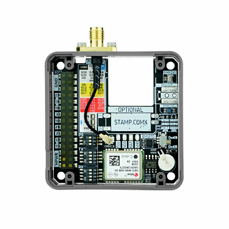
The DIP switch is located at the specified position on the module, as shown in the diagram below:
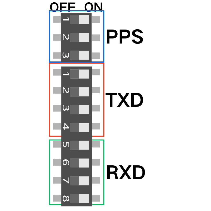
As shown in the diagram, the DIP switch is used to switch three functional pins: TXD, RXD, PPS
2.2 Pin Mapping Table
The pin mapping options for different hosts are as follows:
| CORE | CORE2 | CORES3 | |
|---|---|---|---|
| PPS | G34 | G34 | G14 |
| G35 | G35 | G10 | |
| G0 | G0 | G0 | |
| TXD | G0 | G0 | G0 |
| G12 | G27 | G6 | |
| G15 | G2 | G13 | |
| G17 | G14 | G17 | |
| RXD | G35 | G35 | G10 |
| G34 | G34 | G14 | |
| G13 | G19 | G7 | |
| G16 | G13 | G18 |
Note:
- TXD, RXD, PPS can be selected through the DIP switch to choose the specific pin to connect. For example, on Core (Basic) host:
- PPS: Choose from G34, G35, or G0 (one of the three)
- TXD: Choose from G0, G12, G15, or G17 (one of the four)
- RXD: Choose from G35, G34, G13, or G16 (one of the four)
3. DIP Switch Switching Operation
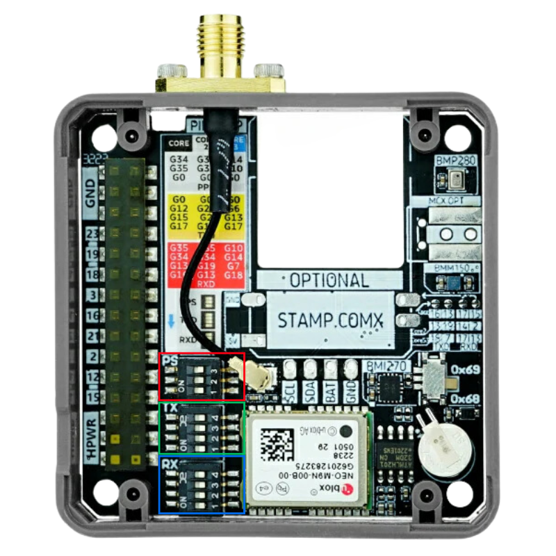
Please follow the steps below to adjust the DIP switch configuration:
Power Off
Before adjusting the DIP switch, make sure the module is completely powered off to avoid hardware damage.Set the DIP Switch
Select the corresponding pin mapping according to the host you are using.
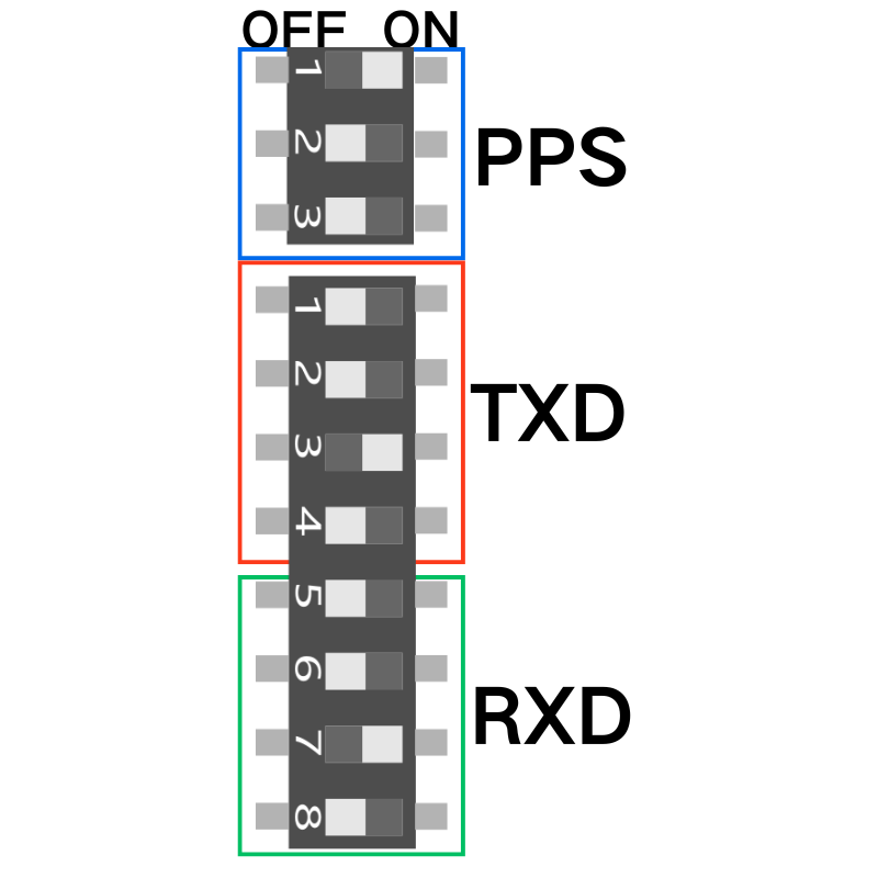
As shown in the image, the DIP switch is set as follows: ( Core (Basic) + Module GNSS )
PPS → G34
TXD → G34
RXD → G25
- Rewire and Power On
After setting the DIP switch, reconnect the module and power it on for subsequent use.