CoreMP135 Overlay Device Trees support
M5_CoreMP135_debian12_20240515, M5_CoreMP135_buildroot_20240515 and above (enable CONFIG_OF_OVERLAY support)1.Device tree plug-in format
1.The device tree plug-in is an addition based on the device tree. The syntax is exactly the same as the device tree. You can copy the previously written device tree nodes into the device tree plug-in. The device tree plug-in has a relatively fixed format. It can even be considered that it just adds a "shell" to the device node and the kernel can dynamically load it after compilation. The format is as follows, specific nodes are omitted.
/dts-v1/;
/plugin/;

  /{
         fragment@0 {
             target-path = "/";
             __overlay__ {
                 /*Add the node to be inserted here*/
                 .......
             };
         };

         fragment@1 {
             target = <&XXXXX>;
             __overlay__ {
                 /*Add the node to be inserted here*/
                 .......
             };
         };
     .......
};- Line 1: Used to specify the version of dts.
- Line 2: Indicates that undefined references are allowed and recorded. The device tree plug-in can reference nodes in the main device tree, and these "referenced nodes" are undefined for the device tree plug-in, so the device tree Plugins should be added with "/plugin/".
- Line 6: Specify the loading location of the device tree plug-in. By default, we load it under the root node, which is target-path = "/", or use target = <&XXXXX> to add nodes or attributes to a certain node.
- Lines 7-8: The device and node we want to insert or the device tree node we want to reference (append) are placed in overlay {...}. You can add, modify or overwrite the nodes of the main device tree.
Another device tree plug-in format: The writing method of this plug-in is the same as the formal dts format. The only difference is that the second line declares that this plug-in is applied in the form of a plug-in.
/dts-v1/;
/plugin/;

&{/} {
     /*Here, under the root node "/", add the node or attribute to be inserted*/
};

&XXXXX {
     /*Here, under the node "XXXXX", add the node or attribute to be inserted*/
};2. Device tree plug-in case
1.Taking the CoreMP135 device as an example, write a device tree plug-in led-overlay.dts that inserts the LED device node.
// file: led-overlay.dts
/dts-v1/;
/plugin/;

/{
     fragment@0 {
         target-path = "/";
         __overlay__ {
             leds {
                 compatible = "gpio-leds";

                 led-blue {
                     function = "heartbeat"; // LED_FUNCTION_HEARTBEAT
                     color = <3>; // LED_COLOR_ID_BLUE
                     gpios = <&gpioc 13 1>; // &gpioc 13 GPIO_ACTIVE_LOW
                     linux,default-trigger = "heartbeat";
                     default-state = "off";
                 };
             };
         };
     };
};2.Use the dtc tool to compile the device tree
dtc -I dts -O dtb -o led-overlay.dtbo led-overlay.dts

ls
led-overlay.dtbo led-overlay.dts3.Use of DTBO in uboot
1.The boot file stored in the /boot directory of the CoreMP135 root file system, where /boot/extlinux/extlinux.conf is the boot script of uboot. Through this script, you can set the device tree to be overlaid on startup.
label stm32mp135f-core135-buildroot
kernel/boot/zImage
devicetree /boot/stm32mp135f-core135.dtb
append root=/dev/mmcblk0p5 rw panic=5 quiet rootwait- label: startup label, there can be multiple startup labels, uboot can select according to the startup label when booting.
- kernel: the kernel file to be started
- devicetree: To start the kernel device tree
- append: added kernel startup parameters
- For more parameters, please refer to the pxe menu of uboot.
2.What we need to pay attention to is the fdtoverlays parameter, which is used to define the dtbo device tree file that enables overlay. The specific operations are as follows:
# Compile the dtbo device tree file and transfer it to CoreMP135 (Note: The default root user may not have ssh permissions enabled. Please modify the configuration or create a new user for transfer)
scp led-overlay.dtbo root@192.168.2.52:/root
# Place the device tree file in the /boot boot directory.
cp /root/led-overlay.dtbo /boot3.Set the dtbo parameter in the boot file /boot/extlinux/extlinux.conf
label stm32mp135f-core135-buildroot
kernel/boot/zImage
devicetree /boot/stm32mp135f-core135.dtb
fdtoverlays /boot/led-overlay.dtbo
append root=/dev/mmcblk0p5 rw panic=5 quiet rootwait4.Restart the device and we can see the led device we added in the /sys/class/leds directory.
4.Usage of DTBO in Linux
1.Linux can also dynamically adjust the device tree during runtime. This method relies on the support of the dtbocfg.ko module. The relevant precautions are as follows.
CONFIG_OF_OVERLAY is turned on when compiling the kernel. 2. Download and cross-compile the https://github.com/m5stack/dtbocfg kernel project to generate the
dtbocfg.ko kernel module. 3. Load
dtbocfg.ko in the system2.Kernel compilation must be completed before cross-compiling the module. The module generates ko files through external compilation. (Please replace $PROJECT_PATH with the actual project path)
git clone https://github.com/m5stack/dtbocfg.git
cddtbocfg

make ARCH=arm KERNEL_SRC=$PROJECT_PATH/Core135_buildroot/output/build/linux-custom CROSS_COMPILE=$PROJECT_PATH/Core135_buildroot/output/host/bin/arm-buildroot-linux-gnueabihf- -j163.Place the generated dtbocfg.ko in the path /lib/modules/$version/kernel/drivers/, run depmod -a to update the driver dependencies, and then load the module through the modprobe command.
depmod -a
#Load dtbocfg module
modprobe dtbocfg4.Copy the previously compiled led-overlay.dtbo to the system and import it according to the following process.
# Mount the configs file system. If the system does not automatically mount the directory, you need to mount it manually.
# mount -t configfs none /sys/kernel/config

#Create loading directory
mkdir /sys/kernel/config/device-tree/overlays/leds

# After the creation is completed, two files dtbo, status will be automatically generated in the directory.
ls /sys/kernel/config/device-tree/overlays/leds
dtbo status

# Fill dtbo
cat led-overlay.dtbo > /sys/kernel/config/device-tree/overlays/leds/dtbo

# Start dtbo
echo 1 > /sys/kernel/config/device-tree/overlays/leds/statusAfter completing the above steps, the current device tree plug-in has been successfully imported and taken effect.
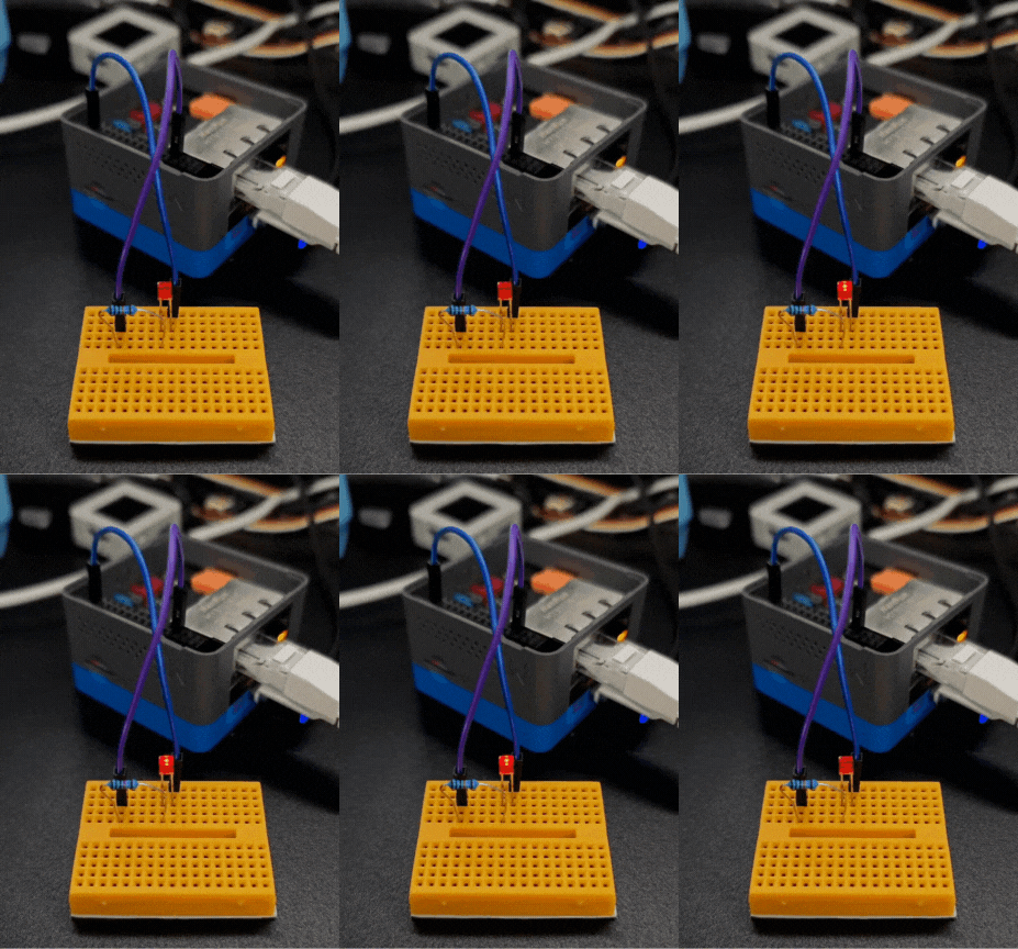
5.Check the PC13 pin status through an oscilloscope or build a simple LED circuit through a breadboard to check the implementation effect.

