

Product Guide
Linux PC
CardputerZero
AI Accelerator Card
LLM-8850 Card
Large Language Models
AI & Agent
Real-Time AI Voice Assistant
XiaoZhi Voice Assistant
AtomS3R-M12 Volcengine Kit
Offline Voice Recognition
Industrial Control
IoT Measuring Instruments
Air Quality
PowerHub
Module13.2 PPS
VAMeter
T-Lite
Input & Output Devices
Ethernet Camera
PoECAM
Wi-Fi Camera
Unit CamS3/-5MP
AI Camera
LoRa & LoRaWAN
Motor Control
Restore Factory Firmware
DIP Switch Usage Guide
StamPLC Usage Tutorial
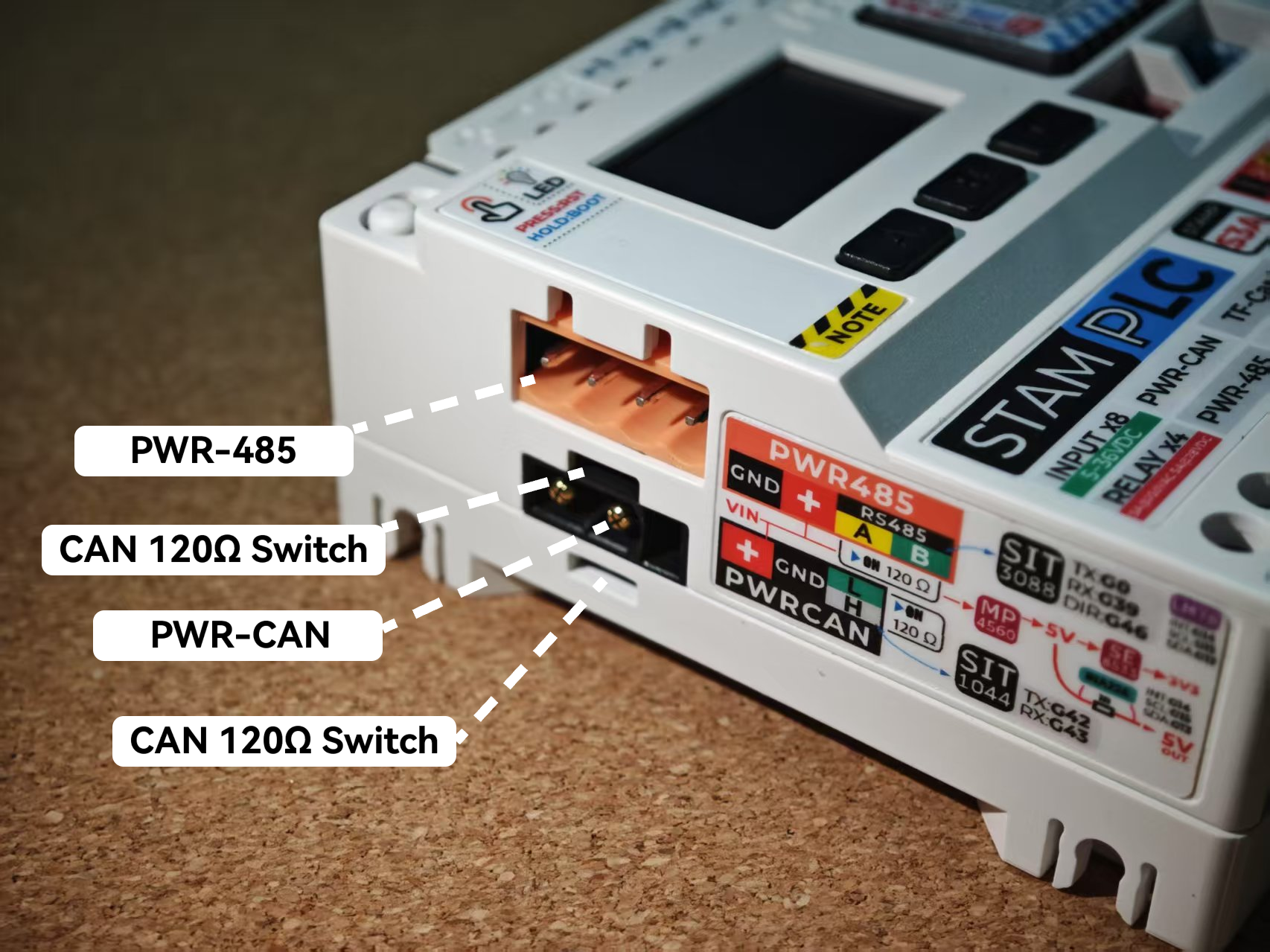
1. Function Layout
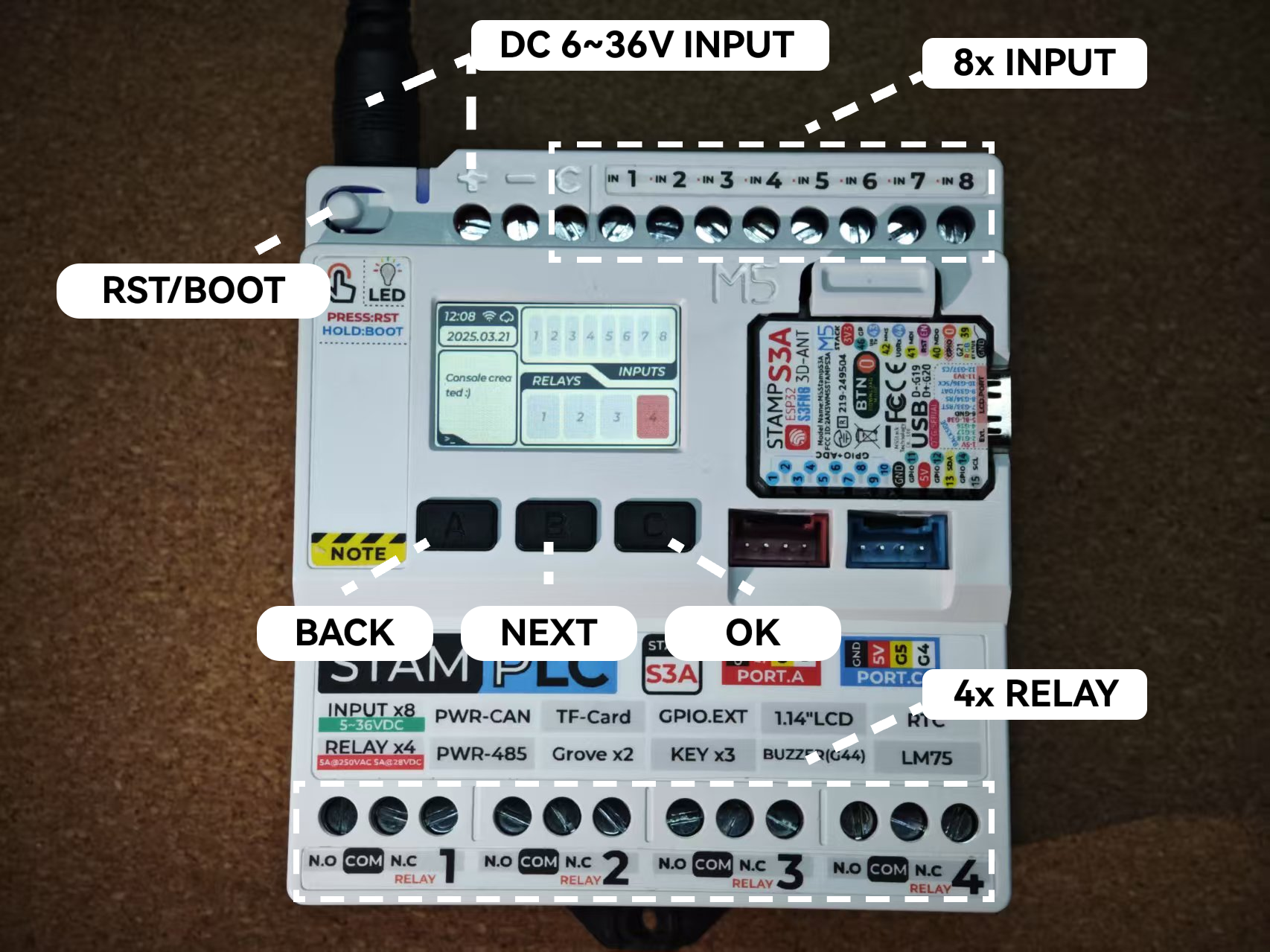
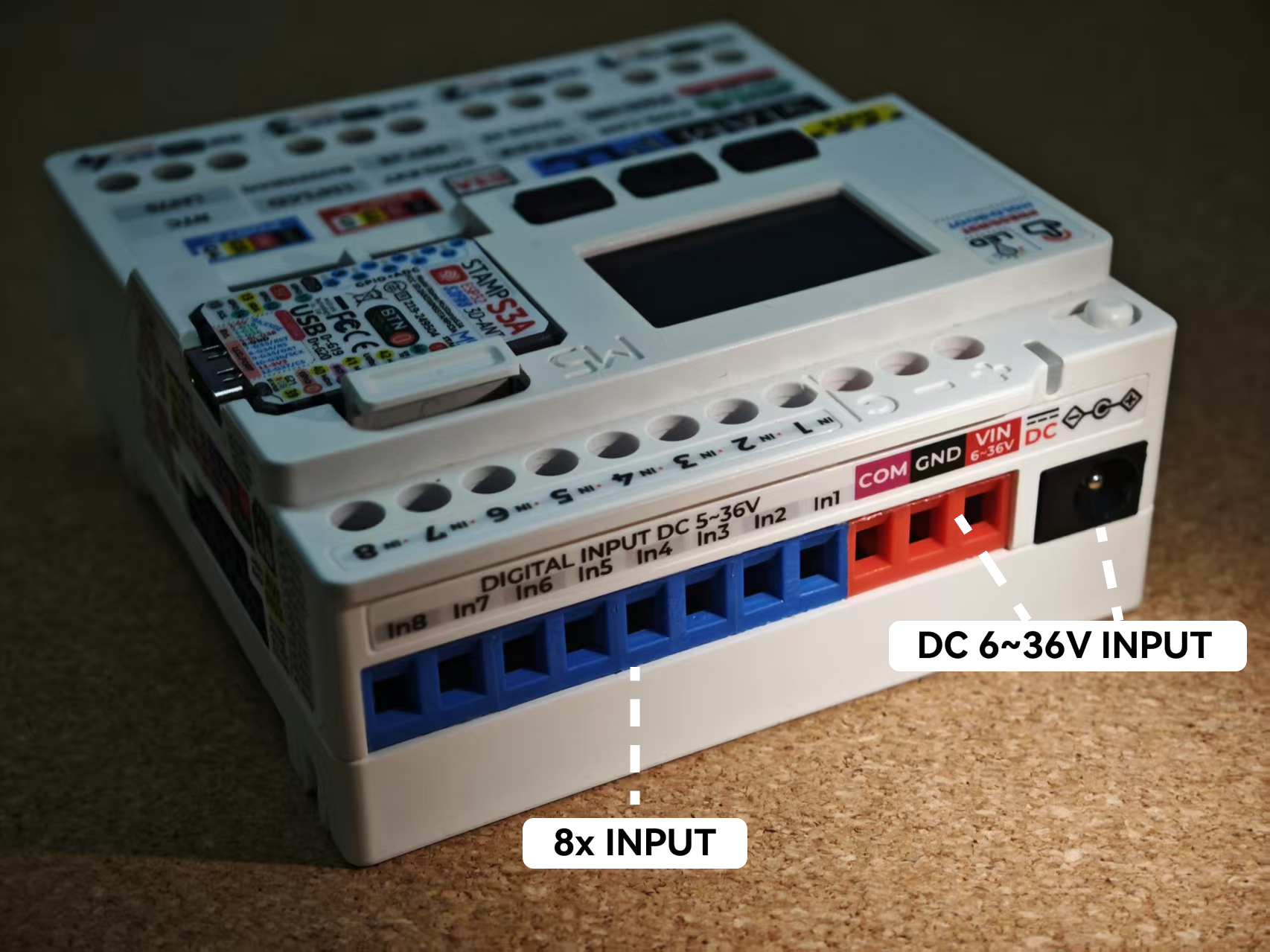
- Power Supply: DC 6 ~ 36V @ 1A
- RST Button: Single press to reset; long press (red light on) to enter download mode
- Button A: BACK, return to the previous level
- Button B: NEXT, switch to the next item
- Button C: OK, confirm selection
- INPUT: 8x isolated inputs
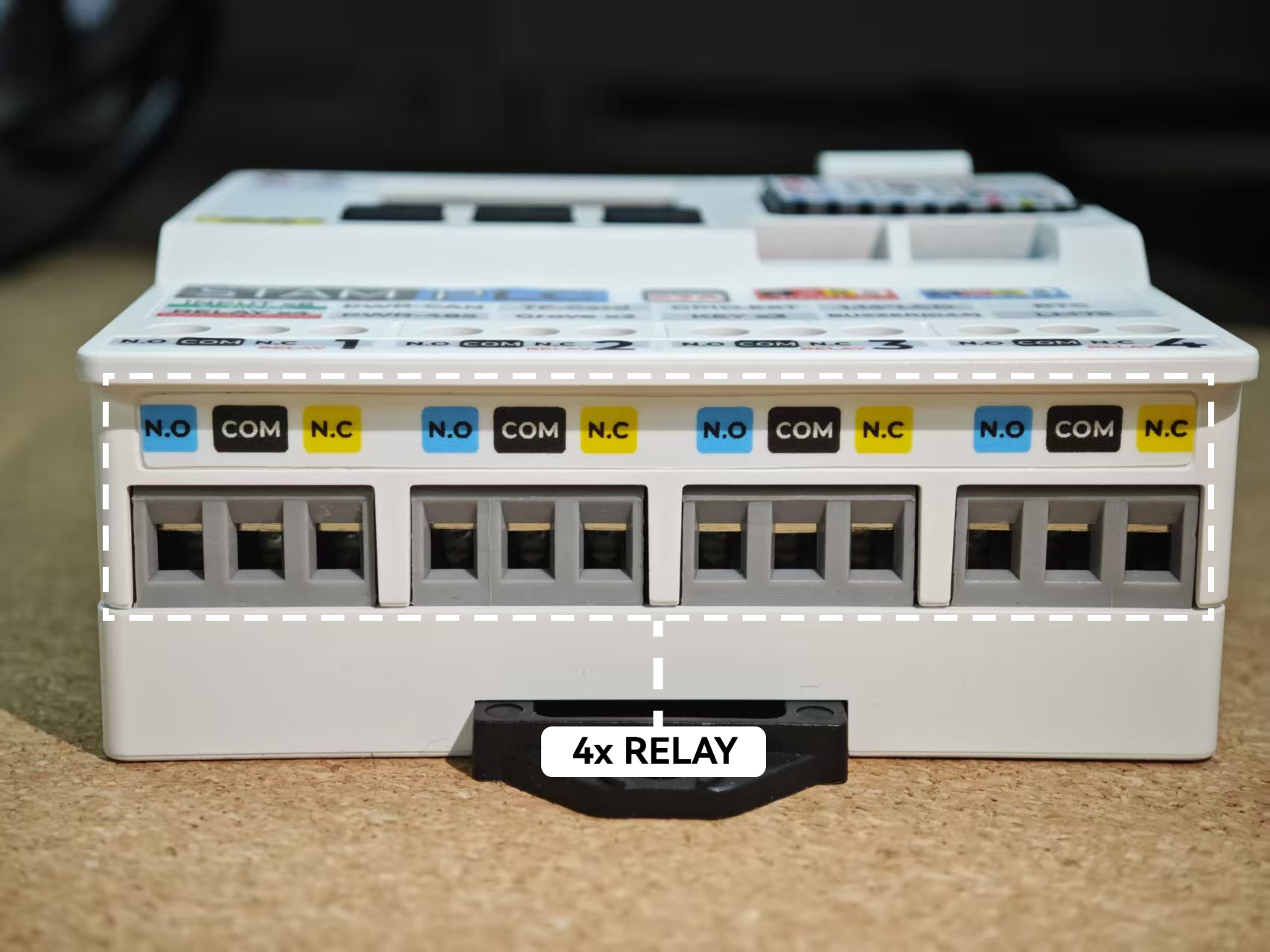
- RELAY: 4x relay control
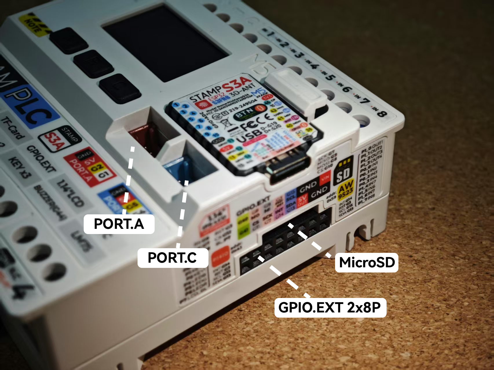
- PORT.A/PORT.B: Grove expansion interfaces
- GPIO.EXT: 2x8P bus expansion
- microSD Card Slot
- PWR-CAN: PWR-CAN 120Ω termination resistor connection switch
- PWR-485: PWR-485 120Ω termination resistor connection switch
2. Dashboard
The Dashboard displays the status of the relays and input channels in real time. The left-side log monitor shows operation records, and the navigation bar displays the current network and Ezdata service connection status.


3. Ezdata
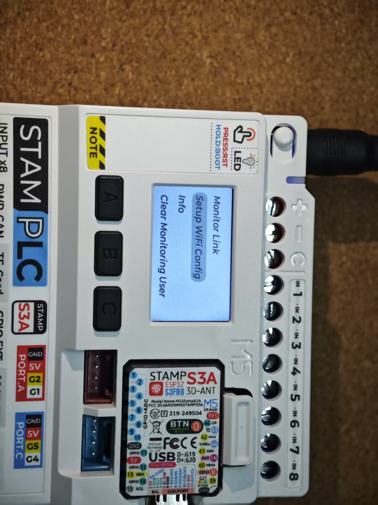
The default StamPLC firmware supports Ezdata connectivity, enabling remote relay control and input status monitoring. Use Button A to return to the main menu, then press Button B to navigate to the Ezdata option. Press Button C to confirm and enter the Ezdata configuration page. Then press Button B again to switch to the WIFI configuration option and confirm.

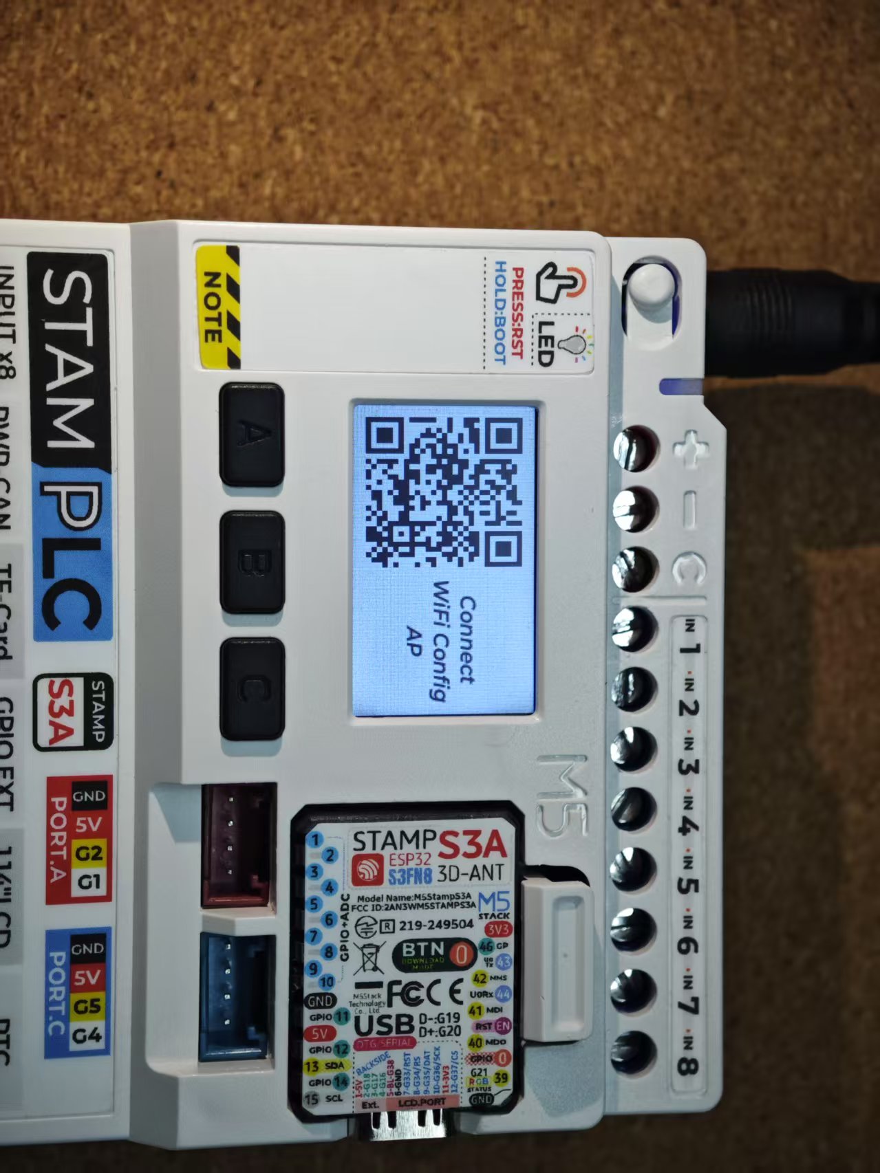
At this point, the device enters network configuration mode. Use your mobile phone to scan the QR code on the screen or manually connect to the AP hotspot M5StamPLC-WiFi-Config, then use a browser (Chrome is recommended) to directly access 192.168.4.1, which will redirect you to the WiFi configuration page. Click the drop-down menu to scan and fill in your WiFi information for configuration.
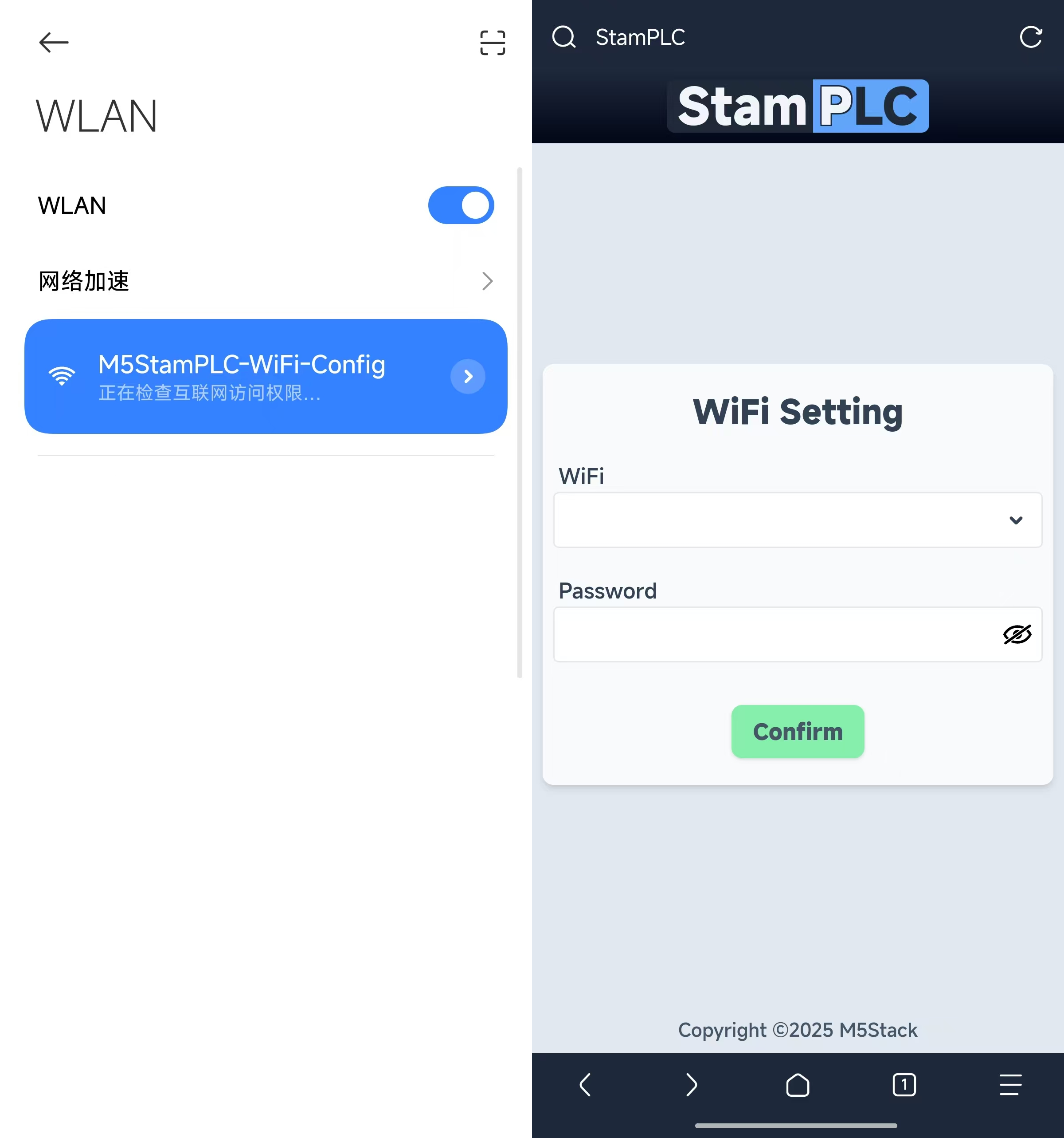
- Only supports connection to 2.4G WiFi.
- After WiFi configuration, the device will automatically attempt to connect in the background, and once the network connection is successful, the Ezdata service connection will be automatically enabled. The connection status can be viewed in the navigation bar on the Dashboard page.
Select the Monitor Link option to view the QR code for the remote access page. Use your phone to scan and access the remote page, then log in with your M5Stack account to enter the control panel.
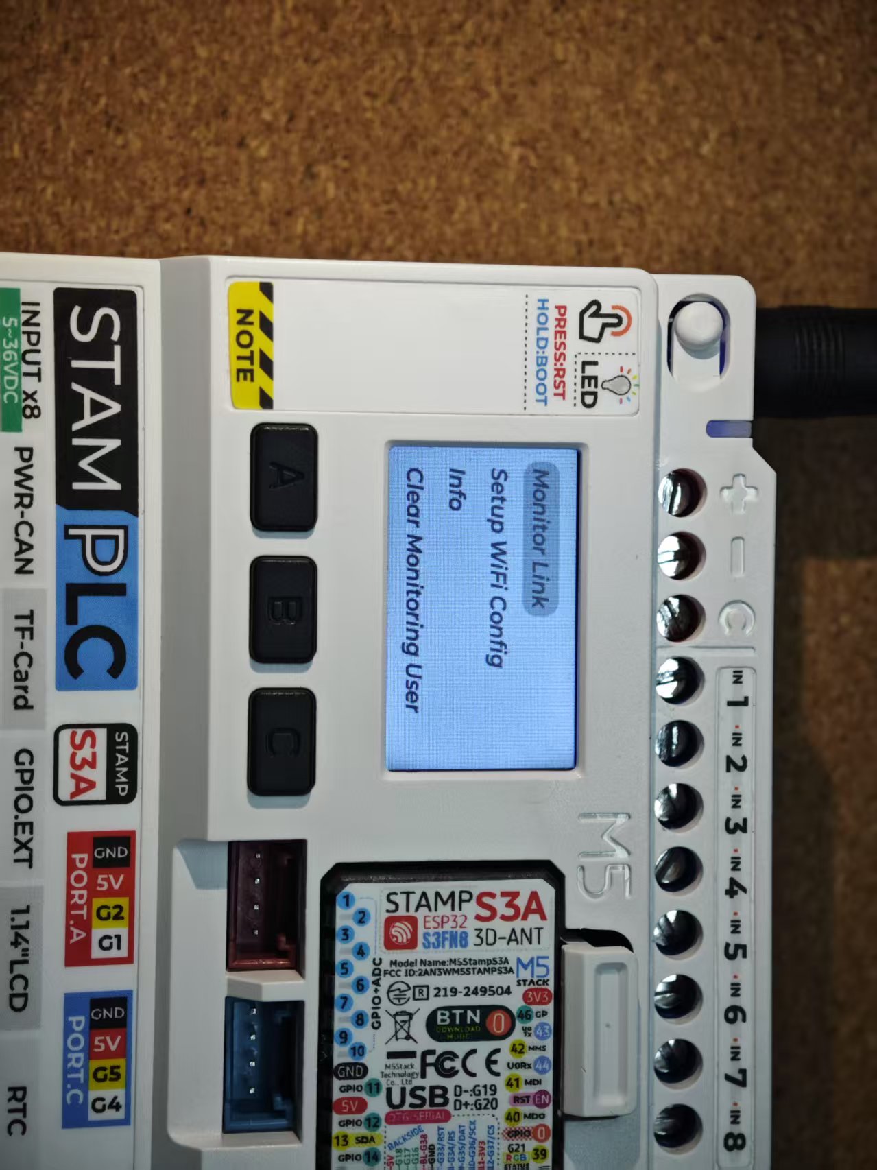


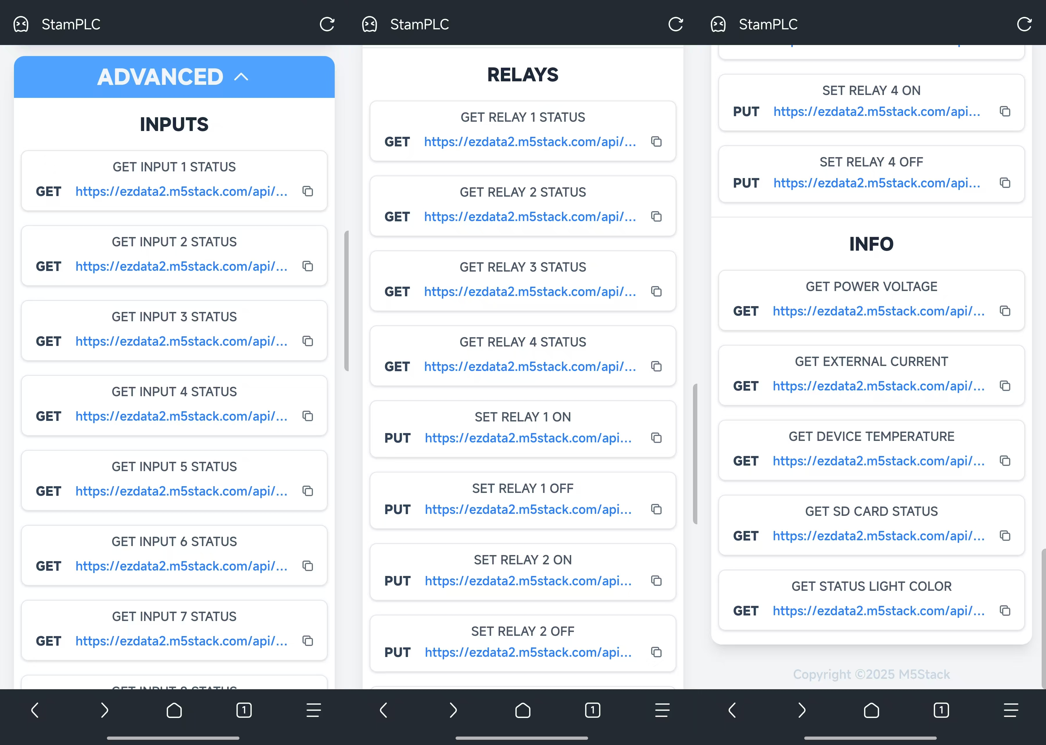
To facilitate remote interactive control of StamPLC via other devices, the Ezdata service also provides an HTTP API for remote control of StamPLC. Click the ADVANCED option at the bottom of the page to view and copy the corresponding URL, then use the specified request method for control.
The same StamPLC device allows multiple users to use it concurrently. When accessing the control panel page via the device's Monitor Link QR code and logging in, the logged-in user will be added to the current StamPLC's authorized user list. Users who have already been added can log in and use the device directly through the device's device_id URL.
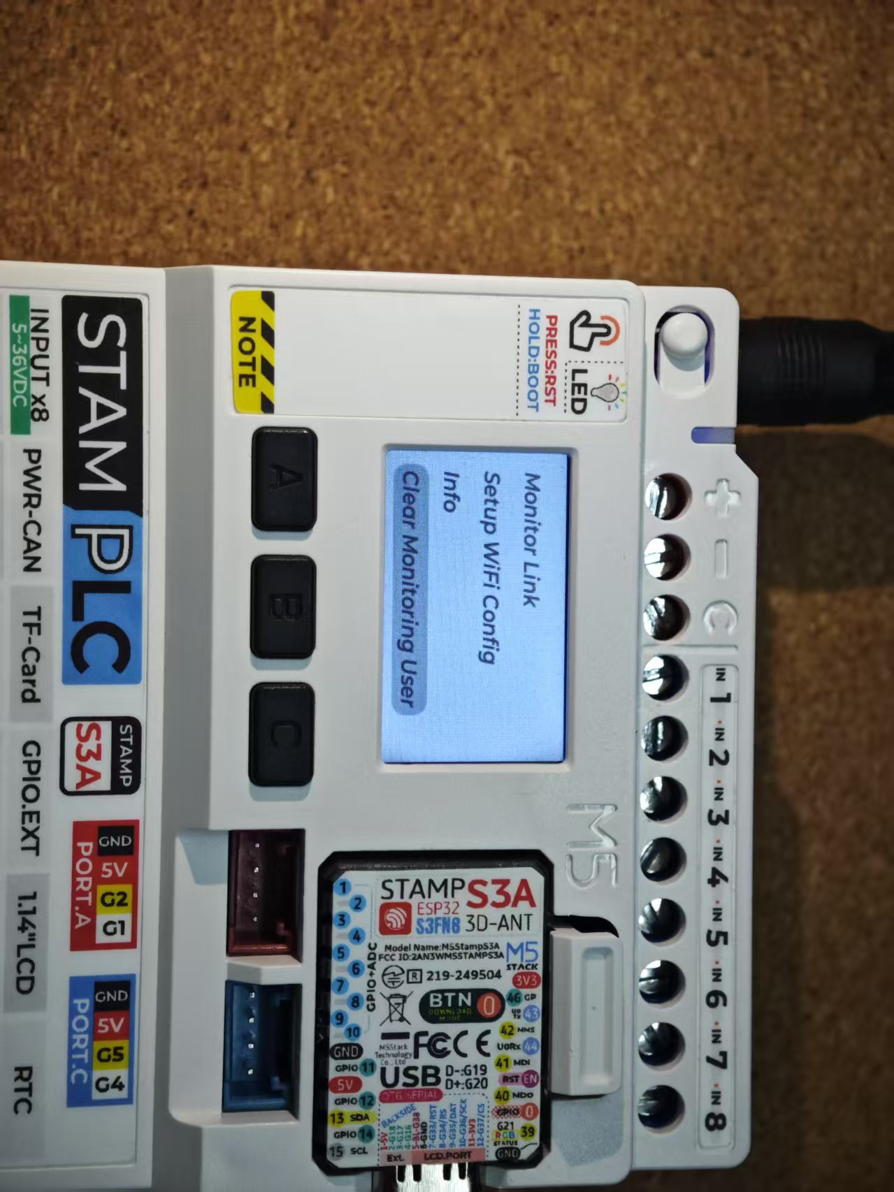
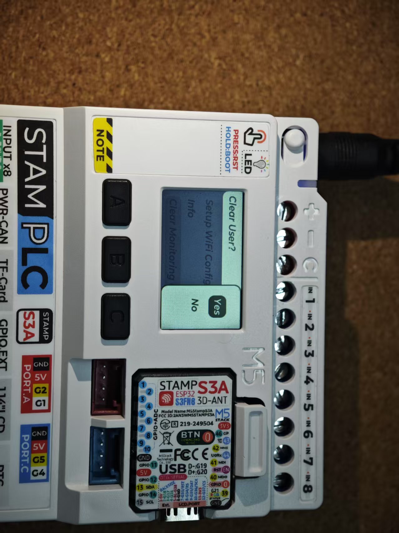
- device_id URL
https://ezdata-stamplc.m5stack.com/${device_id}The Ezdata function menu provides a Clear Monitoring option to clear all authorized users, thereby restricting access by other users. (This step will refresh all HTTP API tokens, and URLs based on the old tokens will become invalid.)
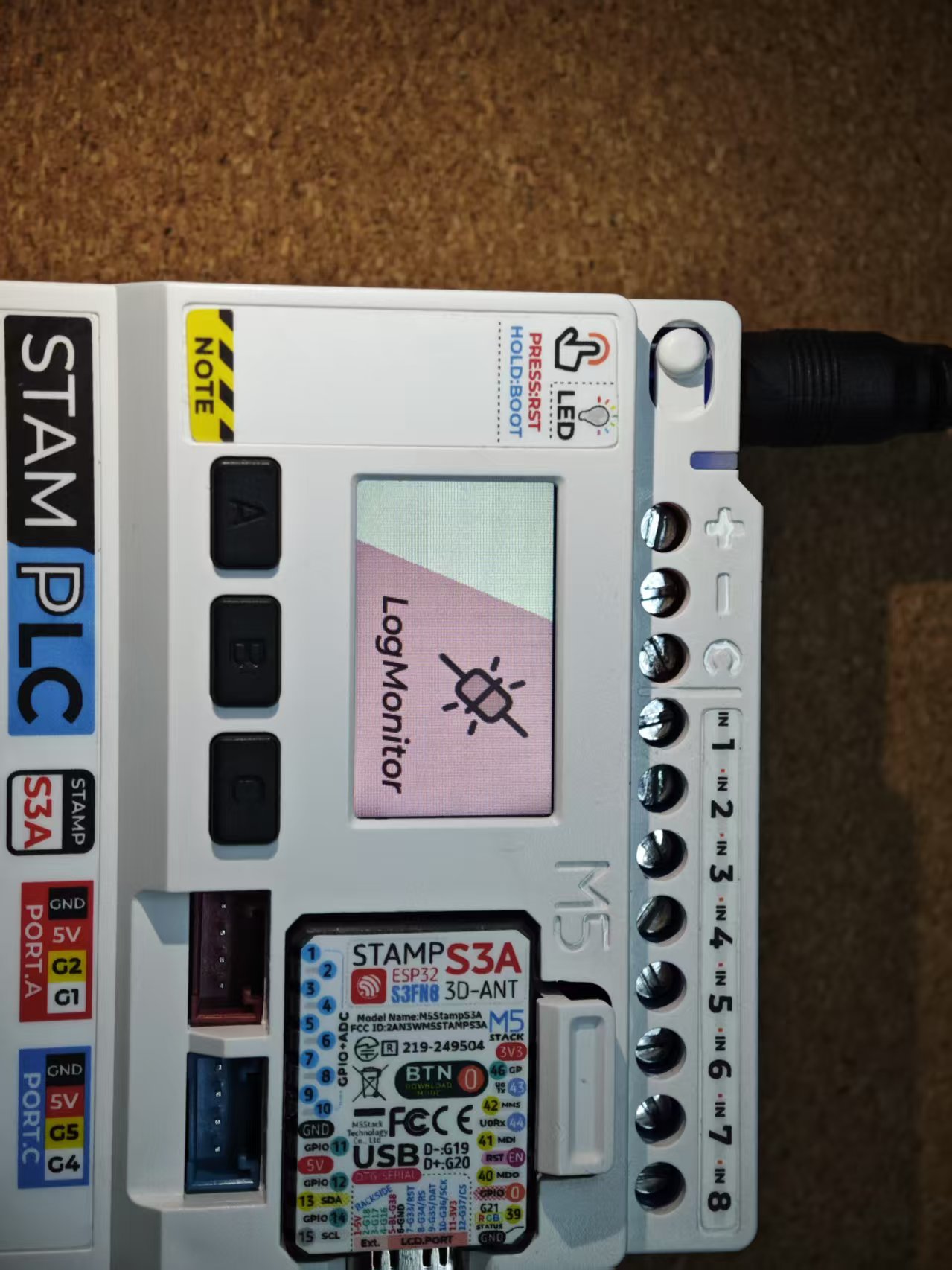
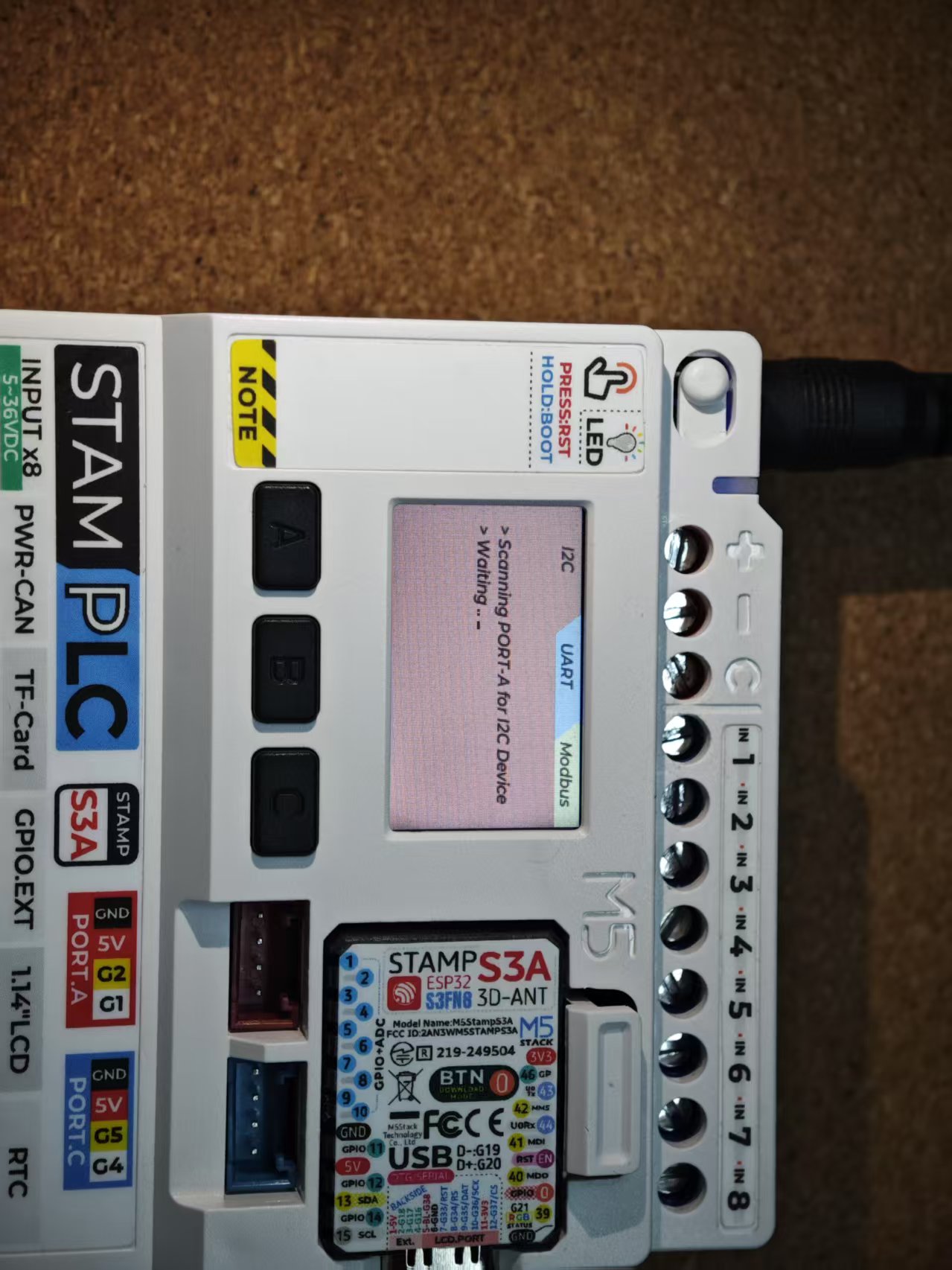
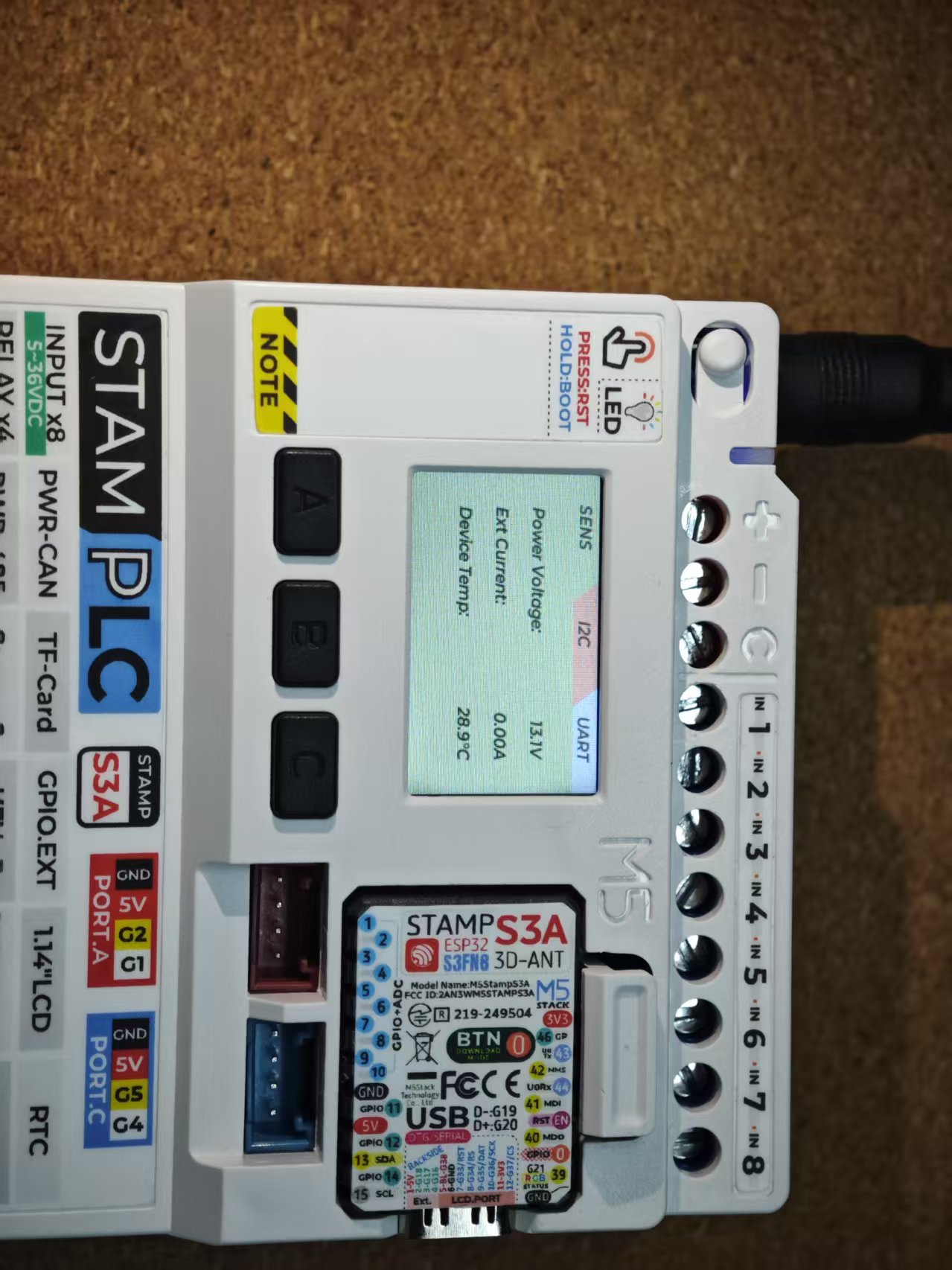
4. LogMonitor
The StamPLC LogMonitor function is used to monitor the status of several communication interfaces and internal sensors.
5. TimerRelay
StamPLC TimerRelay allows you to set the relays to operate with a specified on/off cycle. This function is for testing purposes only; it will automatically pause after the device is reset or when you exit the page.


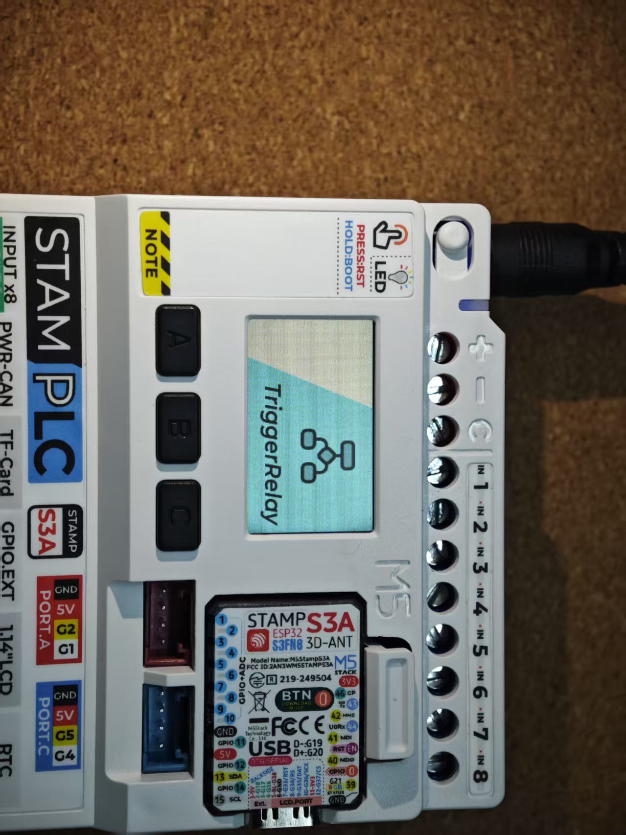
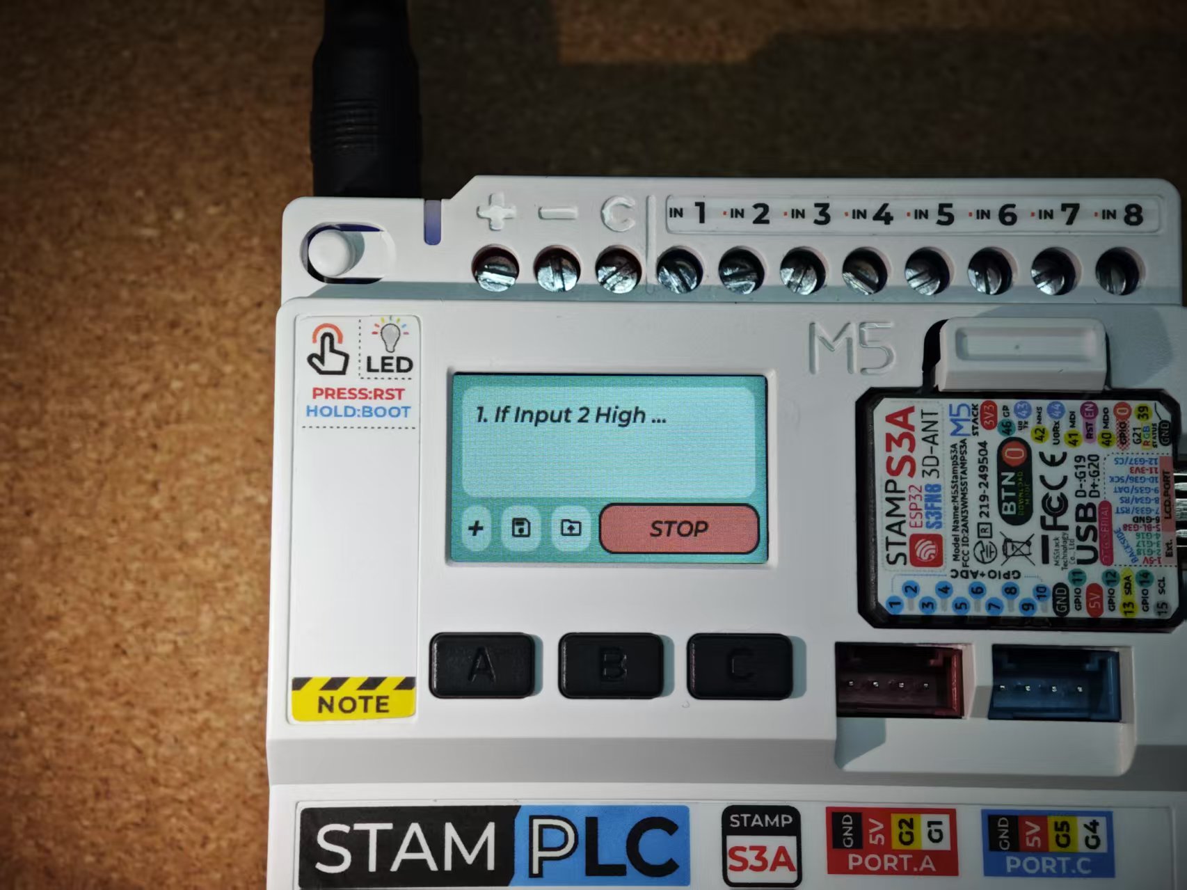
6. TriggerRelay
StamPLC TriggerRelay is used to monitor the status of the 8-channel input signals. When the signal status meets the set trigger conditions, you can configure it to execute corresponding actions. For example, when an input signal is high, a specific relay can be triggered to close. It also supports saving trigger presets to the SD card. This function is for testing purposes only; it will automatically pause after the device is reset or when you exit the page.

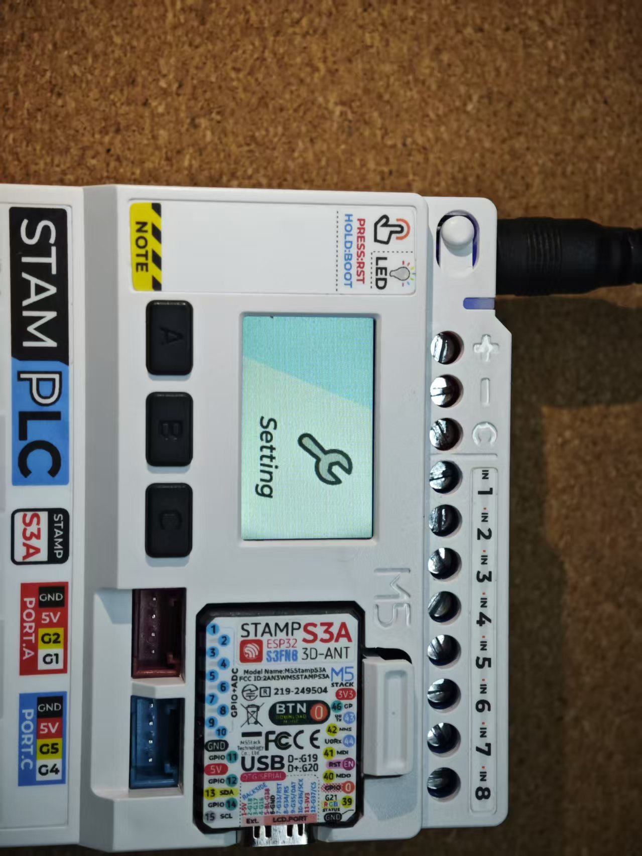
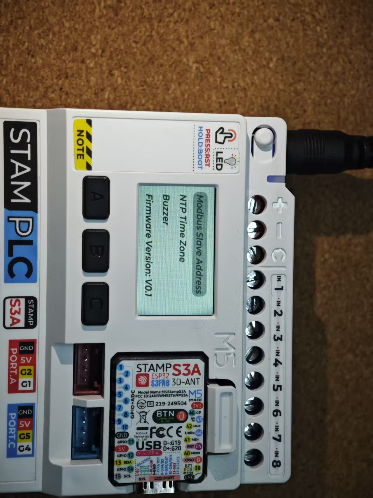
7. Setting
View the device firmware version and configure the Modbus slave address, buzzer, and the timezone (UTC) displayed on the RTC clock.
8. Modbus Slave
After the StamPLC firmware starts by default, it will automatically initialize as a Modbus slave. External devices can control the device via the PWR-485 interface using the Modbus RTU protocol. The specific register protocol is as follows.
Register Map:
Coils (Read/Write)
- Address 0: Relay 1 output (true/false)
- Address 1: Relay 2 output (true/false)
- Address 2: Relay 3 output (true/false)
- Address 3: Relay 4 output (true/false)
Input Registers (Read-only)
- Address 0-7: Inputs (true/false) - 8 registers
- Address 8-9: Temperature (FLOAT32) - 2 registers
- Address 10-11: Bus Voltage (FLOAT32) - 2 registers
- Address 12-13: Shunt Current (FLOAT32) - 2 registers