pdf-icon

V-function

This tutorial is suitable for M5StickV/UnitV

Function Introduction

V-Function is a set of multiple visual recognition firmware developed by the M5Stack team for V-series devices. Based on different firmware functions (object tracking, motion detection, etc.), users can quickly build visual recognition functions. This tutorial will introduce you to how to burn firmware to your device and call it through UIFlow graphical programming.

The firmware serial output baud rate is fixed at 115200

Driver Installation

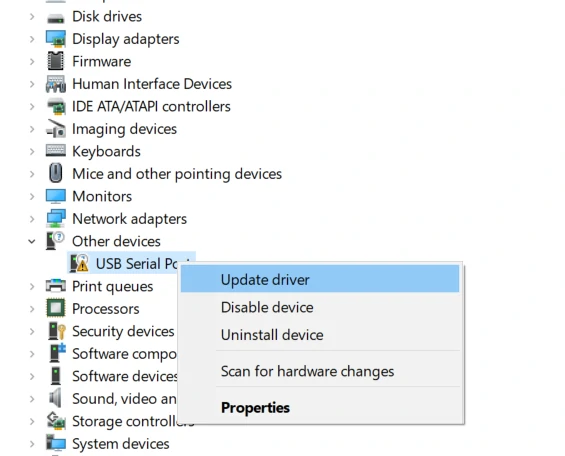
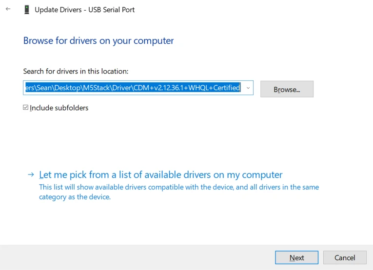
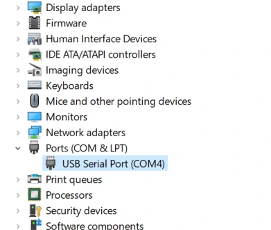
Connect the device to the PC, open Device Manager to install the FTDI driver for the device. For example, in a win10 environment, download the driver file that matches the operating system, and unzip it. Install it through Device Manager. (Note: In some system environments, you may need to install it twice for the driver to take effect. The unrecognized device name is usually M5Stack or USB Serial. Windows recommends using the driver file directly in Device Manager for installation (custom update). The executable file installation method may not work properly). Click here to download the FTDI driver
For MacOS users, please check System Preferences -> Security & Privacy -> General -> Allow apps downloaded from: -> App Store and identified developers.

Burn Firmware

Please download the corresponding M5Burner firmware burning tool according to the operating system you are using, and unzip and open the application.

Software Version Download Link
M5Burner_Windows Download
M5Burner_MacOS Download
M5Burner_Linux Download
Note:
For MacOS users, after installation, please put the application into the Application folder as shown below.
For Linux users, switch to the decompressed file path, and run ./M5Burner in the terminal to run the application.

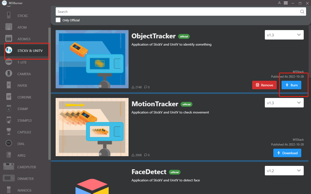
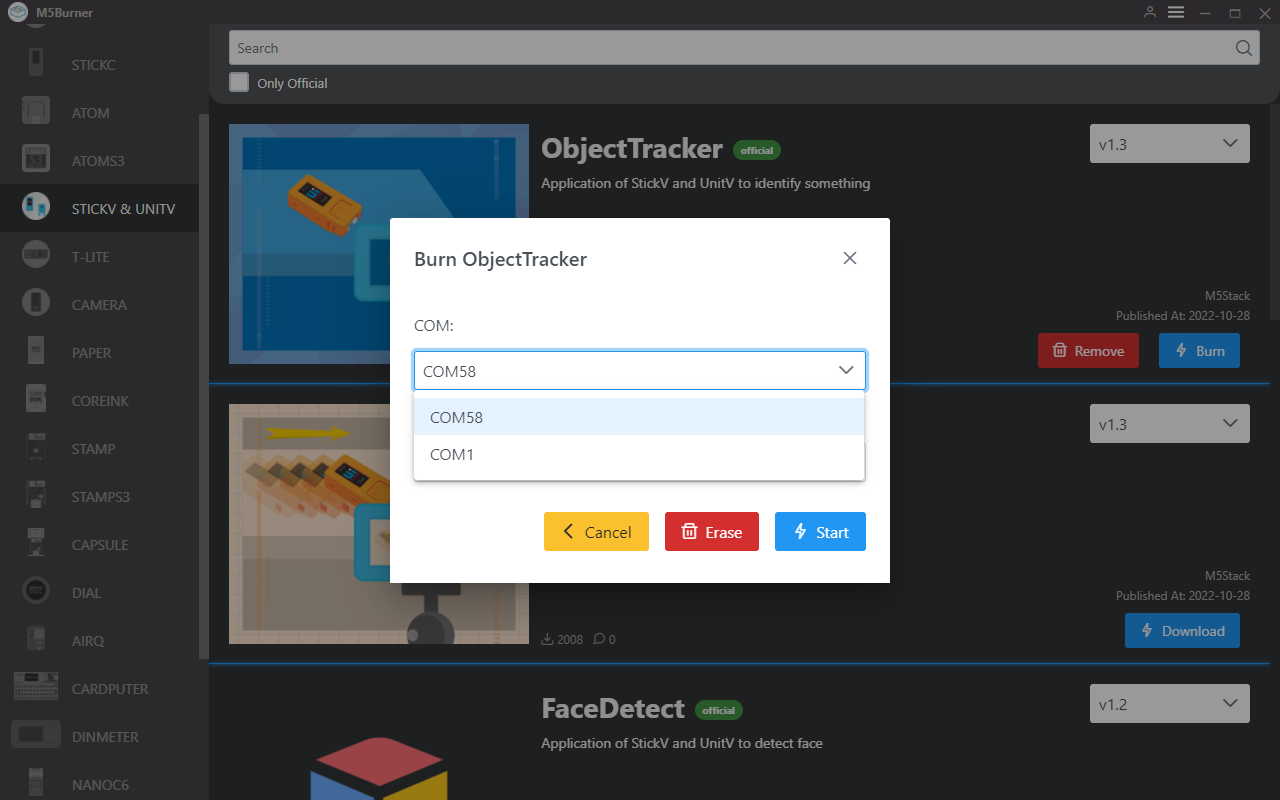
Select the device as M5StickV/UnitV from the left device bar, choose the corresponding functional firmware according to your needs, and download it. Connect the M5StickV/UnitV to the computer via a data cable, select its corresponding port, and click Burn to start burning.

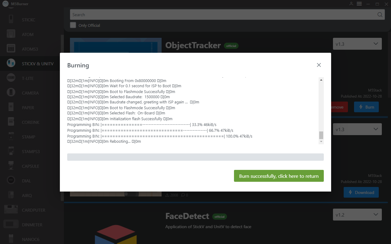
When the burning log prompts Burn Successfully, it means that the firmware has been burned successfully.

UIFlow Reference

Import Extensions

After burning the functional firmware, the M5StickV/UnitV will be used as a slave device in the form of Unit. Therefore, users need to use other M5 host devices to interact with it. For basic usage and operation of UIFlow on other main control products, please visit the corresponding product documentation page for reference.

Visit https://flow.m5stack.com/ to enter UIFlow. Click the Unit add button on the right function panel, select the UnitV extension to add. When adding, please configure according to the actual port used. Click OK to add.

After adding, you can find the functional blocks containing in the Unit option in the function block menu. Drag it to the right programming area to use it. For more details, please refer to the example program below.

Notes

If there is abnormal data acquisition on the main control end after connecting the slave device (M5StickV/UnitV), please restart the M5StickV/UnitV. Wait for the firmware to start successfully and try to reconnect.

Motion Detection

Detect changes in the current frame to determine whether there is motion in the detected area.

Program Block Introduction

  • Initialize

    • Initialize
  • Set Change Rate Threshold

    • Set the change rate threshold: When the change amount is less than this value of pixels, it will not be considered as a change, and its change amount will not be included in the frame change rate.
  • Set Detection Mode

    • dynamic: Dynamic detection mode, continuously takes pictures and compares the changes between the previous and current frames.
    • static: Static detection mode, after execution, it will take and save a base picture. Subsequent frames will be continuously compared with this picture. If you need to take a new base picture, you need to switch back to dynamic detection mode first, and then execute static detection mode setting again.
  • Get Frame Change Rate

    • Frame change rate: the change amount of pixels between the previous and current frames. Suppose there are 2 pixels that have changed, pixel A has changed by 27, pixel B has changed by 10, then this value is 27+10=37. The value is the sum of the difference in the R.G.B components of the two pixels.
  • Get Maximum Change Rate

    • Maximum change rate: the change amount of the most intense pixel.
  • Set Scan Interval X Axis Y Axis

    • Set the scan interval on the x-axis and y-axis.
  • Get Boundary Box Number

    • Get the number of boundary boxes generated by pixel changes.
  • Get X Number Boundary Box Information

    • Return detailed information of the Xth boundary box as a list, including the number of changed pixels in the boundary box, the x-axis coordinate

of the boundary box, the y-axis coordinate of the boundary box, the width of the boundary box, and the height of the boundary box.

Program Example: Enable dynamic detection mode, judge the presence of motion in the frame based on the size of the maximum change rate value read from the frame. Display "Moved" when the change rate value is greater than the expected value, otherwise display "Not Move". The screen displays the current maximum change rate value.

Motion Detection - Data Packet Format

Return JSON

{
    "FUNC": "MOTION DETECT V1.0",
    "DIFF TOTAL": 10000, // Frame change rate
    "DIFF MAX": 75, // Maximum change rate
    "TOTAL": 3, // Number of boundary boxes
    "0": {
        "x": 45,
        "y": 18,
        "w": 126,
        "h": 72,
        "area": 342 // Number of changed pixels in this boundary box
    },
    "1": {
        "x": 0,
        "y": 169,
        "w": 130,
        "h": 24,
        "area": 173
    },
    "2": {
        "x": 39,
        "y": 204,
        "w": 276,
        "h": 34,
        "area": 141
    }
}

Setting JSON

{
    "MOTION DETECT": 1.0, // Function flag, cannot be omitted
    "mode": "COMPUTE_MODE_STATIC", // Optional "COMPUTE_MODE_STATIC" static detection mode or "COMPUTE_MODE_DYNAMIC" dynamic detection mode
    "thr_w": 20, // Optional Width threshold of the boundary box,[3,200]
    "thr_h": 20, // Optional Height threshold of the boundary box,[3,200]
    "stepx": 1, // Optional X-axis scan interval,[0, 40], set to 0 to disable boundary box detection
    "stepy": 2, // Optional Y-axis scan interval,[0, 40], set to 0 to disable boundary box detection
    "delta": 20, // Optional Change rate threshold,[0, 99]
     "merge": 10 // Optional Boundary box merge threshold,[0, 40]
}

Object Tracking

Set the tracking target and obtain the real-time position information of the target object in the frame.

Program Block Introduction

  • Initialize

    • Initialize
  • Set Tracking Box Coordinates x y Tracking Box Width Height

    • Set the target selection box, parameters are the position of the current target on the image (select a target with significant color features as much as possible)
  • Get Tracking Box Trajectory Details

    • Read the coordinates of the selected target on the image, and the return value is in the form of a list, which includes the x, y coordinates of the upper left corner of the selection box, and the width and height of the selection box.

Program Example: Set the target selection box by pressing button A, read the target coordinates, and use them to control the movement of rectangular elements on the screen to simulate the motion trajectory of objects.

Object Tracking - Data Packet Format

Return JSON

{
    "FUNC": "TARGET TRACKER V1.0",
    "x": 282,
    "y": 165,
    "w": 13,
    "h": 15
}

Setting JSON

{
    "TARGET TRACKER": " V1.0",
    "x": 282, //xywh cannot be omitted
    "y": 165,
    "w": 13,
    "h": 15
}

Color Tracking

Set LAB color thresholds to track targets in the image that meet the threshold, and obtain real-time position information of the target object in the image.

Program Block Introduction

  • Initialize

    • Initialize.
  • Set Target Color L Threshold Min 0 L Threshold Max 0 A Threshold Min A Threshold Max B Threshold Min B Threshold Max

    • Set the LAB threshold for tracking (LAB color space values, colors outside this range will be filtered).
  • Set Scan Interval X Axis Y Axis

    • Set the scan interval on the X-axis and Y-axis, [0, 40]. Set to 0 to disable boundary box detection.
  • Set Boundary Box Merge Threshold

    • Set the boundary box merge threshold.
  • Set Boundary Box Width Threshold 0 Height Threshold 0

    • Set the boundary box width threshold 0 and height threshold 0.
  • Get Boundary Box Number

    • Get the number of boundary boxes.
  • Get Boundary Box Details

    • Get the details of the boundary box, including the number of changed pixels in the boundary box, the x-axis coordinate of the boundary box, the y-axis coordinate of the boundary box, the width of the boundary box, and the height of the boundary box.

Setting LAB Thresholds

Click the button below to download the LAB color picking tool. (Currently only supports Windows systems)

Download LAB Color Picking Tool

Use a phone or other device to take a sample picture, double-click to open the application, click open --> image to import the picture.

Click on the object you want to use for color recognition, record the LAB values generated below, and configure them for use in UIFlow. Note: Dragging the range bar of LAB values can be used to customize the LAB values.

Program Example: Set the recognized LAB threshold, achieve color tracking effect, and obtain the coordinate data of the tracked object in the image, and the number of pixels that meet the threshold.

Color Tracking - Data Packet Format

Return JSON

{
    "FUNC": "COLOR TRACKER V1.0",
    "TOTAL": 3, // Number of boundary boxes
    "0": {
        "x": 45,
        "y": 18,
        "w": 126,
        "h": 72,
        "area": 342 // Number of changed pixels in this boundary box
    },
    "1": {
        "x": 0,
        "y": 169,
        "w": 130,
        "h": 24,
        "area": 173
    },
    "2": {
        "x": 39,
        "y": 204,
        "w": 276,
        "h": 34,
        "area": 141
    }
}

Setting JSON

{
    "COLOR TRACKER": 1.0, // Function flag, cannot be omitted
    "thr_w": 20, // Optional Width threshold of the boundary box,[3,200]
    "thr_h": 20, // Optional Height threshold of the boundary box,[3,200]
    "stepx": 1, // Optional X-axis scan interval,[0, 40], set to 0 to disable boundary box detection
    "stepy": 2, // Optional Y-axis scan interval,[0, 40], set to 0 to disable boundary box detection
    "merge": 10, // Optional Boundary box merge threshold,[0, 40]
    "Lmin": 0, // Optional L threshold lower limit [0, 100]
    "Lmax": 0, // Optional L threshold upper limit [0, 100]
    "Amin": 0, // Optional A threshold lower limit [0, 255]
    "Amax": 0, // Optional A threshold upper limit [0, 255]
    "Bmin": 0, // Optional B threshold lower limit [0, 255]
    "Bmax": 0, // Optional B threshold upper limit [0, 255]
}

Face Detection

Recognize faces in the image and return the number of recognitions, object coordinates, and confidence level.

Program Block Introduction

  • Initialize

    • Initialize
  • Get Number of Faces

    • Read the number of faces recognized.
  • Get Details of the xth Face

    • Read the details data of the specified number of faces, returned in list format, including the coordinates of the face box, length, width, and confidence level.

Program Example: Read the face recognition results in the image and the confidence level.

人脸识别-数据包格式

回传JSON

{
   "FUNC": "FACE DETECT",  // 功能说明
   "count": 3,   // 识别到的人脸数量
   "2": {  // 人脸编号
      "x": 97,    // ROI
      "y": 26,
      "w": 64,
      "h": 86,
      "value": 0.859508,  // 置信率
       "classid": 0,  
       "index": 2,
       "objnum": 3
        },
    "1": {
       "x": 70,
       "y": 157,
       "w": 38,
       "h": 63,
       "value": 0.712100,
       "classid": 0,
       "index": 1,
       "objnum": 3
       },
    "0": {
       "x": 199,
       "y": 145,
       "w": 31,
       "h": 40,
       "value": 0.859508,
       "classid": 0,
       "index": 0,
       "objnum": 3
       }
    }

Face Recognition - Data Packet Format

JSON Response

{
   "FUNC": "FACE DETECT",
   "count": 3,
   "2": {
      "x": 97,
      "y": 26,
      "w": 64,
      "h": 86,
      "value": 0.859508,
      "classid": 0,
      "index": 2,
      "objnum": 3
   },
   "1": {
      "x": 70,
      "y": 157,
      "w": 38,
      "h": 63,
      "value": 0.712100,
      "classid": 0,
      "index": 1,
      "objnum": 3
   },
   "0": {
      "x": 199,
      "y": 145,
      "w": 31,
      "h": 40,
      "value": 0.859508,
      "classid": 0,
      "index": 0,
      "objnum": 3
   }
}

QR Code Recognition

Recognize QR codes in the image and return the recognition results along with the version. Using firmware Find code.

Program Blocks Overview

  • Initialize

    • Initialization
  • Get QR Code Information

    • Read the content of the recognized QR code
  • Get QR Code Version

    • Read the version of the recognized QR code

Program Example: Read QR code information and version number.

JSON Response

{
   "count": 1,
   "FUNC": "FIND QRCODE",
   "0": {
      "x": 57,
      "y": 16,
      "w": 197,
      "h": 198,
      "payload": "m5stack",
      "version": 1,
      "ecc_level": 1,
      "mask": 2,
      "data_type": 4,
      "eci": 0
   }
}

Barcode Recognition

Recognize barcodes in the image and return the recognition results along with the version. Using firmware Find code.

Program Blocks Overview

  • Initialize

    • Initialization
  • Get Recognized Barcode Content

    • Read the content of the recognized barcode
  • Get Recognized Barcode Rotation Angle

    • Read the rotation angle of the recognized barcode
  • Get Recognized Barcode Type

    • Read the type of the recognized barcode
  • Get Recognized Barcode Position Information

    • Read the selected coordinates, length, and width of the recognized barcode, returning a list

Program Example: The example reflects barcode information, barcode type, barcode rotation angle, and detailed position information of the barcode.

JSON Response

{
    "0": {
        "x": 62,
        "y": 90,
        "w": 100,
        "h": 45,
        "payload": "123",
        "type": 15,
        "rotation": 0.000000,
        "quality": 28
    },
    "count": 1,
    "FUNC": "FIND BARCODE"
}

DataMatrix Code Recognition

Recognize DataMatrix codes in the image and return the recognition results along with rotation angle, and coordinate data. Using firmware Find code.

Program Blocks Overview

  • Initialize

    • Initialization
  • Get Data Matrix Code Information

    • Read the content of the recognized DataMatrix code
  • Get Data Matrix Code Rotation Angle

    • Read the rotation angle of the recognized DataMatrix code
  • Get Data Matrix Code Position Information

    • Read the selected coordinates, length, and width of the recognized DataMatrix code, returning a list

Program Example: The example reflects DataMatrix code information, rotation angle, and detailed position information.

JSON Response

{
    "0": {
        "x": 20,
        "y": 116,
        "w": 96,
        "h": 96,
        "payload": "m5stack",
        "rotation": 1.588250,
        "rows": 16,
        "columns": 16,
        "capacity": 12,
        "padding": 1
    },
    "count": 1,
    "FUNC": "FIND DATAMATRIX"
}

AprilTag Code Recognition

Recognize AprilTag codes (supports only Tag36H11 type) in the image, and obtain their positional offsets. Use firmware Find Code.

Program Blocks Introduction

  • Initialize

    • Initialize
  • Get Rotation Angle of AprilTag Code

    • Returns the rotation angle of the AprilTag in radians (int)
  • Get Coordinates of AprilTag Code

    • Reads the selected coordinates, center coordinates, length, and width of the recognized AprilTag code, the return value is a list.
  • Get Movement Units of AprilTag Code

    • Reads the position offset of the AprilTag code.

Program Example: The example reflects the rotation angle, movement units, and detailed positional information of the AprilTag code.

JSON Feedback

{
    "0": {
        "x": 71,
        "y": 5,
        "w": 85,
        "h": 88,
        "id": 1,
        "family": 16,// AprilTag category
        "cx": 115,
        "cy": 49,
        "rotation": 6.219228,// Rotation angle of AprilTag in radians (int).
        "decision_margin": 0.451959,// Color saturation of AprilTag matching (values from 0.0 to 1.0), where 1.0 is optimal.
        "hamming": 0,// Acceptable number of bit errors for AprilTag
        "goodness": 0.000000, // Color saturation of AprilTag image
        "x_translation": 0.868200, // Number of units to move the image left or right after rotation
        "y_translation": 0.245313,// Number of units to move the image up or down after rotation
        "z_translation": -2.725188,// Amount scaled by the image. Default is 1.0
        "x_rotation": 3.093776,// Degrees to rotate the image around the x-axis in the frame buffer
        "y_rotation": 0.065489,// Degrees to rotate the image around the y-axis in the frame buffer
        "z_rotation": 6.219228 // Degrees to rotate the image around the z-axis in the frame buffer
    },
    "count": 1,
    "FUNC": "FIND APRILTAG"
}

JSON for Setting Recognition Mode

The various recognition code functionalities above are all implemented using the same firmware Find Code. Users can switch modes by sending the following JSON data.


{
    "FIND CODE": 1.0,
    "mode":"DATAMATRIX" // Recognition mode, options: QRCODE, APRILTAG, DATAMATRIX, BARCODE
}

Custom Tag Recognition

Detect tag cards in the image and return binary sequences. Note: Only fixed tag card formats are recognized, please refer to the image below.

Program Blocks Introduction

  • Initialize

    • Initialize
  • Get Current Number of Recognized Tag Cards

    • Number of tag cards recognized in the current image
  • Get Binary String of Recognition Result

    • Binary data string of recognition result, when there are multiple cards, pass the index to select different card contents.
  • Get uint64_t Type Code Content

    • uint64_t type content binary code, maximum encoding of 64 bits (8 x 8) TAG.
  • Get Positional Information of Tags

    • Coordinates and length-width information of tag cards
00000000      00000000              
00111100      00@@@@00        @@@@  
01000010      0@0000@0       @    @ 
01000010  ->  0@0000@0  ->   @    @ 
01011010      0@0@@0@0       @ @@ @ 
01000010      0@0000@0       @    @ 
01000010      0@0000@0       @    @ 
00000000      00000000              

Tag Reader Example

Custom Tag Recognition - Data Packet Format

JSON Feedback

{
    "FUNC": "TAG READER V2.0",
    "TOTAL": 1,
    "0": {
        "x": 113,
        "y": 65,
        "w": 117,
        "h": 105,
        "p0x": 113, // Coordinates of the 4 vertices of the TAG
        "p0y": 77,
        "p1x": 211,
        "p1y": 65,
        "p2x": 230,
        "p2y": 156,
        "p3x": 127,
        "p3y": 170,
        "rotation": 8, // Relative rotation angle of the TAG
        "rows": 8, // Number of rows of the TAG (excluding the locator frame)
        "columns": 8, // Number of columns of the TAG (excluding the locator frame)
        "size": 64, // Length of the actual content of the TAG, this value = number of rows * number of columns = (rows) * (columns)
        "code": "0x003C42425A424200", // uint64_t type content binary code, maximum encoding of 64 bits (8 x 8) TAG
        "binstr": "0000000000111100010000100100001001011010010000100100001000000000" // Binary data string, this value can encode TAGs of any length and width
    }
}

Line Tracking

Detect specified color lines in the image and return the angle of offset.

Program Blocks Introduction

  • Initialize

    • Initialize
  • Get Line Offset Angle

    • Obtain the angle offset of the line
  • Set Tracking Target Color L Threshold Min L Threshold Max A Threshold Min A Threshold Max B Threshold Min B Threshold Max

    • Set LAB thresholds for tracking (LAB color space values, colors outside this range will be filtered)
  • Set Line Weight 0 Region Weight, Line Weight 1 Region Weight, Line Weight 2 Region Weight

    • Set line region weights: the three weights correspond to the contribution values of the angles in the three regions in the image. For example, setting a larger value for weight_2 will make the angle change more pronounced when turning.

Setting LAB Thresholds

Refer to the LAB color picker tool usage in the Color Tracking function above, shoot the line and scene to be tracked, and record the LAB values generated below, and configure them in UIFlow.

Program Example: Get the line offset angle and display it on the screen

Line Tracking - Data Packet Format

JSON Feedback

{
    "FUNC": "LINE TRACKER V1.0",
    "angle": 3.8593475818634033 // Angle of turning the car
}

Setting JSON

{
    "LINE  TRACKER": 1.0, // Function flag, cannot be omitted
    "thr_w": 20, // Optional, width threshold of the boundary box, [3,200]
    "thr_h": 20, // Optional, length threshold of the boundary box, [3,200]
    "stepx": 1, // Optional, X scan interval, [0, 40], set to 0 to disable boundary box detection
    "stepy": 2, // Optional, Y scan interval, [0, 40], set to 0 to disable boundary box detection
    "merge": 10, // Optional, boundary box merge threshold, [0, 40]
    "Lmin": 0, // Optional, L threshold lower limit [0, 100]
    "Lmax": 0, // Optional, L threshold upper limit [0, 100]
    "Amin": 0, // Optional, A threshold lower limit [0, 255]
    "Amax": 0, // Optional, A threshold upper limit [0, 255]
    "Bmin": 0, // Optional, B threshold lower limit [0, 255]
    "Bmax": 0, // Optional, B threshold upper limit [0, 255]
    "weight_0": 0.1, // Optional, weight
    "weight_1": 0.3, // Optional, weight
    "weight_2": 0.7  // Optional, weight
}

More Content

GitHub

On This Page