


Product Guide
Linux PC
AI Accelerator Card
LLM-8850 Card
Large Language Models
LLM
Real-Time AI Voice Assistant
XiaoZhi Voice Assistant
AtomS3R-M12 Volcengine Kit
Offline Voice Recognition
Industrial Control
IoT Measuring Instruments
Air Quality
PowerHub
Module13.2 PPS
VAMeter
T-Lite
Input Device
Ethernet Camera
PoECAM
Wi-Fi Camera
Unit CamS3/-5MP
AI Camera
LoRa & LoRaWAN
Motor Control
Restore Factory Firmware
DIP Switch Usage Guide
Module LoRa868 v1.2 DIP Switch Documentation
1. Feature Overview
To avoid pin conflicts when stacking Module LoRa868 v1.2 with the host, the module uses four DIP switches to flexibly reassign key pins.
- The four function pins NSS, BUSY, RST, IRQ can be assigned to different GPIOs via the DIP switches.
- Compatible with various M5Stack hosts: Core (Basic), Core2, CoreS3, etc.
- Users can adjust the pin mappings as needed to ensure stable system operation.

2. DIP Switch Overview
2.1 Physical Location of DIP Switches
The four DIP switches are located on the bottom of the module, as shown in the red frames below.
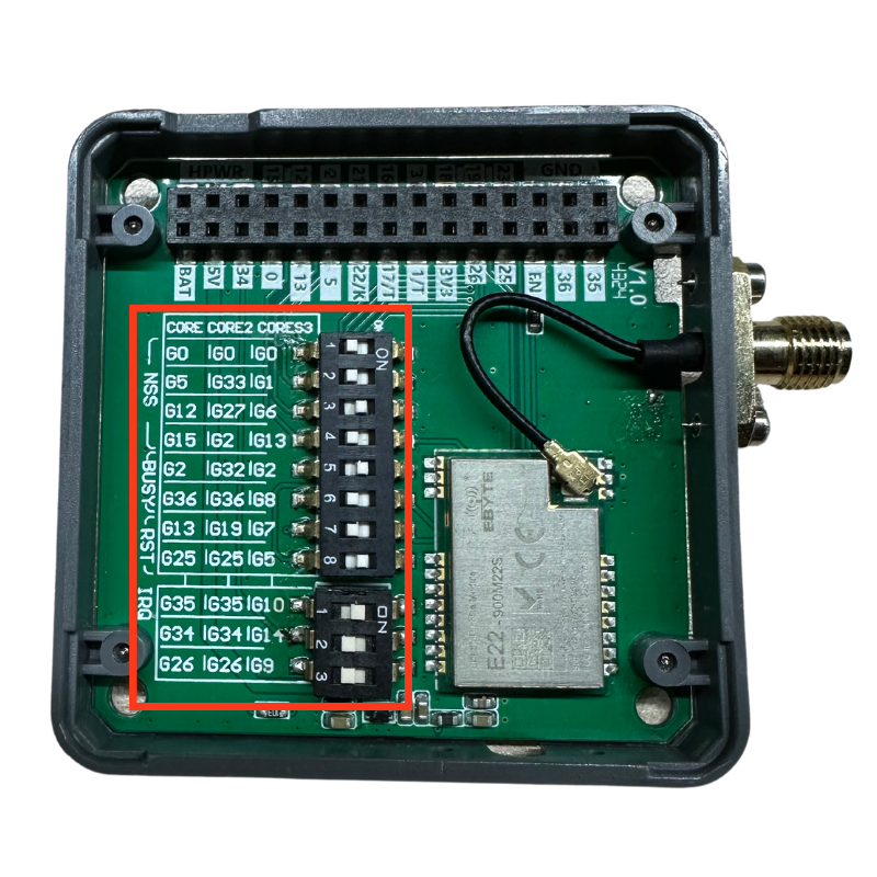
2.2 Pin Mapping Table
Depending on the host, the available mappings for the key pins are as follows:
| Module Model | MOSI | MISO | SCK | RST | BUSY | NSS | IRQ |
|---|---|---|---|---|---|---|---|
| Core (Basic) | G23 | G19 | G18 | G25 / G13 | G36 / G2 | G15 / G12 / G5 / G0 | G35 / G34 / G26 |
| Core2 | G23 | G38 | G36 | G25 / G19 | G36 / G32 | G2 / G27 / G33 / G0 | G35 / G34 / G26 |
| CoreS3 | G37 | G35 | PB4 | G5 / G7 | G8 / G2 | G13 / G6 / G1 / G0 | G10 / G14 / G9 |
For example, when using Module LoRa868 v1.2 with a Core (Basic) host, refer to the first row for the mapping:
- NSS: choose one of G15, G12, G5, or G0
- BUSY: choose one of G36 or G2
- RST: choose one of G25 or G13
- IRQ: choose one of G35, G34, or G26
Set the corresponding DIP switch to the ON side for each selected pin.
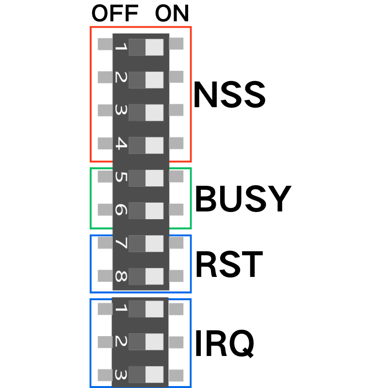
3. DIP Switch Configuration Example
Below is an example configuration for Core (Basic) + Module LoRa868 v1.2, showing how to set the four DIP switches:

In the above example (Core (Basic) + Module LoRa868 v1.2): NSS → G12 BUSY → G2 RST → G13 IRQ → G35
- After setting the DIP switches, reconnect the module and apply power for use.