


Product Guide
Linux PC
Industrial Control
LLM
Real-Time AI Voice Assistant
AtomS3R-M12 Volcengine Kit
Offline Voice Recognition
Zigbee
IoT Cloud
AWS IoT Core
Ethernet Camera
PoECAM
Wi-Fi Camera
Unit CamS3
AI Camera
LoRa & LoRaWAN
Motor Control
Network
Restore Factory Firmware
DIP Switch Usage Guide
Module GPS v2.0
Module GNSS
Module ExtPort For Core2
Module LoRa868 V1.2
Module LLM Serial Communication Pin Switching Tutorial
Pin Switching Description
Because M5Stack's Module series products adopt a stacking design, when multiple products are used simultaneously, pin conflicts may occur. Therefore, Module LLM supports manual switching of communication pins. Since it uses serial communication, the user only needs to adjust the RX and TX pins. Depending on the connected host, you can flexibly choose the appropriate pins.
Pin Switching Position
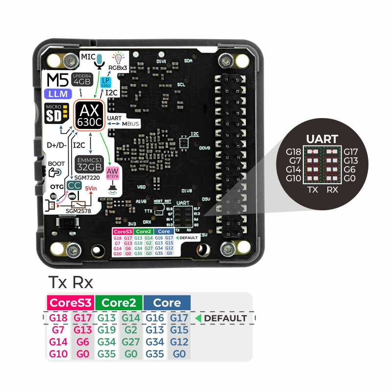
- Pin Mapping
When connecting Module LLM with different hosts, the selectable RX and TX pins are as follows:
| Module LLM | RXD | TXD |
|---|---|---|
| Core (Basic) | G16/G13/G34/G35 | G17/G15/G12/G0 |
| Core2 | G13/G19/G34/G35 | G14/G2/G27/G0 |
| CoreS3 | G18/G7/G14/G10 | G17/G13/G6/0 |
Pin Switching Operation
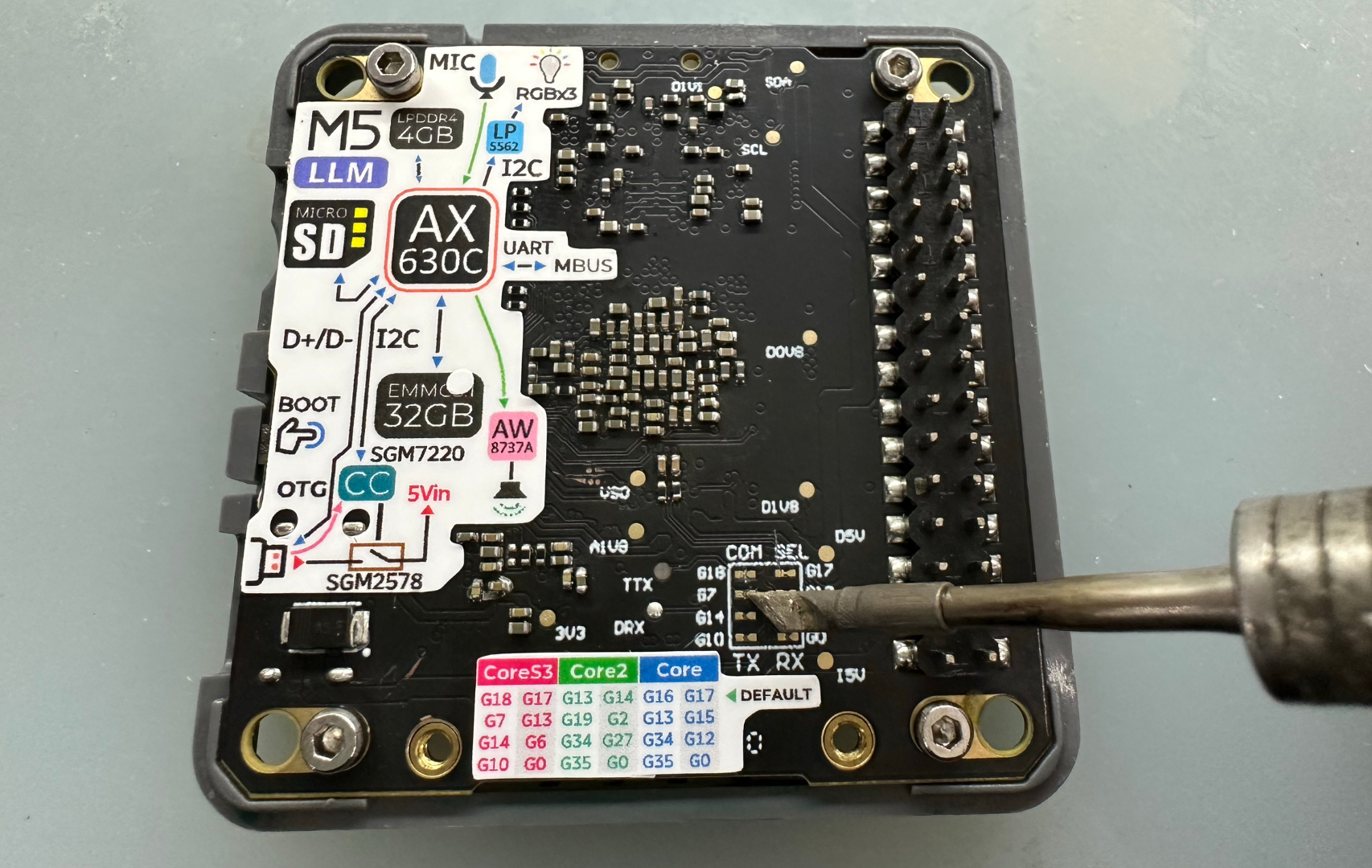
- Taking the CoreS3 + Module LLM pairing as an example, by default, the factory setting uses G18 as TX and G17 as RX for communication.
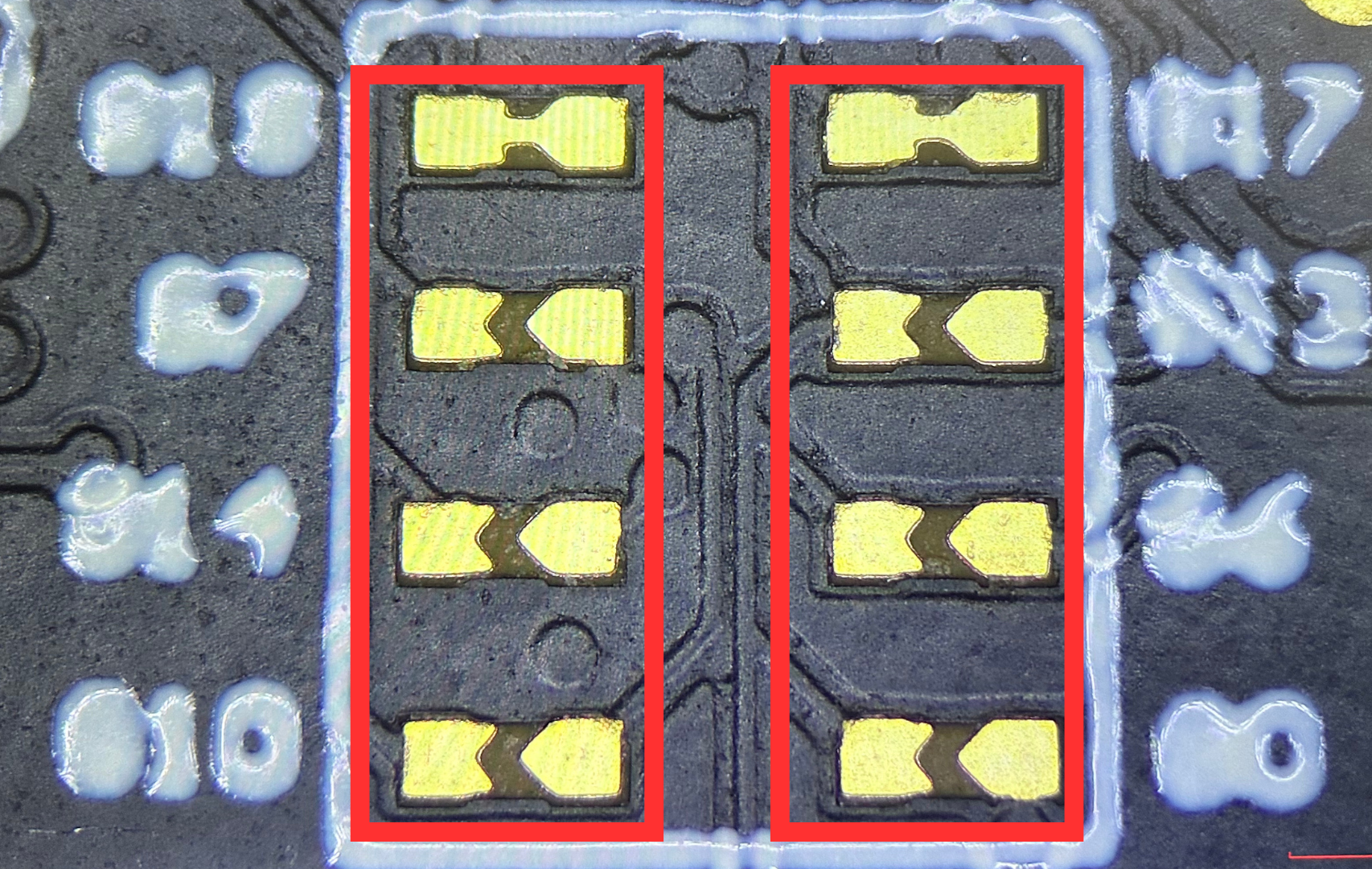
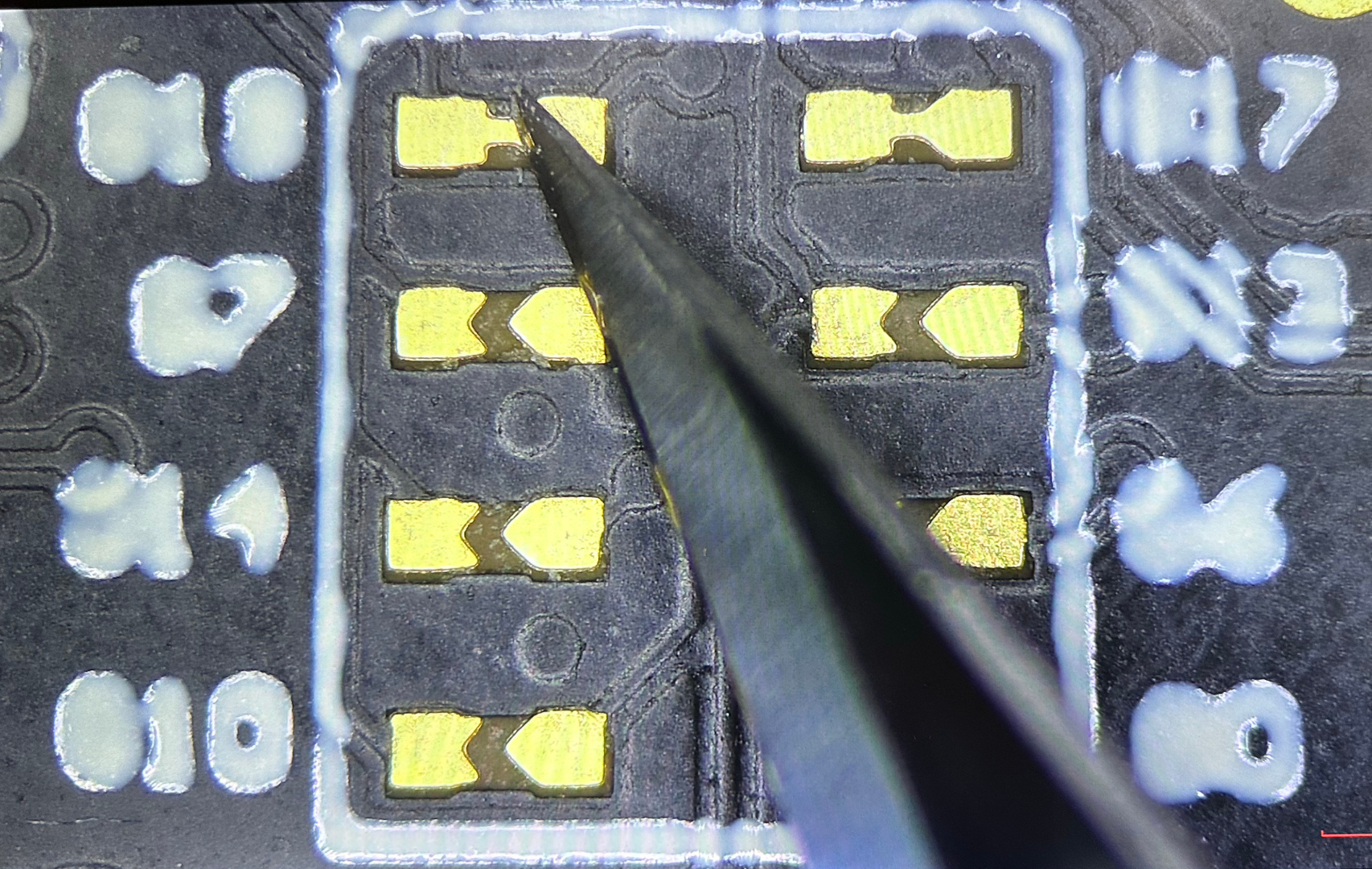
- If you need to switch the TX pin, change it from G18 to G7. Use a blade or other sharp tool to cut the connection between the two solder pads (be careful to avoid injury), and if necessary, use a multimeter to check whether the solder pads have been cut.
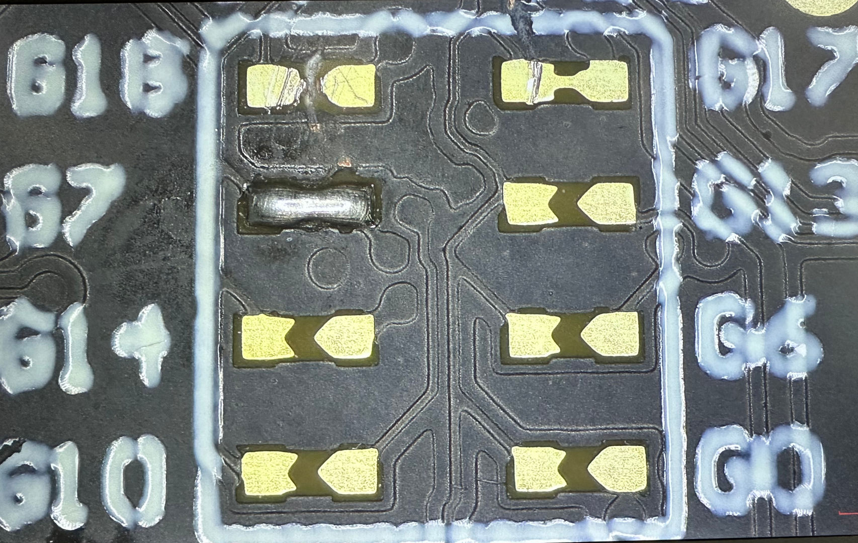
- As shown in the image below, the solder pad connection has been successfully cut:
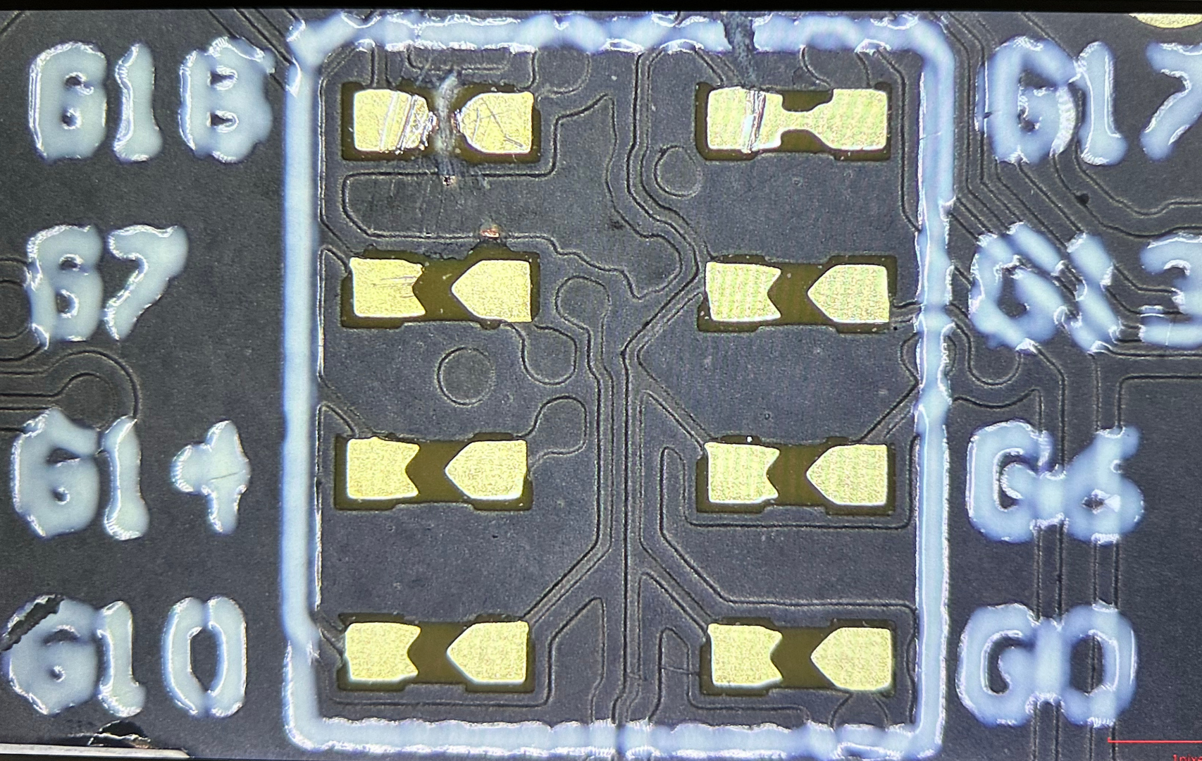
- Then, use a soldering iron to solder the G7 pin.
- The soldering result is as follows:
At this point, you have successfully switched the communication pins of CoreS3 + Module LLM: G7 for TX and G17 for RX. If you need to modify the RX pin, repeat the above steps; both TX and RX pins have four selectable options.