Product Guide
Linux PC
Industrial Control
LLM
Real-Time AI Voice Assistant
AtomS3R-M12 Volcengine Kit
Offline Voice Recognition
Zigbee
IoT Cloud
AWS IoT Core
Ethernet Camera
PoECAM
Wi-Fi Camera
Unit CamS3
AI Camera
LoRa & LoRaWAN
Motor Control
Network
Restore Factory Firmware
DIP Switch Usage Guide
Module GPS v2.0
Module GNSS
Module ExtPort For Core2
Module LoRa868 V1.2
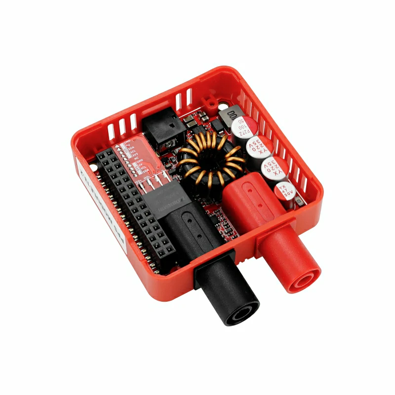
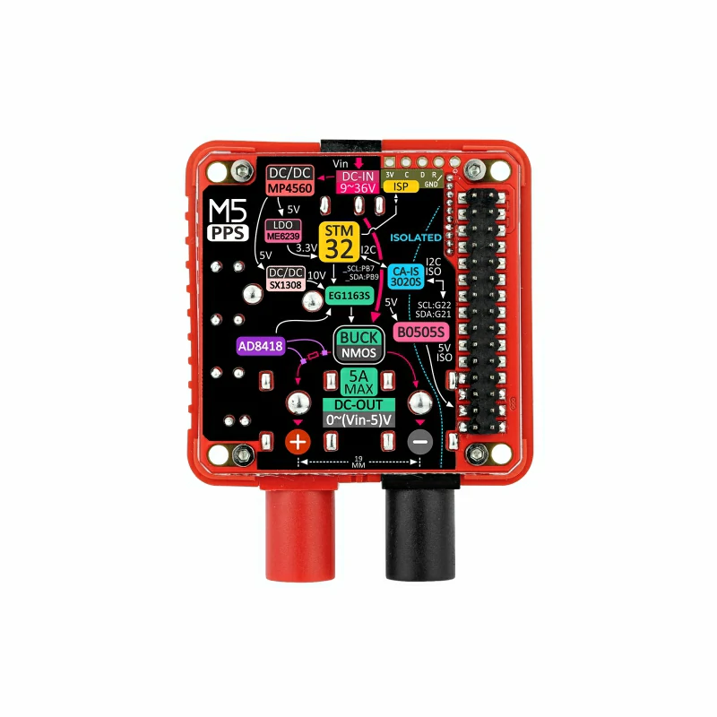
Module13.2 PPS
About This Chapter
Module13.2 PPS is a programmable power supply module. This module adopts STEP-DOWN buck technology and supports a wide voltage DC 9 ~ 36V input range. Built-in with an STM32 control processor and AD8418 high-resolution current amplifier, it achieves rated output power of 100W (peak 150W) for current and voltage output through high-precision closed-loop control. It can output 0.5 ~ 30V/0 ~ 5A, with a readback accuracy of ±30mV/5mA.
This chapter introduces the method to operate rated current and voltage output by stacking Module13.2 PPS with Core/Core2/Core3 series hosts.
Burn Firmware
- According to your operating system, click the button below to download the corresponding M5Burner firmware burning tool. Extract and open the application.
| Software Version | Download Link |
|---|---|
| M5Burner_Windows | Download |
| M5Burner_MacOS | Download |
| M5Burner_Linux | Download |
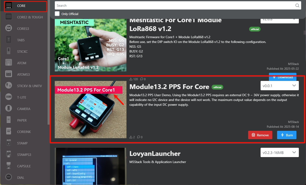
- Double-click to open the Burner burning tool, and find the Demo of Module13.2 PPS corresponding to your host. The Demos for Core/Core2/CoreS3 are as follows:
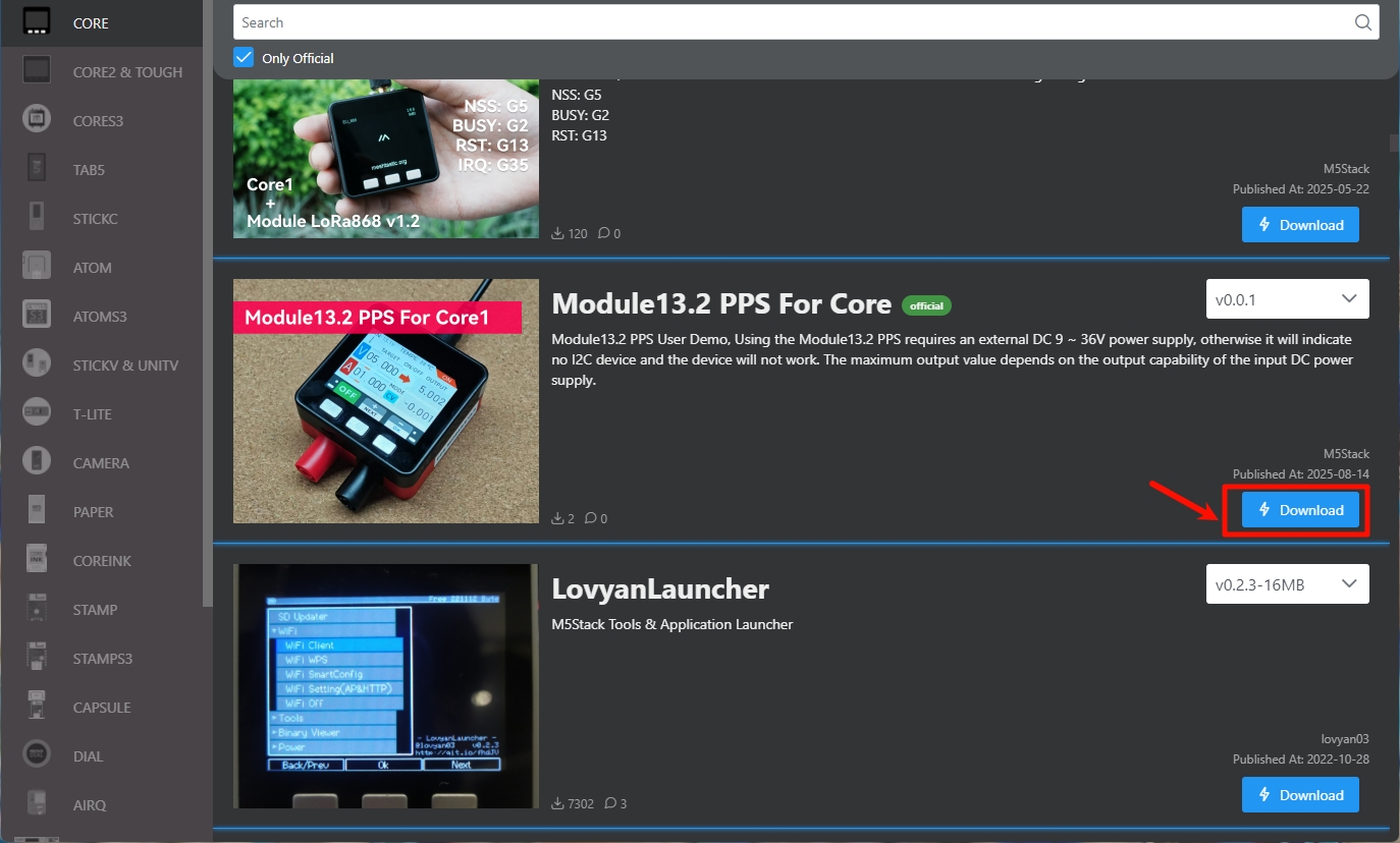
- Demo for Core:
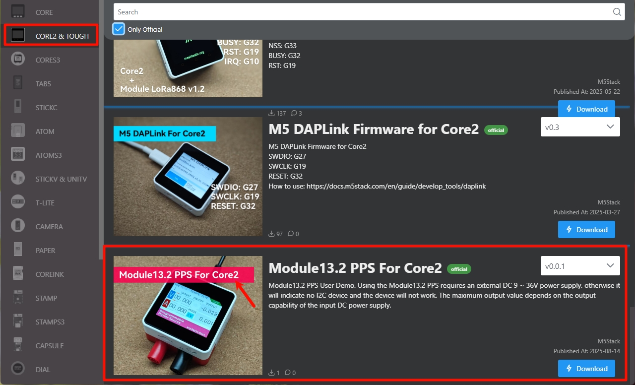
- Demo for Core2:
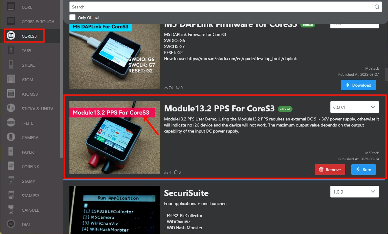
- Demo for CoreS3:
- Click
Downloadto download the Demo compatible with your host.
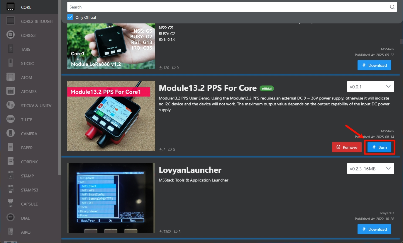
- Connect the device to the computer via USB cable, and click the
Burnbutton for the corresponding Demo.
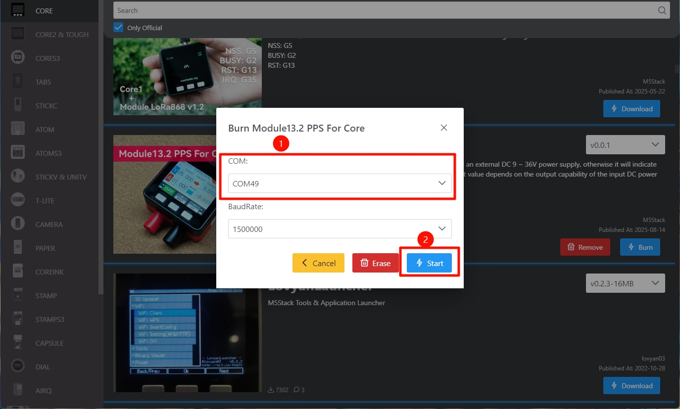
- In the pop-up window, select the port corresponding to your device, and click
Startto begin burning.
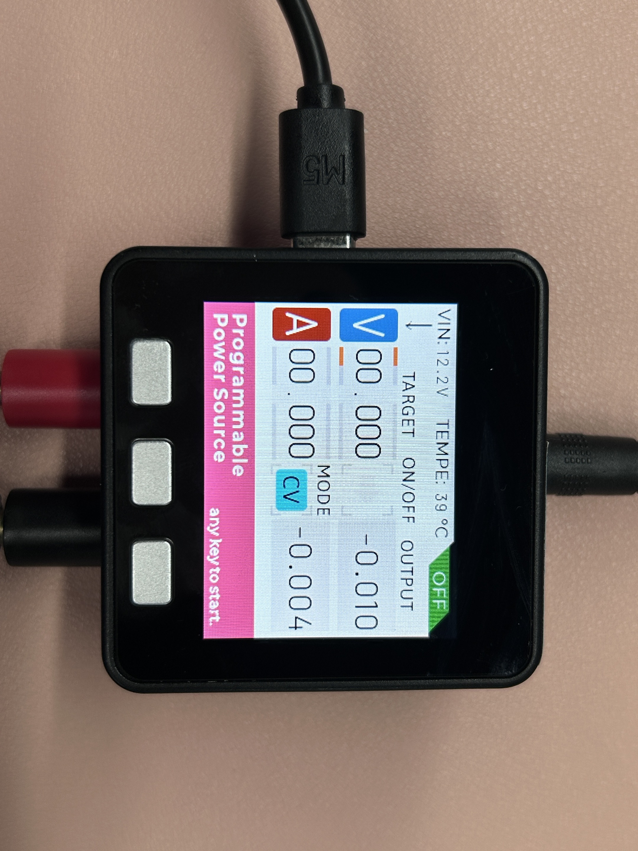
After the firmware burning is completed, the device will automatically enter the current and voltage setting page, as shown below. Press any key to enter the setting mode.
Learn
The current/voltage setting interface is introduced as follows. Core operates via the buttons on the device, while Core2/CoreS3 operates via the touchscreen buttons. The operational effects are the same.
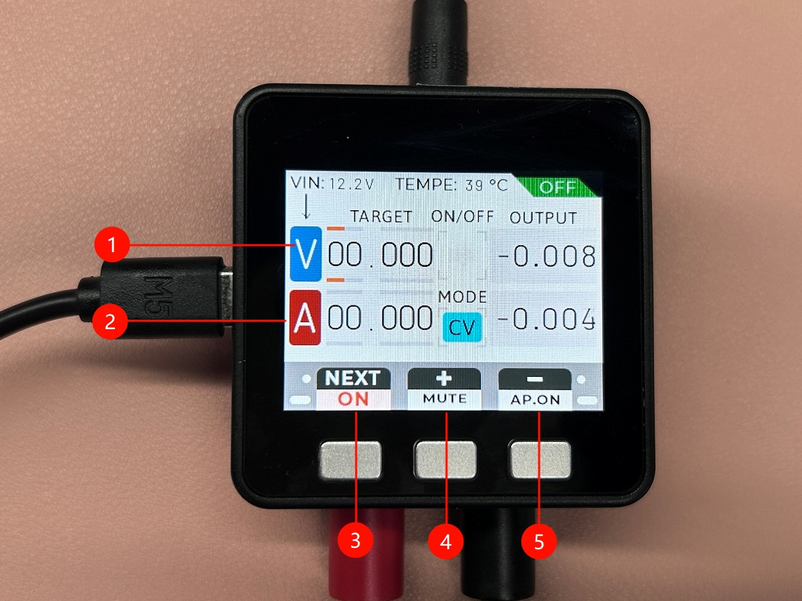
- 1: Set Voltage
- 2: Set Current
- 3: Switch option / Long press to confirm
- 4: Increase value
- 5: Decrease value
For example, the diagram below demonstrates setting a rated output voltage of 5V and output current of 5A. The left side of the interface shows the rated values set. After adjusting using the increase/decrease buttons, long-press ON to confirm and start output. The OUTPUT values on the right indicate the device’s actual current output voltage/current.