Module 4In8Out Arduino Tutorial
1. Preparation
1.Environment Configuration: Follow the Arduino IDE Getting Started Guide to complete the IDE installation, and install the corresponding board management and necessary driver libraries based on the development board you're using.
2.Libraries:
3.Hardwares:


2. Example
Wiring Diagram
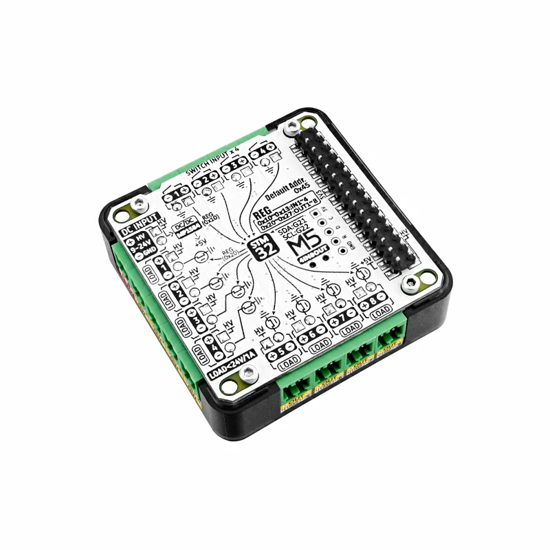
- 4x Input Interfaces:
- Input voltage must be < 5V.
- 8x Output Interfaces:
- The output interface power is supplied through the Power In interface <= 24V, so the appropriate voltage must be supplied at the Power In interface when driving loads. The interface uses MOSFET switches for output control, with a maximum current of 1A per channel.

Full Program
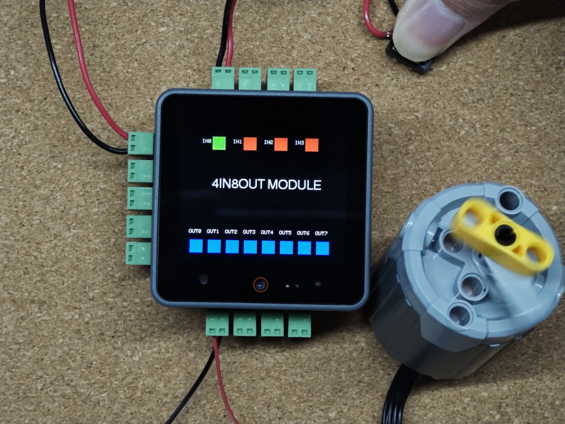
Based on M5Unified and M5GFX, basic display and switch control are added to implement current reading and touch control of the power switch.
#include <M5Unified.h>
#include "MODULE_4IN8OUT.h"

MODULE_4IN8OUT module;

void setup()
{
    M5.begin();

    i2c_port_t i2c_port = M5.In_I2C.getPort();
    i2c_port_t scl_pin  = M5.In_I2C.getSCL();
    i2c_port_t sda_pin  = M5.In_I2C.getSDA();
    auto twowire        = ((i2c_port == 1) ? &Wire1 : &Wire);

    while (!module.begin(twowire, sda_pin, scl_pin, MODULE_4IN8OUT_ADDR)) {
        Serial.println("4IN8OUT INIT ERROR");
        M5.Lcd.println("4IN8OUT INIT ERROR");
        delay(1000);
    };
    Serial.println("4IN8OUT INIT SUCCESS");
}

long interval = 0;
bool level    = false;

void loop()
{
    for (uint8_t i = 0; i < 4; i++) {
        if (module.getInput(i) != 1) {
            M5.Lcd.fillRect(60 + 60 * i, 0, 25, 25, TFT_GREEN);
        } else {
            M5.Lcd.fillRect(60 + 60 * i, 0, 25, 25, TFT_RED);
        }
        M5.Lcd.drawString("IN" + String(i), 40 + 60 * i, 5);
    }
    M5.Lcd.drawString("4IN8OUT MODULE", 60, 80, 4);
    if (millis() - interval > 1000) {
        interval = millis();
        level    = !level;
        for (uint8_t i = 0; i < 8; i++) {
            module.setOutput(i, level);
            if (level) {
                M5.Lcd.fillRect(20 + 35 * i, 200, 25, 25, TFT_BLACK);
                M5.Lcd.fillRect(20 + 35 * i, 200, 25, 25, TFT_BLUE);
            } else {
                M5.Lcd.fillRect(20 + 35 * i, 200, 25, 25, TFT_BLACK);
                M5.Lcd.drawRect(20 + 35 * i, 200, 25, 25, TFT_BLUE);
            }
            M5.Lcd.drawString("OUT" + String(i), 18 + 35 * i, 180);
        }
    }
    delay(500);
}3. Compilation and Upload
1.Download Mode: Before burning the program to different devices, you need to enter download mode. The steps may vary depending on the mainboard. Please refer to the Arduino IDE Getting Started Guide for a list of tutorials at the bottom to see the specific operations.
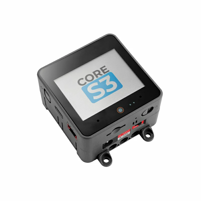
To enter download mode on CoreS3, press and hold the reset button (for about 2 seconds) until the internal green LED lights up, then release it. The device will enter download mode, awaiting the upload.
.gif)
- 2.Select the device port, then click the compile and upload button in the upper-left corner of the Arduino IDE, and wait for the program to compile and upload to the device.

4. Input Monitoring & Output Control

