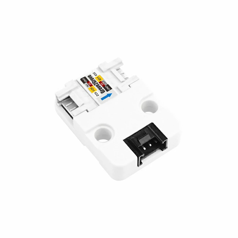
Unit Grove to Grove Arduino Tutorial
1. Preparation
1.Environment Configuration: Follow the Arduino IDE Getting Started Guide to complete the IDE installation, and install the corresponding board management and necessary driver libraries based on the development board you're using.
2.Libraries:
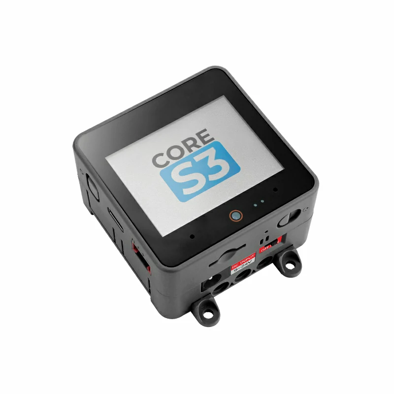
3.Hardwares:


2. Example
Current Calculation
uint32_t adc_raw    = adc1_get_raw((adc1_channel_t)ADC1_CHANNEL_7);
uint32_t voltage_mv = (uint32_t)(esp_adc_cal_raw_to_voltage(adc_raw, adc_chars));
float voltage       = (voltage_mv - offset) / 1000.0f;
float grove_current = (voltage / 50.0f / 0.02f);Power Switch
pinMode(POWER_CTL_PIN, OUTPUT);
// Power on!
digitalWrite(POWER_CTL_PIN, HIGH);
// Power off!
digitalWrite(POWER_CTL_PIN, LOW);Full Program
Based on M5Unified and M5GFX, basic display and switch control are added to implement current reading and touch control of the power switch.
ADC1_CHANNEL_7. If you are using a different mainboard, please refer to the relevant ESP32 chip manual, check the ADC section for the GPIO and channel details, and adjust the example program accordingly.#include <M5Unified.h>
#include "driver/adc.h"
#include "esp_adc_cal.h"
#include "math.h"
#define POWER_CTL_PIN 9
#define ANALOG_PIN 8
esp_adc_cal_characteristics_t *adc_chars;
bool power_status = false;
float offset = 0.0f;
void adc_init()
{
gpio_pad_select_gpio(ANALOG_PIN);
gpio_set_direction((gpio_num_t)ANALOG_PIN, GPIO_MODE_INPUT);
adc1_config_width(ADC_WIDTH_BIT_12);
adc1_config_channel_atten(ADC1_CHANNEL_7, ADC_ATTEN_DB_11);
adc_chars = (esp_adc_cal_characteristics_t *)calloc(1, sizeof(esp_adc_cal_characteristics_t));
esp_adc_cal_characterize(ADC_UNIT_1, ADC_ATTEN_DB_11, ADC_WIDTH_BIT_12, 3300, adc_chars);
}
void cal_adc_offset()
{
float sum = 0;
for (int i = 0; i < 100; i++) {
uint32_t adc_raw = adc1_get_raw((adc1_channel_t)ADC1_CHANNEL_7);
uint32_t voltage_mv = (uint32_t)(esp_adc_cal_raw_to_voltage(adc_raw, adc_chars));
sum += voltage_mv;
}
offset = sum / 100.0f;
}
void setup()
{
M5.begin();
Serial.begin(115200);
pinMode(POWER_CTL_PIN, OUTPUT);
// Power on!
digitalWrite(POWER_CTL_PIN, power_status);
M5.Display.setFont(&fonts::FreeMonoBold12pt7b);
M5.Display.println(power_status ? "Grove Power On" : "Grove Power Off");
adc_init();
cal_adc_offset();
}
time_t last_update_time = 0;
void loop()
{
M5.update();
auto t = M5.Touch.getDetail();
if (t.wasClicked() || M5.BtnA.wasClicked()) {
Serial.println("click!");
power_status = !power_status;
digitalWrite(POWER_CTL_PIN, power_status);
M5.Display.fillRect(0, 0, 320, 50, BLACK);
M5.Display.setCursor(0, 0);
M5.Display.println(power_status ? "Grove Power On" : "Grove Power Off");
if (!power_status) {
cal_adc_offset();
}
}
if (millis() - last_update_time > 1000) {
last_update_time = millis();
M5.Display.fillRect(0, 50, 320, 100, BLACK);
M5.Display.setCursor(0, 50);
uint32_t adc_raw    = adc1_get_raw((adc1_channel_t)ADC1_CHANNEL_7);
uint32_t voltage_mv = (uint32_t)(esp_adc_cal_raw_to_voltage(adc_raw, adc_chars));
float voltage       = (voltage_mv - offset) / 1000.0f;
float grove_current = (voltage / 50.0f / 0.02f);
M5.Display.printf("Grove Current:%.3fA\r\n", grove_current);
Serial.printf("Grove Current:%.3fA\r\n", grove_current);
}
}3. Compilation and Upload
1.Download Mode: Before burning the program to different devices, you need to enter download mode. The steps may vary depending on the mainboard. Please refer to the Arduino IDE Getting Started Guide for a list of tutorials at the bottom to see the specific operations.
To enter download mode on CoreS3, press and hold the reset button (for about 2 seconds) until the internal green LED lights up, then release it. The device will enter download mode, awaiting the upload.
.gif)
- 2.Select the device port, then click the compile and upload button in the upper-left corner of the Arduino IDE, and wait for the program to compile and upload to the device.

4. Current Monitoring & Power Control
You can control the power supply switch of the Unit Grove to Grove via the touchscreen, and the current value status will be displayed in real time.

