Arduino Guide
1. Arduino Setup
2. API & Examples
Tough
NanoC6
3. M5Unified
5. Extension & Projects
Hat
Module Fan v1.1 Arduino Tutorial
1. Preparation
- Environment Setup: Follow the Arduino IDE Getting Started Tutorial to complete the IDE installation, and install the corresponding board manager and necessary driver libraries based on the development board you are using.
- Required Driver Libraries:
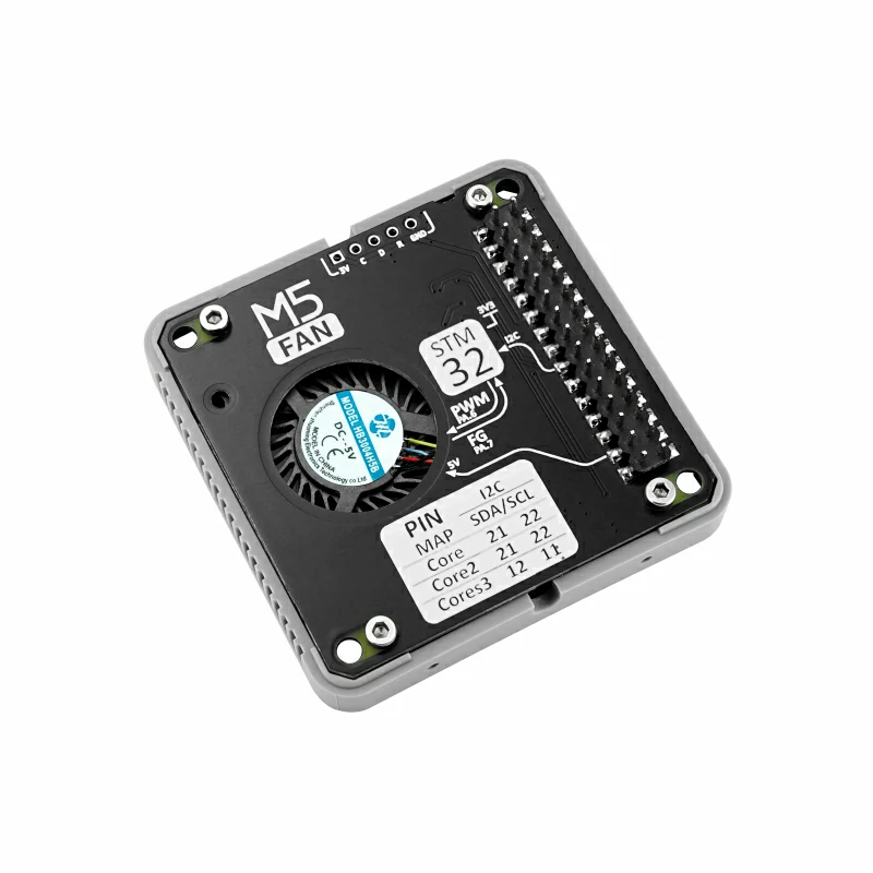
- Required Hardware:

2. Example Program
Example Description
The Module Fan v1.1 is a fan cooling module that uses the I2C communication interface. It supports configuring motor parameters such as PWM frequency, duty cycle, etc., for motor speed control, effectively helping with device cooling. This example will use Module Fan v1.1 with the CoreS3 main control unit to control the fan motor while displaying the status information.
#include <M5Unified.h>
#include <m5_module_fan.hpp>

M5ModuleFan moduleFan;
uint8_t deviceAddr = MODULE_FAN_BASE_ADDR;
uint8_t dutyCycle  = 80;
bool fan_status    = true;
M5Canvas canvas(&M5.Display);

void setup()
{
    M5.begin();
    Serial.begin(115200);
    canvas.createSprite(320, 240);
    canvas.setFont(&fonts::FreeSerifBold12pt7b);
    canvas.setTextDatum(top_center);
    canvas.setTextColor(WHITE);

    while (!moduleFan.begin(&Wire1, deviceAddr, 12, 11, 400000)) {
        Serial.printf("Module FAN Init faile\r\n");
        canvas.drawString("Module FAN Init faile", 160, 120);
        canvas.pushSprite(0, 0);
        delay(1000);
    }

    // Set the fan to rotate at 80% duty cycle
    moduleFan.setPWMDutyCycle(dutyCycle);
    moduleFan.setPWMFrequency(PWM_48KHZ);
    moduleFan.setStatus(MODULE_FAN_ENABLE);
}

void loop()
{
    int pwm_config_index  = moduleFan.getPWMFrequency();
    String pwm_config_str = "";

    switch (pwm_config_index) {
        case PWM_1KHZ:
            pwm_config_str = "1KHz";
            break;
        case PWM_12KHZ:
            pwm_config_str = "12KHz";
            break;
        case PWM_24KHZ:
            pwm_config_str = "24KHz";
            break;
        case PWM_48KHZ:
            pwm_config_str = "48KHz";
            break;
    }
    canvas.setCursor(0, 10);
    canvas.clear();
    canvas.printf("Work Status      : %s\r\n", moduleFan.getStatus() == MODULE_FAN_ENABLE ? "RUNNING" : "STOP");
    canvas.printf("PWM  Frequency   : %s\r\n", pwm_config_str.c_str());
    canvas.printf("PWM  Duty Cycle  : %d\r\n", moduleFan.getPWMDutyCycle());
    canvas.printf("RPM              : %d\r\n", moduleFan.getRPM());
    canvas.pushSprite(0, 0);

    M5.update();
    auto t = M5.Touch.getDetail();
    if (t.wasClicked() || M5.BtnA.wasClicked()) {
        fan_status = !fan_status;
        if (fan_status) {
            moduleFan.setStatus(MODULE_FAN_ENABLE);
        } else {
            moduleFan.setStatus(MODULE_FAN_DISABLE);
        }
    }
}
3. Compile and Upload
- Download Mode: Different devices require a download mode before programming. The steps may vary for different main control units. For detailed instructions, refer to the Arduino IDE Getting Started Tutorial at the bottom of the page to see the device-specific download procedure.
For CoreS3, press and hold the reset button (for about 2 seconds) until the internal green LED lights up, then release it. The device is now in download mode, waiting for programming.
.gif)
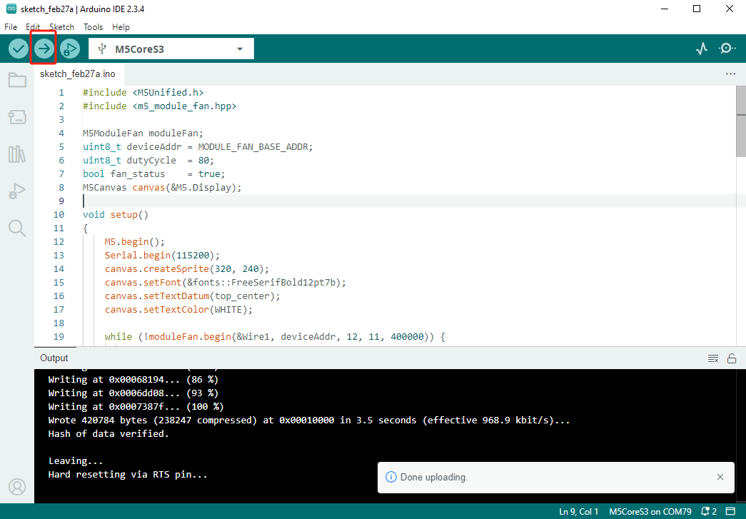
- Select the device port and click the compile and upload button in the upper left corner of the Arduino IDE. Wait for the program to compile and upload to the device.
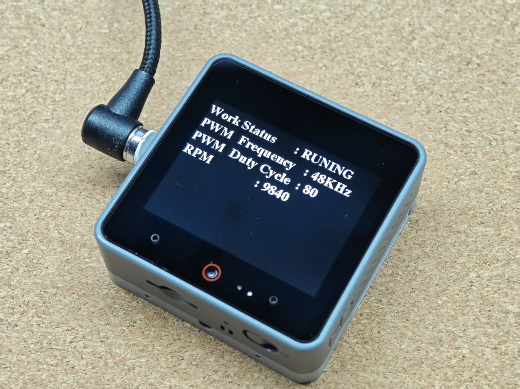
4. Fan Start
Touch the screen to control the fan start and stop, while viewing the current fan speed and configuration information on the screen.
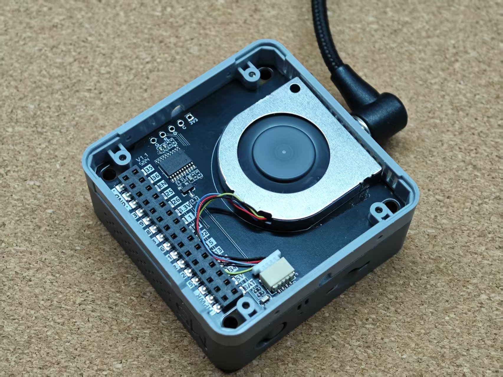
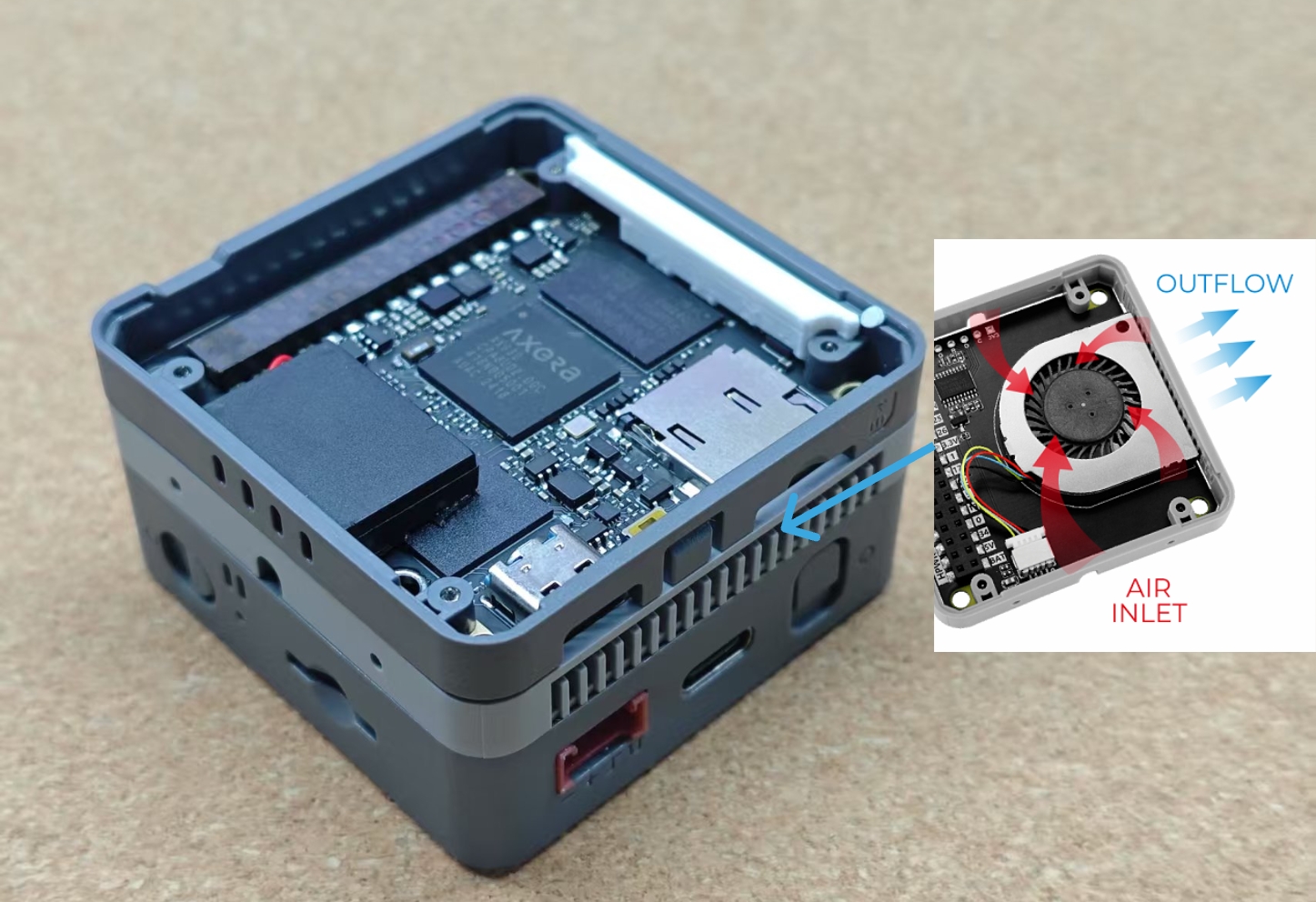
Cooling Module Installation
The intake of Module Fan v1.1 is designed at the bottom of the module. To achieve effective cooling, it is recommended to stack it on top of the module that requires cooling, as shown in the image below.