

Arduino Quick Start
2. Devices & Examples
3. M5Unified
4. M5GFX
5. Extensions
Unit
Atomic
Tab5
IoT
Accessories
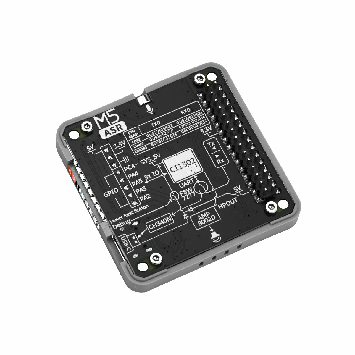
Module ASR Arduino Tutorial
1. Preparation
- Environment setup: Refer to the Arduino IDE Getting Started Guide to complete IDE installation, and install the corresponding board package and required libraries for your development board.
- Required libraries:
- Required hardware:


2. Notes
3. Example
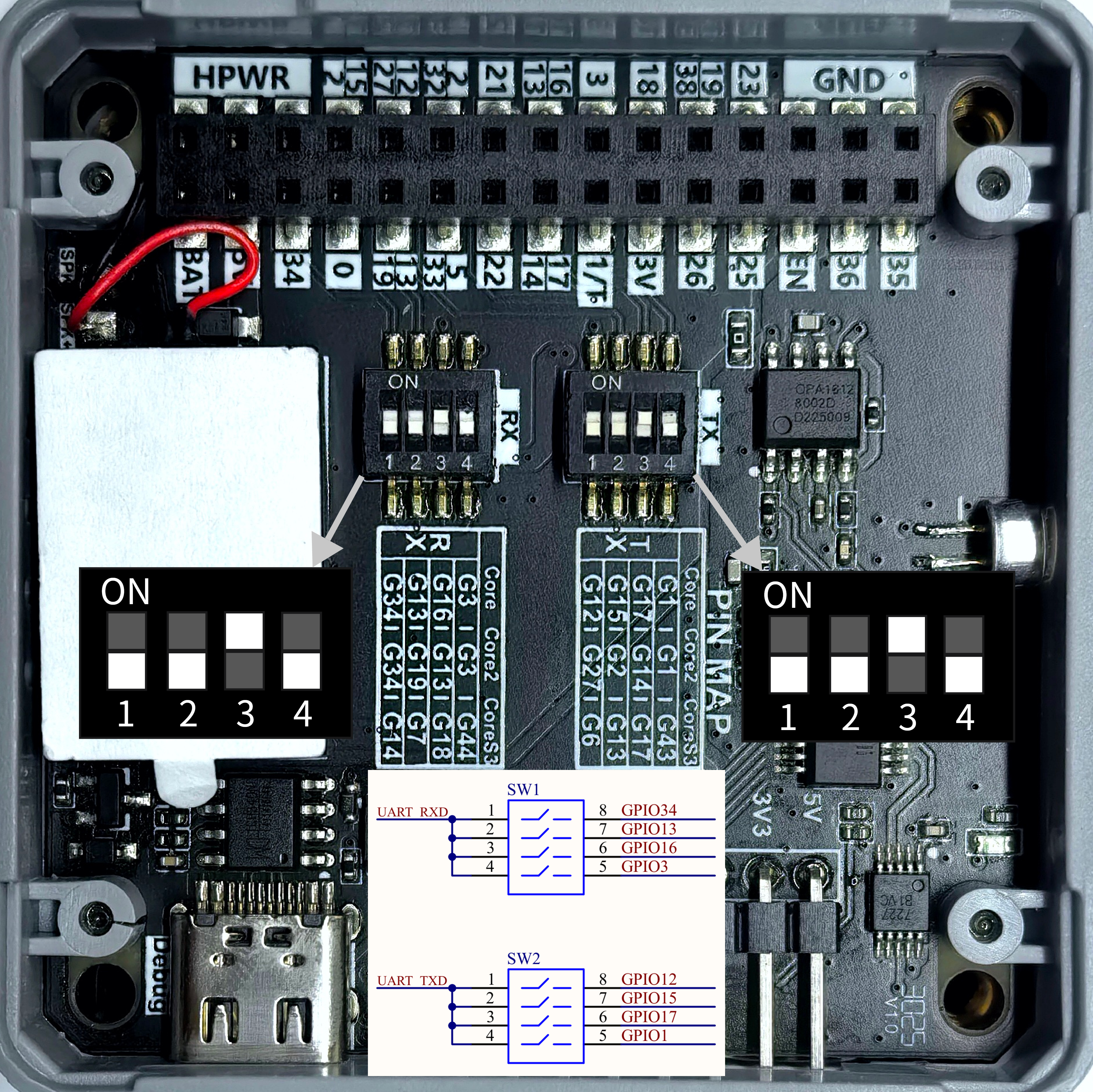
- The main controller used in this tutorial is CoreS3-SE, paired with Module ASR for voice interaction. Before use, please refer to the figure below and set the DIP switches to the specified positions.
3.1 DIP Switches
Module ASR communicates via UART. Modify the pin definitions in the program according to your actual wiring. After connection, the corresponding UART IOs are G18 (RX) and G17 (TX). The DIP switch positions are shown below:
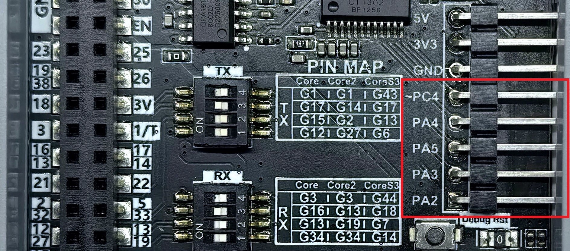
3.2 IO Ports
- Module ASR features 5 IO ports. You can control the output level of each IO via voice commands, or trigger specific voice responses via IO input. The IO ports are shown below:
3.3 Sample Code
Module ASR supports voice and serial wake-up and command input, and returns the current command information via voice and serial. The default firmware includes some preset command words, not limited to those like turn off below. For details, see Module ASR Preset Commands.
#include <M5Unified.h>
#include <unit_asr.hpp>

ASRUnit asr;

void turnOnHandler()
{
    Serial.println("turn on command received!");
    M5.Display.clear();
    M5.Display.drawCenterString("turn off!", 160, 110);
}

void turnOffHandler()
{
    Serial.println("turn off command received!");
    M5.Display.clear();
    M5.Display.drawCenterString("turn off!", 160, 110);
}

void wakeupHandler()
{
    Serial.println("wakeup command received!");
    M5.Display.clear();
    M5.Display.drawCenterString("wakeup!", 160, 110);
}

void PA2_HighHandler()
{
    Serial.println("set PA2 level to high");
    M5.Display.clear(TFT_GREEN);
    M5.Display.drawCenterString("PA2 level: high", 160, 110);
}

void PA2_LowHandler()
{
    Serial.println("set PA2 level to low");
    M5.Display.clear(TFT_YELLOW);
    M5.Display.drawCenterString("PA2 level: low", 160, 110);
}

void AddHandler()
{
    Serial.println("Add command received!");
    M5.Display.clear();
    M5.Display.drawCenterString("Add", 160, 110);
}

void PA4_InputHandler()
{
    Serial.println("PA4 key pressed");
    M5.Display.clear();
    M5.Display.drawCenterString("PA4 key pressed", 160, 110);
}

void setup()
{
    M5.begin();
    M5.Display.setFont(&fonts::FreeMonoBold12pt7b);
    Serial.begin(115200);
    asr.begin(&Serial1, 115200, 18, 17);
    asr.addCommandWord(0x14, "turn on", turnOnHandler);
    asr.addCommandWord(0x15, "turn off", turnOffHandler);
    asr.addCommandWord(0x31, "Hi,ASR", wakeupHandler);
    asr.addCommandWord(0x32, "hello", wakeupHandler);
    asr.addCommandWord(0x50, "PA2 high level", PA2_HighHandler);
    asr.addCommandWord(0x51, "PA2 low level", PA2_LowHandler);
    asr.addCommandWord(0xFF, "Hi,M Five", wakeupHandler);
    asr.addCommandWord(0x33, "Add", AddHandler);
    asr.addCommandWord(0x5B, "PA4 input", PA4_InputHandler);
    asr.printCommandList();
    M5.Display.clear();
    M5.Display.drawCenterString("Say", 160, 60);
    M5.Display.drawCenterString("\"Hi,M Five\"", 160, 80);
    M5.Display.drawCenterString("\"Hello\"", 160, 100);
    M5.Display.drawCenterString("\"Hi,ASR\"", 160, 120);
    M5.Display.drawCenterString("to wakeup!", 160, 140);
}

void loop()
{
    M5.update();
    if (asr.update()) {
        Serial.println(asr.getCurrentCommandWord());
        Serial.printf("0x%X\n", asr.getCurrentCommandNum());
        Serial.println(asr.getCurrentRawMessage());
        Serial.println((asr.checkCurrentCommandHandler()));
    }
}3.4 Custom Command Setup
Module ASR can only modify or add new interactive commands by regenerating and flashing custom firmware. Please refer to the Module ASR Custom Firmware Generation and Flashing tutorial for details.
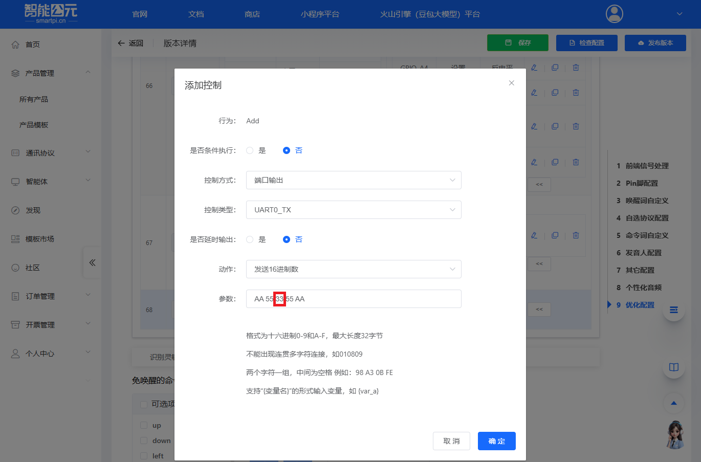
In the above example, the custom voice command
Adduses the frameAA 55 33 55 AA, where the command code is0x33. The firmware configuration is shown below. The example uses theaddCommandWordfunction to add the command to the table and register the callback.
- In the above example,
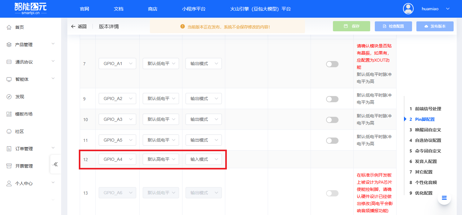
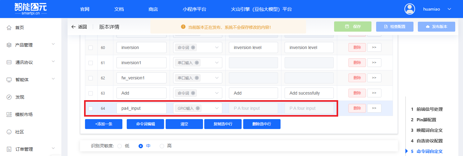
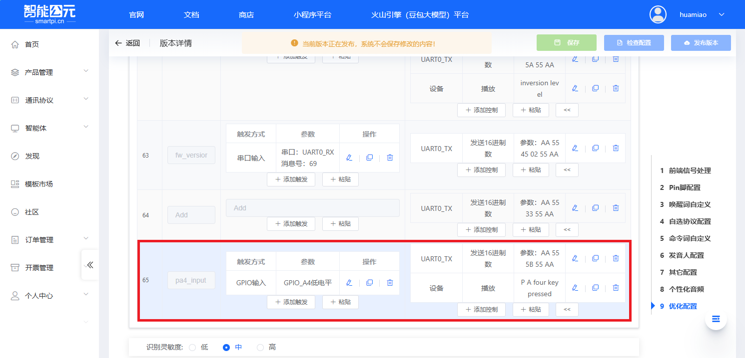
PA4 inputis a custom command, with frameAA 55 5B 55 AAand command code0x5B. The firmware configuration requires settingGPIO_A4to input mode in the pin configuration. Details are shown below. The example uses theaddCommandWordfunction to add the command to the table and register the callback.
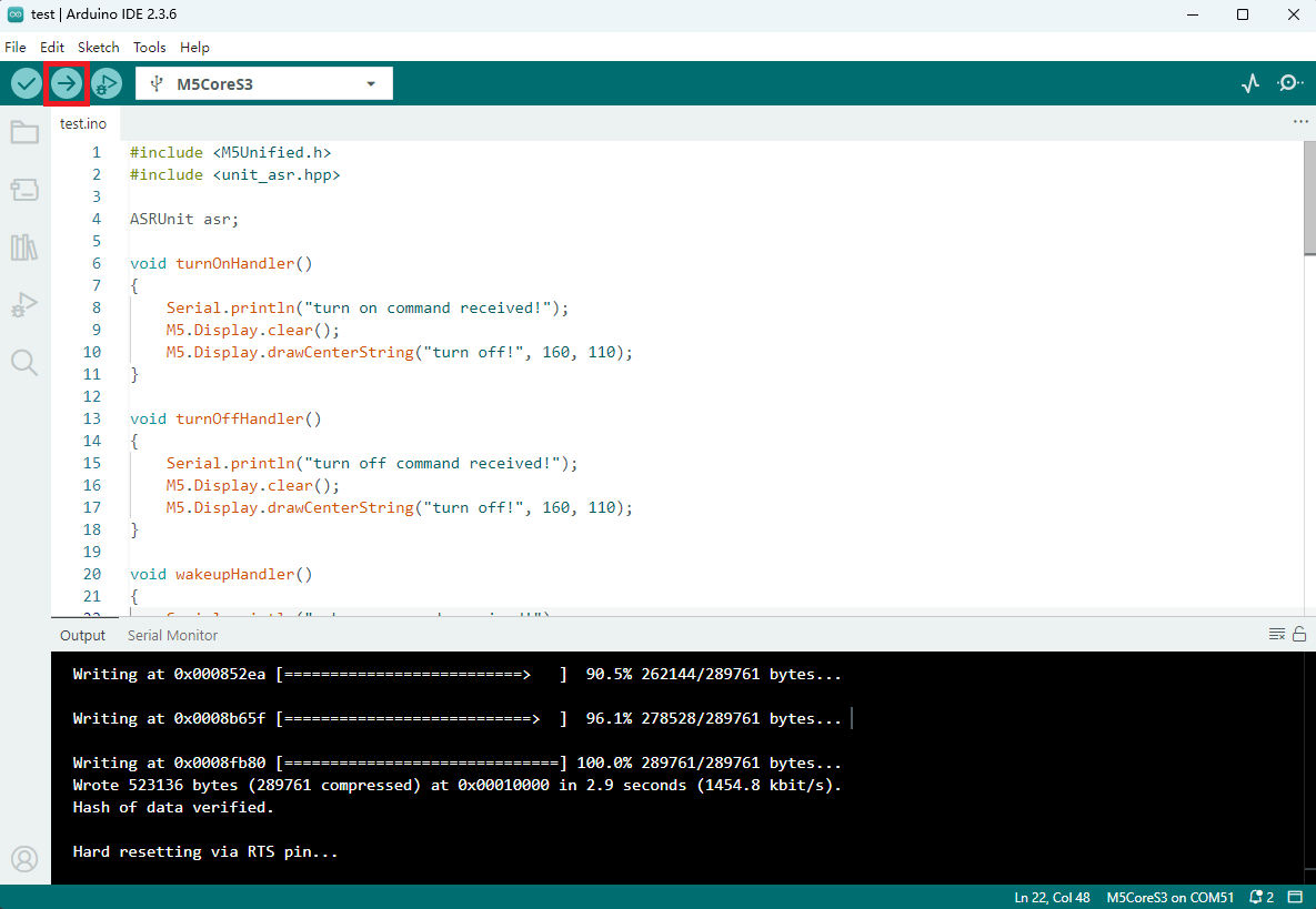
4. Compile & Upload
- Enter download mode: On CoreS3-SE, press and hold the reset button (about 2 seconds) until the internal green LED lights up, then release. The device is now in download mode and ready for flashing.
- Select the device port, click the compile/upload button in the upper left of the Arduino IDE, and wait for the program to finish compiling and uploading.
5. Command Interaction
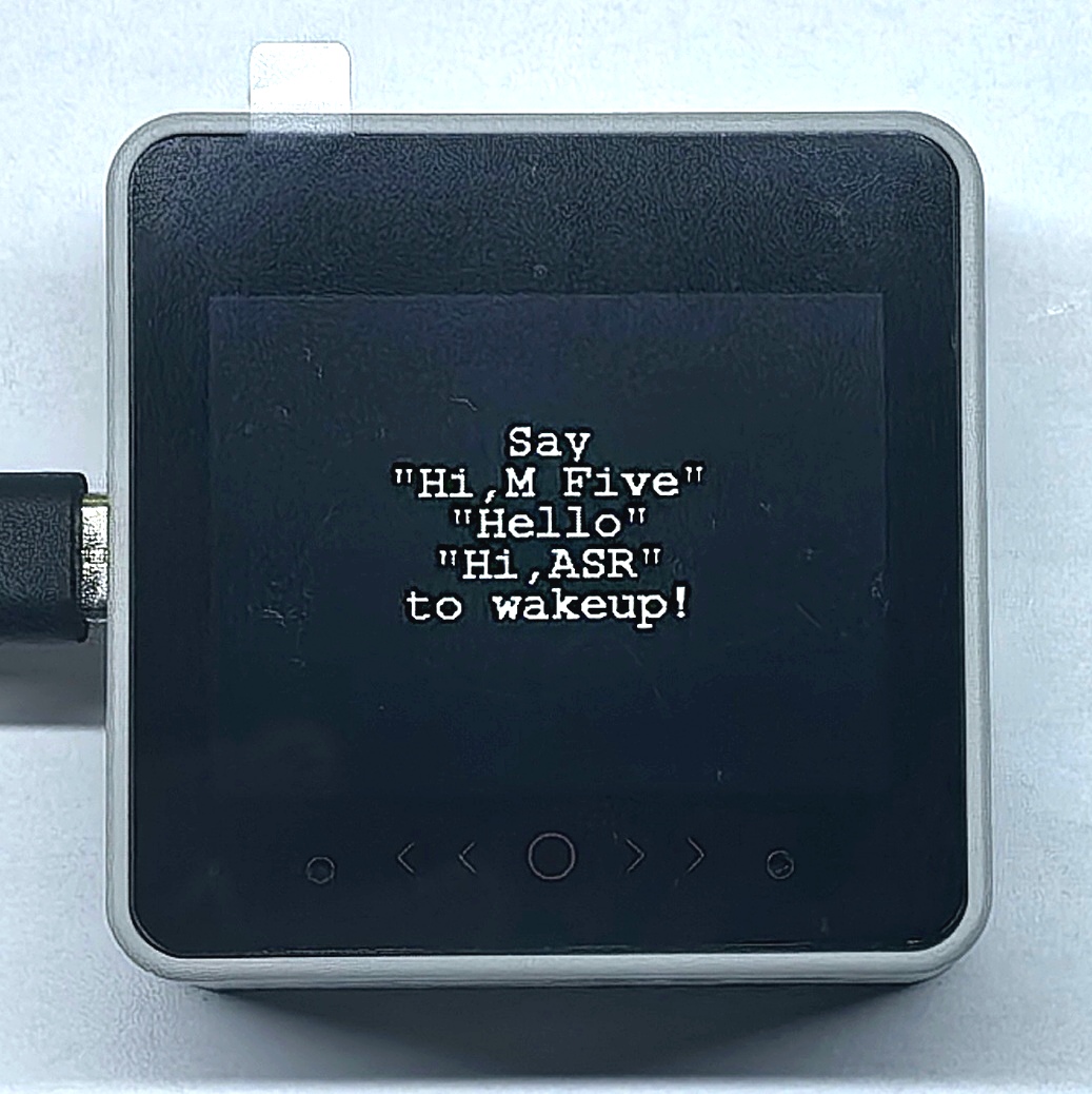
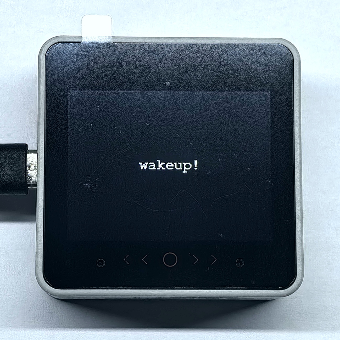
- Wake-up operation
After power-on, the host display shows as in the left image below. Use the voice commandHi M Fiveto wake up the module, which responds withI'm here, and the host display shows as in the right image below.
Serial monitor output:
wakeup command received!
Hi,M Five
0xFF
0xAA 0x55 0xFF 0x55 0xAA
1- Preset command interaction
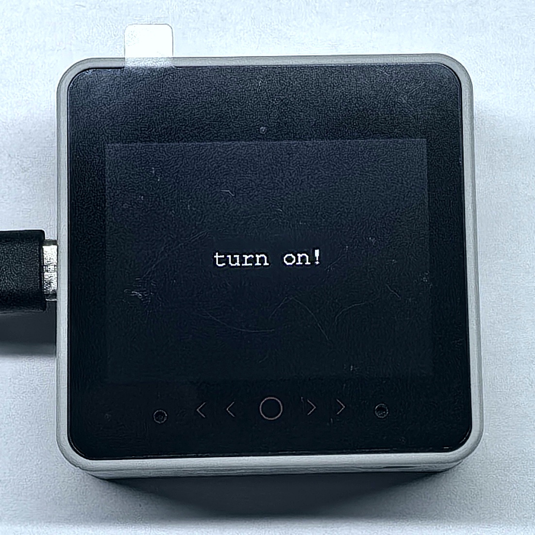
- Use the voice command
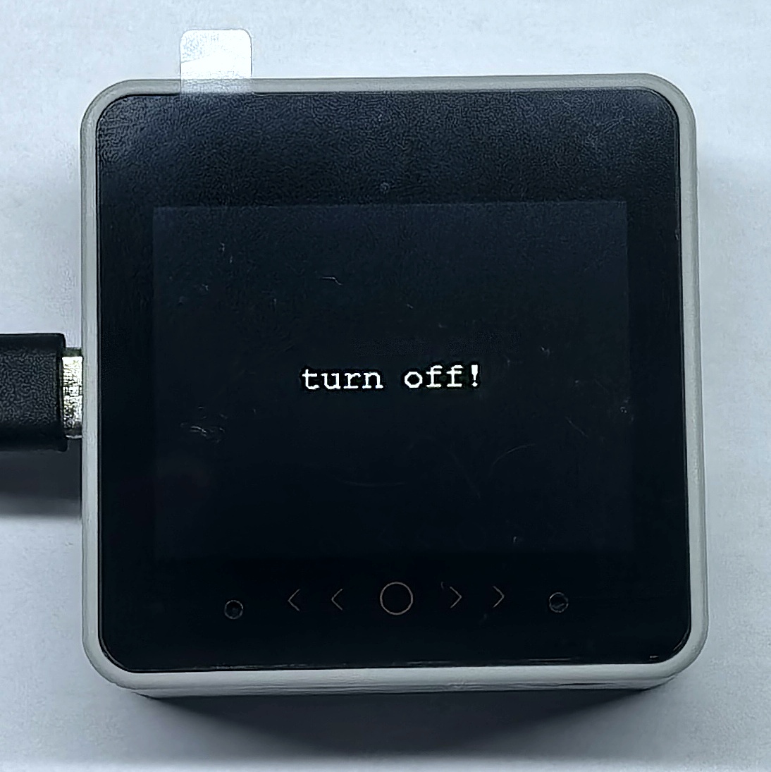
Turn on, the module repliesOK, and the host display showsturn on!. - Use the voice command
Turn off, the module repliesOK, and the host display showsturn off!.
- Use the voice command
Serial monitor output:
turn on command received!
turn on
0x46
0xAA 0x55 0x14 0x55 0xAA
1
turn on command received!
turn on
0x46
0xAA 0x55 0x15 0x55 0xAA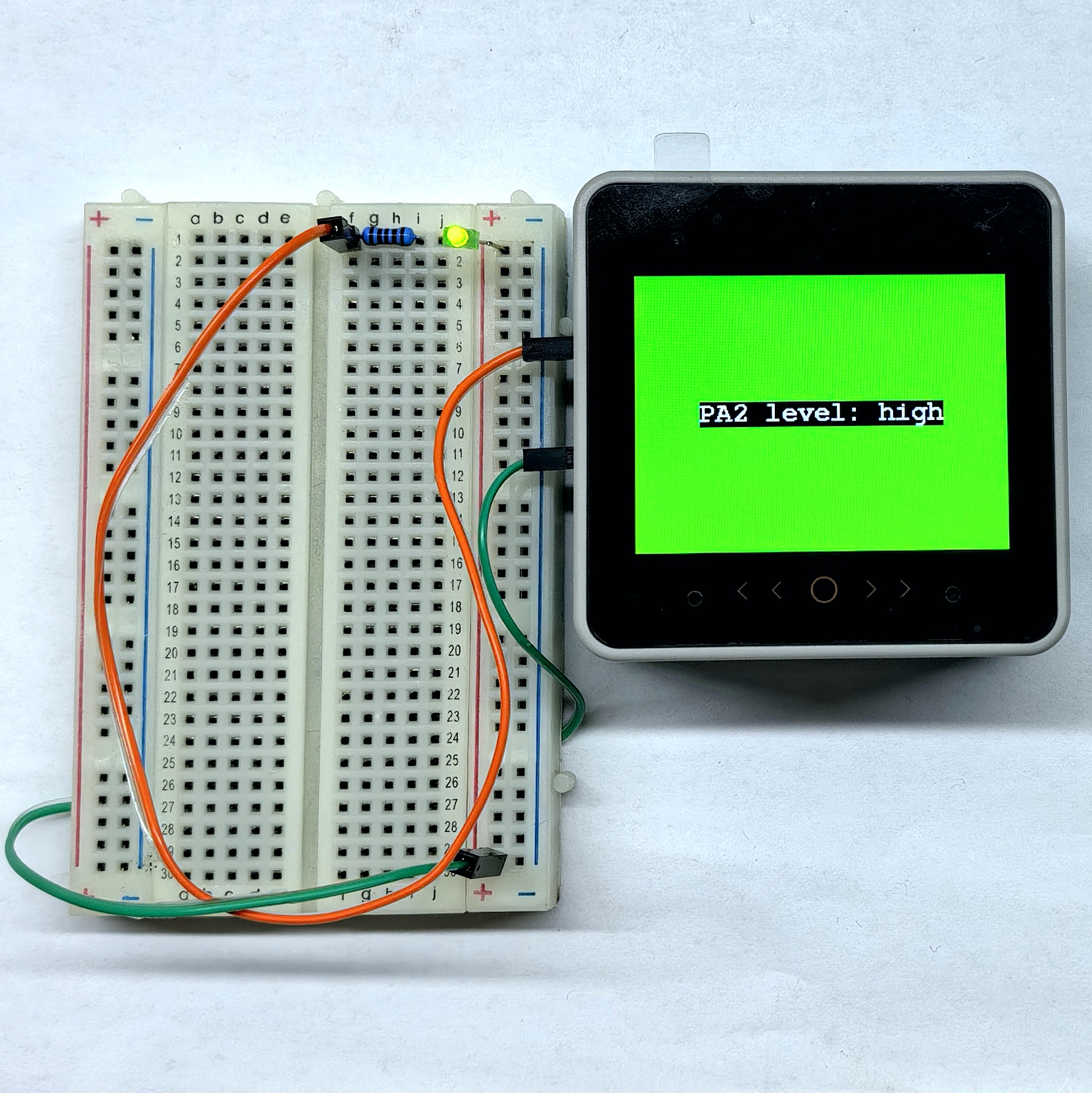
1- IO control command interaction
- Use the voice command
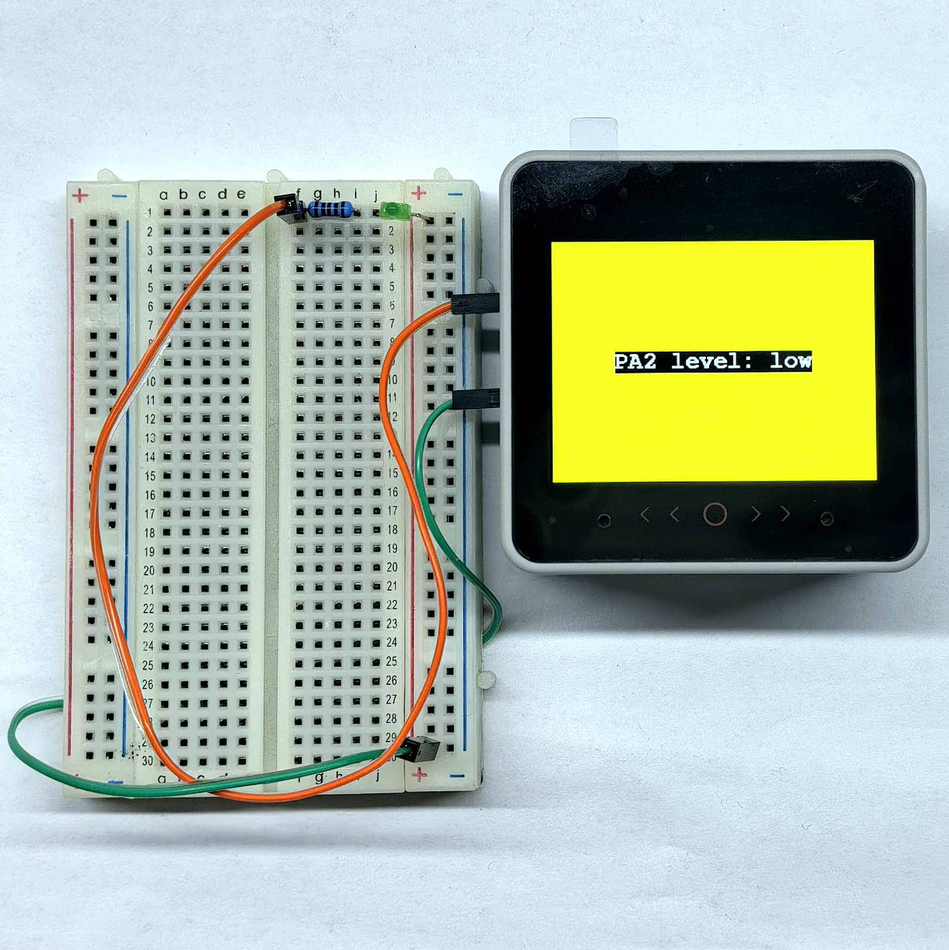
PA2 high level, the module repliesPA2 high level, the host display showsPA2 level: highand the background turns green, PA2 outputs high. - Use the voice command
PA2 low level, the module repliesPA2 low level, the host display showsPA2 level: lowand the background turns yellow, PA2 outputs low. - Press the B key (red button) on the Unit Dual Button, the module replies
PA4 key pressed, and the host display showsPA4 key pressed.
- Use the voice command
Serial monitor output:
set PA2 level to high
PA2 high level
0x50
0xAA 0x55 0x50 0x55 0xAA
1
set PA2 level to low
PA2 low level
0x51
0xAA 0x55 0x51 0x55 0xAA
1
PA4 key pressed
PA4 input
0x5B
0xAA 0x55 0x5B 0x55 0xAA
1- Custom command interaction
Use the voice commandAdd, the module repliesAdd successfully, and the host display showsAdd successfully!.

Serial monitor output:
Add command received!
Add
0x33
0xAA 0x55 0x33 0x55 0xAA
1