

Arduino Quick Start
2. Devices & Examples
3. M5Unified
4. M5GFX
5. Extensions
Unit
Atomic
Tab5
IoT
Accessories
Unit 8Angle Arduino User Guide
1. Preparations
- Environment Setup: Refer to the Arduino IDE Getting Started Tutorial to complete the IDE installation, and install the corresponding board manager and required driver libraries according to your development board.
- Driver Libraries Used:
- Hardware Products Used:

2. Example
Example Explanation
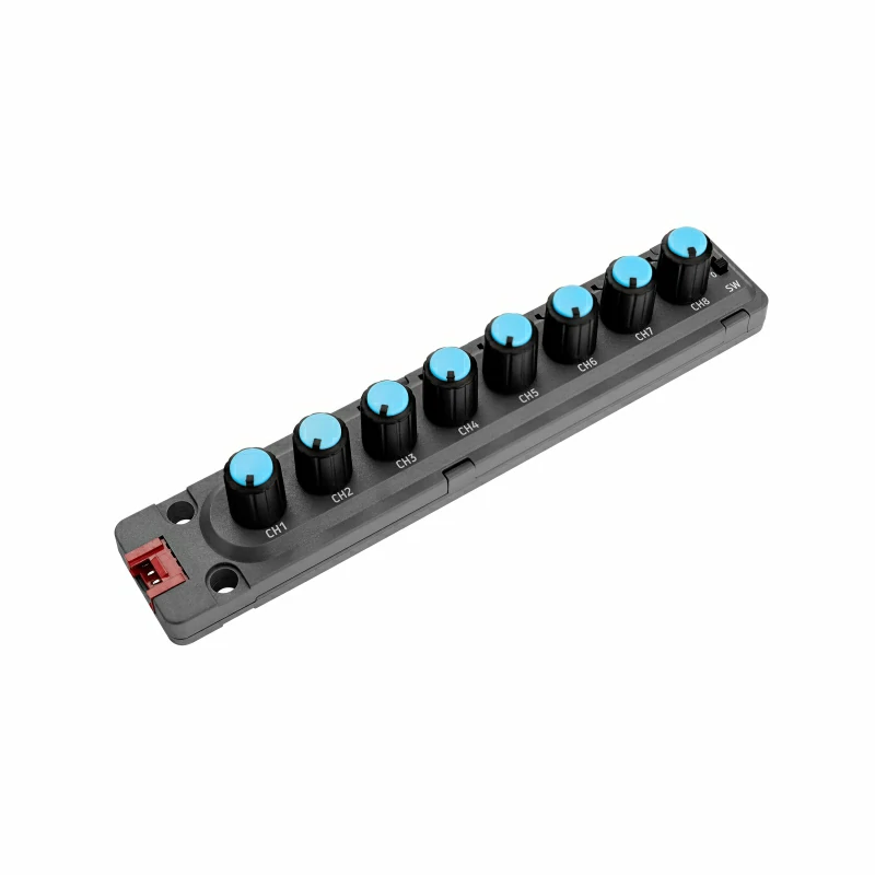
Unit 8Angle is an input unit that integrates 8 adjustable potentiometers, along with 9 programmable RGB LEDs and a toggle switch. In this example, we use the CoreS3 main controller via its PORT.A expansion interface to read the input status of each potentiometer channel and the status of the toggle switch, while also controlling the RGB LEDs.
cpp
1 2 3 4 5 6 7 8 9 10 11 12 13 14 15 16 17 18 19 20 21 22 23 24 25 26 27 28 29 30 31 32 33 34 35 36 37 38 39
#include <M5Unified.h>
#include "M5_ANGLE8.h"

M5_ANGLE8 dev;
uint32_t color_list[]   = {0xff0000, 0x00ff00, 0x0000ff};
uint8_t color_index     = 0;
time_t last_update_time = 0;

void setup()
{
    M5.begin();
    Serial.begin(115200);
    M5.Display.setFont(&fonts::lgfxJapanMinchoP_20);
    Wire.begin(2, 1, 100000L);
    while (!dev.begin(ANGLE8_I2C_ADDR)) {
        M5.Display.drawString("Unit 8Angle init Fail!", M5.Display.width() / 2, M5.Display.height() / 2);
        delay(1000);
    }
}

void loop()
{
    bool switch_status = dev.getDigitalInput();
    M5.Display.clear();
    M5.Display.setCursor(0, 0);
    M5.Display.printf("Switch: %s\r\n", switch_status ? "ON" : "OFF");
    for (uint8_t i = 0; i < ANGLE8_TOTAL_ADC; i++) {
        uint16_t adc_v = dev.getAnalogInput(i, _12bit);
        M5.Display.printf("CH[%d]: %d\r\n", i, adc_v);
    }
    if (millis() - last_update_time > 1000) {
        color_index = (color_index + 1) % 3;
        for (uint8_t i = 0; i < ANGLE8_TOTAL_LED; i++) {
            dev.setLEDColor(i, color_list[color_index], 80);
        }
        last_update_time = millis();
    }
    delay(100);
}3. Compile and Upload
- Download Mode: Different devices require a download mode before flashing the program, and this step may vary depending on the main controller. For details, please refer to the device programming download tutorial list at the bottom of the Arduino IDE Getting Started Tutorial page for specific instructions.
For the CoreS3, press and hold the reset button (approximately 2 seconds) until the internal green LED lights up, then release the button. At this point, the device will enter download mode and wait for flashing.
.gif)
- Select the device port, click the compile and upload button in the upper left corner of the Arduino IDE, and wait for the program to compile and upload to the device.
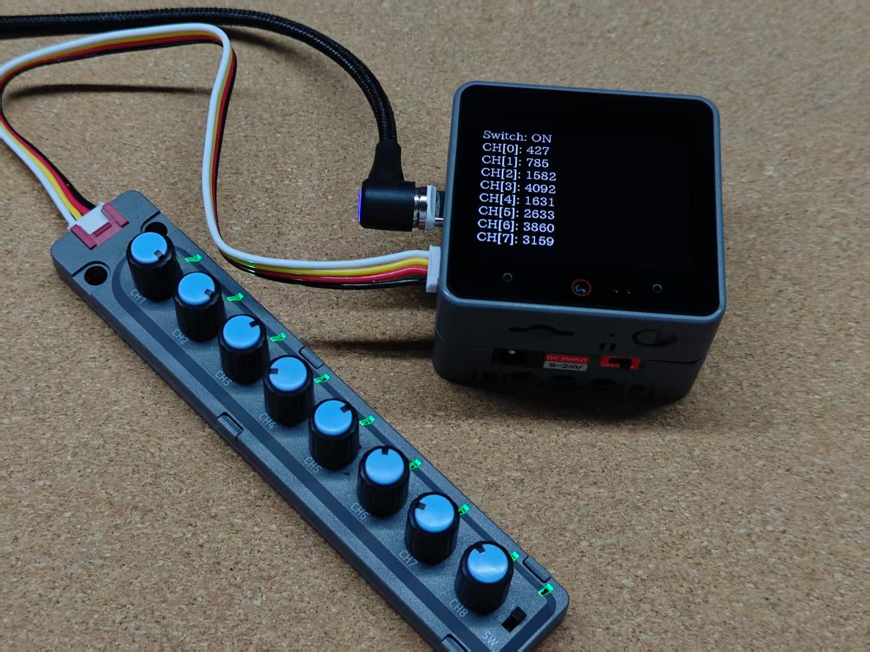
4. Reading Knob Status
Read and display the statuses of the potentiometers and the switch, while also controlling the RGB LED color to change every 1 second.
Page Tools