Arduino Quick Start
2. Devices & Examples
3. M5Unified
4. M5GFX
5. Extensions
Unit
Atomic
Tab5
IoT
Accessories
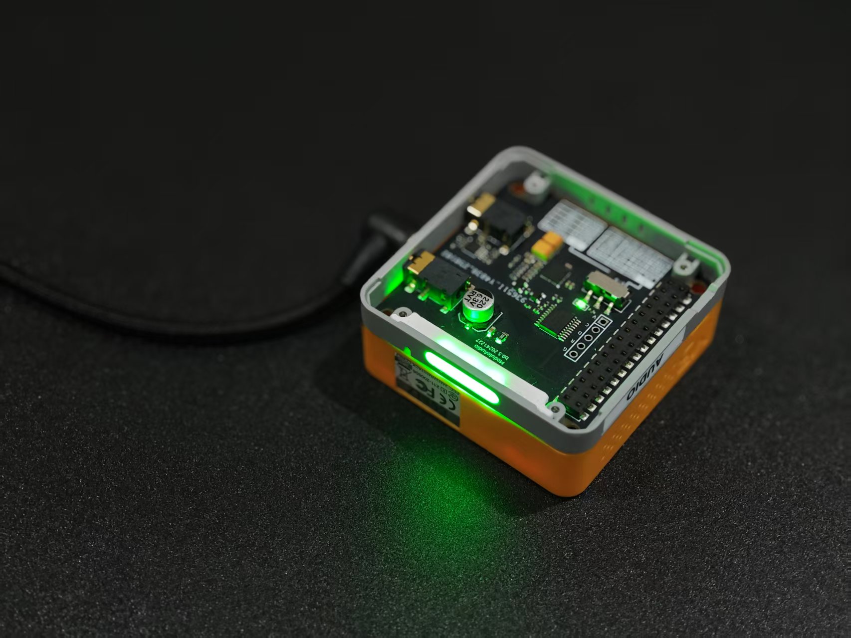
Module Audio Arduino Tutorial
1. Prerequisites
1. Environment Setup: Refer to the Arduino IDE Getting Started Guide to install the IDE, then install the board package and driver libraries required for your controller.
2. Required Driver Libraries:
3. Required Hardware:

2. Initialization
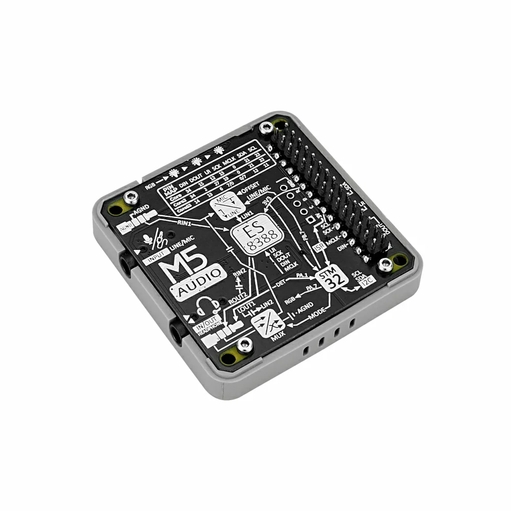
Module Audio integrates an STM32 controller for headset interface standard switching, LED control, headphone insertion detection (channel 2 only), microphone input mode configuration, and other functions.
audio.setHPMode(AUDIO_HPMODE_NATIONAL); to select the appropriate standard for compatibility: OMTP (AUDIO_HPMODE_NATIONAL) or CTIA (AUDIO_HPMODE_AMERICAN).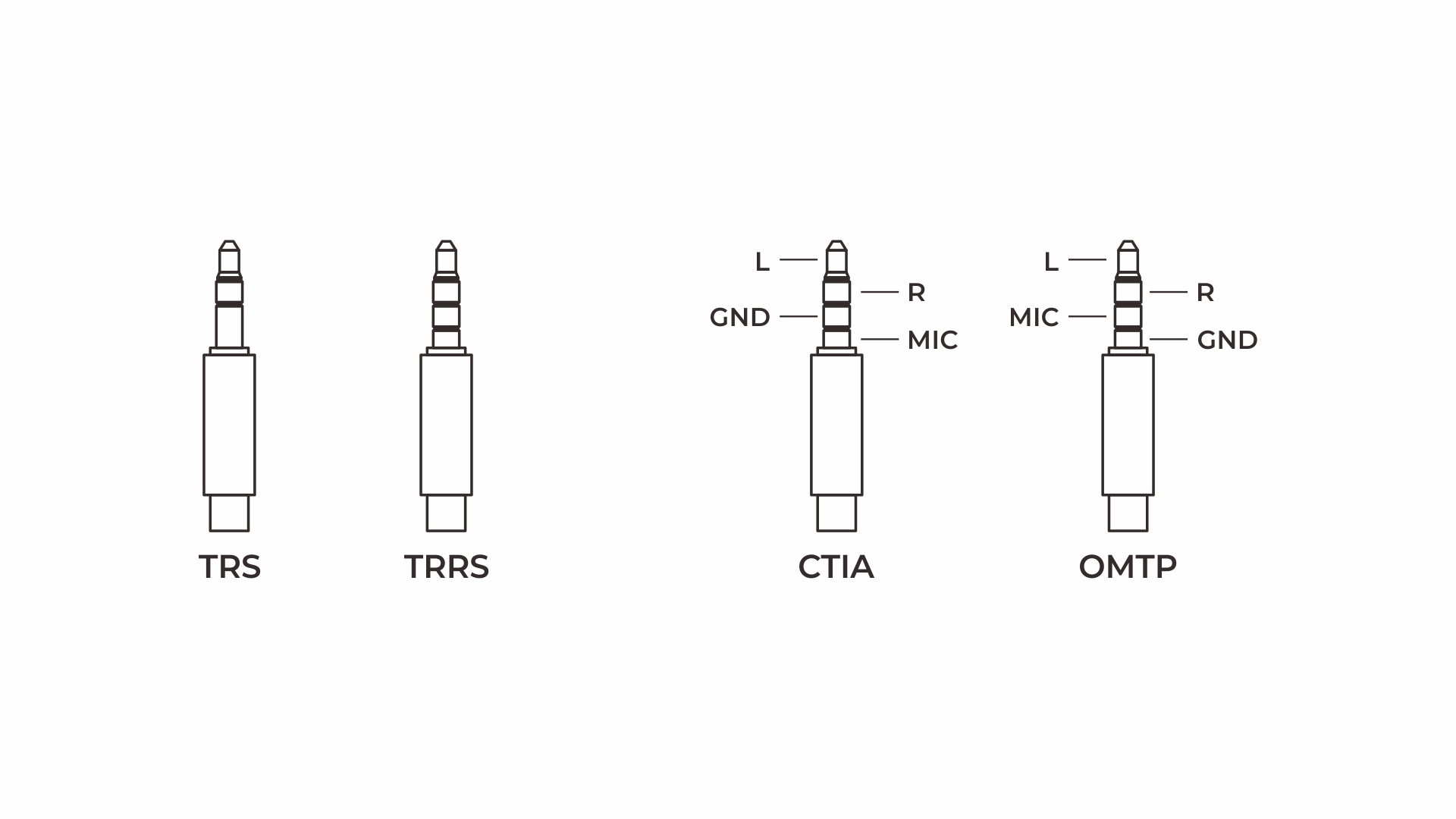
#include <M5Unified.h>
#include <M5Module_Audio.h>

M5ModuleAudio audio;

void setup()
{
    // Initialize M5Unified without the built-in audio devices.
    auto cfg = M5.config();
    cfg.serial_baudrate = 115200;
    cfg.internal_mic = false;
    cfg.internal_spk = false;

    M5.begin(cfg);

    if (!audio.begin(Wire)) {
        Serial.println("Module Audio not found.");

        while (true) {
            delay(1000);
        }
    }

    audio.setHPMode(AUDIO_HPMODE_NATIONAL);
    // audio.setHPMode(AUDIO_HPMODE_AMERICAN);
    audio.setMICStatus(AUDIO_MIC_OPEN);
    audio.setRGBBrightness(100);

    for (uint8_t i = 0; i < 3; ++i) {
        audio.setRGBLED(i, 0x0000FF);
    }
}

void loop()
{
    M5.update();

    bool is_hp_inserted = audio.getHPInsertStatus();

    if (is_hp_inserted) {
        Serial.println("Headphone Inserted");
    } else {
        Serial.println("Headphone Removed");
    }
    delay(500);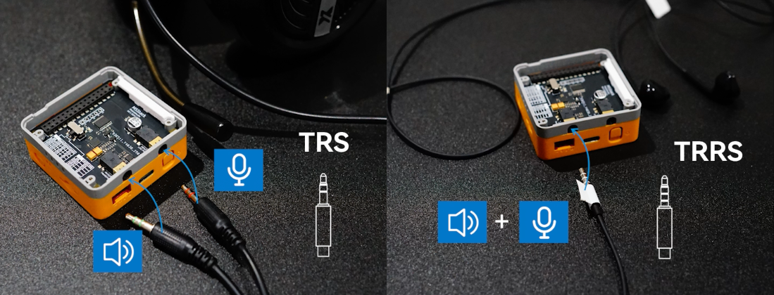
}3. Input Interface Configuration
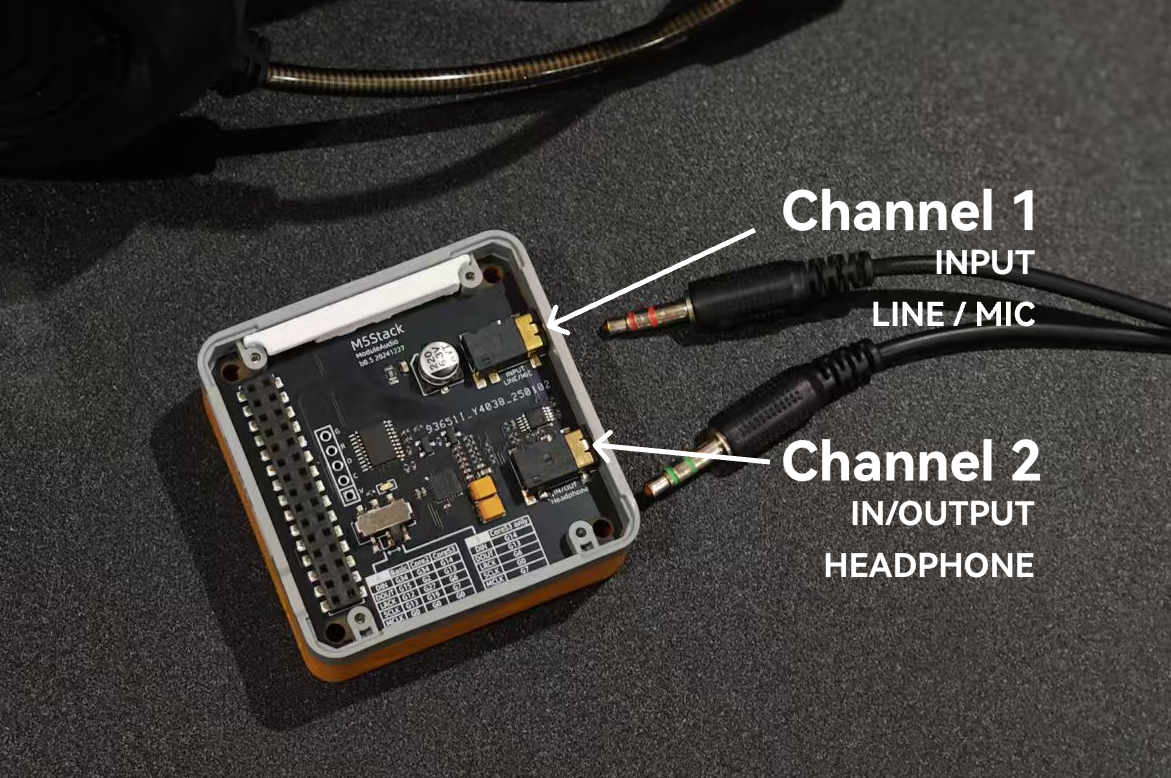
- TRS audio wiring: Connect the MIC input to channel 1 and the audio output to channel 2. This configuration is suitable for devices with separate microphone and audio plugs, such as PC headsets.
- TRRS combined audio wiring: Connect the combined audio input/output device to channel 2. This configuration supports wired headsets with microphones and is also compatible with TRS audio devices.
After initialization, call the following APIs to configure the input/output channels, volume, gain, and other parameters.
// Use input 1 for both channels.
audio.setMicInputLine(ADC_INPUT_LINPUT1_RINPUT1);

// Use input 2 for both channels.
// audio.setMicInputLine(ADC_INPUT_LINPUT2_RINPUT2);

audio.setSpeakerOutput(DAC_OUTPUT_OUT1);
audio.setMicAdcVolume(100);
audio.setSpeakerVolume(40);
audio.setMicGain(MIC_GAIN_24DB);
audio.setBitsSample(ES_MODULE_ADC, BIT_LENGTH_16BITS);
audio.setSampleRate(SAMPLE_RATE_44K);4. Recording and Playback
Using the TRS wiring configuration, connect the MIC input to channel 1 and the audio output to channel 2 to capture and play microphone data in real time.
#include <M5Unified.h>
#include <M5Module_Audio.h>

M5ModuleAudio audio;

static constexpr size_t AUDIO_BUFFER_SIZE = 512;

static uint8_t audio_buffer[AUDIO_BUFFER_SIZE];

void setup()
{
    // Initialize M5Unified without the built-in audio devices.
    auto cfg = M5.config();
    cfg.serial_baudrate = 115200;
    cfg.internal_mic = false;
    cfg.internal_spk = false;

    M5.begin(cfg);

    // Initialize Module Audio on the internal I2C bus.
    if (!audio.begin(M5.In_I2C)) {
        Serial.println("Module Audio not found.");

        while (true) {
            delay(1000);
        }
    }

    // Configure the Module Audio controller.
    audio.setHPMode(AUDIO_HPMODE_NATIONAL);
    audio.setMICStatus(AUDIO_MIC_OPEN);
    audio.setRGBBrightness(100);

    Serial.printf("HP mode: %d\n", audio.getHPMode());
    Serial.printf("MIC status: %d\n", audio.getMICStatus());

    // Set the status LEDs.
    const uint32_t colors[] = {
        0x00FF00,
        0xFFFF00,
        0xFFFFFF,
    };

    for (uint8_t i = 0; i < 3; ++i) {
        audio.setRGBLED(i, colors[i]);

        Serial.printf(
            "RGB-%u: set=%06X, read=%06X\n",
            i,
            static_cast<unsigned>(colors[i]),
            static_cast<unsigned>(audio.getRGBLED(i)));
    }

    // Configure ES8388 for microphone loopback.
    audio.setMicInputLine(ADC_INPUT_LINPUT2_RINPUT2);
    audio.setMicGain(MIC_GAIN_24DB);
    audio.setMicAdcVolume(100);
    audio.setSpeakerVolume(40);
    audio.setSpeakerOutput(DAC_OUTPUT_OUT1);
    audio.setBitsSample(
        ES_MODULE_ADC_DAC,
        BIT_LENGTH_16BITS);
    audio.setSampleRate(SAMPLE_RATE_44K);

    // Print the ES8388 register values.
    Serial.println("Read ES8388 registers:");

    uint8_t* registers = audio.readAllReg();

    if (registers != nullptr) {
        for (uint8_t i = 0; i < 53; ++i) {
            Serial.printf(
                "Reg-%02u = 0x%02X\r\n",
                i,
                registers[i]);
        }
    }

    Serial.println("Audio loopback started.");
}

void loop()
{
    M5.update();

    // Capture one audio buffer.
    if (!audio.record(audio_buffer, sizeof(audio_buffer))) {
        Serial.println("Audio record failed.");
        delay(100);
        return;
    }

    // Play the captured audio buffer.
    if (!audio.play(audio_buffer, sizeof(audio_buffer))) {
        Serial.println("Audio playback failed.");
        delay(100);
    }
}5. Playing a WAV File from microSD
Configure channel 2 as the audio output, load a WAV file stored on the microSD card, and play it. Before use, place the WAV file on the microSD card and insert the card into the controller's card slot.
#include <M5Unified.h>
#include <M5Module_Audio.h>
#include <SPI.h>
#include <SD.h>

M5ModuleAudio audio;
File wav_file;

static constexpr char WAV_PATH[] = "/hello.wav";
static constexpr size_t WAV_HEADER_SIZE = 44;
static constexpr size_t AUDIO_BUFFER_SIZE = 1024;

static uint8_t audio_buffer[AUDIO_BUFFER_SIZE];

bool openWavFile()
{
    if (wav_file) {
        wav_file.close();
    }

    wav_file = SD.open(WAV_PATH, FILE_READ);

    if (!wav_file) {
        Serial.printf("Failed to open %s\n", WAV_PATH);
        return false;
    }

    if (wav_file.size() <= WAV_HEADER_SIZE) {
        Serial.println("Invalid or empty WAV file.");
        wav_file.close();
        return false;
    }

    Serial.printf(
        "WAV file size: %u bytes\n",
        static_cast<unsigned>(wav_file.size()));

    if (!wav_file.seek(WAV_HEADER_SIZE)) {
        Serial.println("Failed to skip WAV header.");
        wav_file.close();
        return false;
    }

    return true;
}

void setup()
{
    auto cfg = M5.config();
    cfg.serial_baudrate = 115200;
    cfg.internal_mic = false;
    cfg.internal_spk = false;

    M5.begin(cfg);

    Serial.printf(
        "Detected board: %d\n",
        static_cast<int>(M5.getBoard()));

    if (!audio.begin(M5.In_I2C)) {
        Serial.println("Module Audio not found.");

        while (true) {
            delay(1000);
        }
    }

    audio.setHPMode(AUDIO_HPMODE_NATIONAL);
    audio.setMICStatus(AUDIO_MIC_OPEN);
    audio.setRGBBrightness(100);

    Serial.printf("HP mode: %d\n", audio.getHPMode());
    Serial.printf("MIC status: %d\n", audio.getMICStatus());

    const uint32_t colors[] = {
        0x00FF00,
        0xFFFF00,
        0xFFFFFF,
    };

    for (uint8_t i = 0; i < 3; ++i) {
        audio.setRGBLED(i, colors[i]);

        Serial.printf(
            "RGB-%u: set=%06X, read=%06X\n",
            i,
            static_cast<unsigned>(colors[i]),
            static_cast<unsigned>(audio.getRGBLED(i)));
    }

    // M5ModuleAudio has already initialized ES8388.
    audio.setMicAdcVolume(100);
    audio.setSpeakerVolume(80);
    audio.setSpeakerOutput(DAC_OUTPUT_OUT1);
    audio.setBitsSample(
        ES_MODULE_ADC_DAC,
        BIT_LENGTH_16BITS);
    audio.setSampleRate(SAMPLE_RATE_44K);

    Serial.println("Read ES8388 registers:");

    uint8_t* registers = audio.readAllReg();

    if (registers != nullptr) {
        for (uint8_t i = 0; i < 53; ++i) {
            Serial.printf(
                "Reg-%02u = 0x%02X\r\n",
                i,
                registers[i]);
        }
    }

    // Get the SD SPI pins for the detected board.
    int sd_sclk = M5.getPin(m5::pin_name_t::sd_spi_sclk);
    int sd_miso = M5.getPin(m5::pin_name_t::sd_spi_miso);
    int sd_mosi = M5.getPin(m5::pin_name_t::sd_spi_mosi);
    int sd_cs   = M5.getPin(m5::pin_name_t::sd_spi_cs);

    Serial.printf("SD SPI: SCLK=%d, MISO=%d, MOSI=%d, CS=%d\n", sd_sclk, sd_miso, sd_mosi, sd_cs);

    SPI.begin(sd_sclk, sd_miso, sd_mosi, sd_cs);

    if (!SD.begin(sd_cs, SPI, 25000000)) {
        Serial.println("Failed to initialize SD card.");

        while (true) {
            delay(1000);
        }
    }

    Serial.println("SD card initialized successfully.");

    if (!openWavFile()) {
        while (true) {
            delay(1000);
        }
    }

    Serial.println("WAV playback started.");
}

void loop()
{
    M5.update();

    if (!wav_file) {
        delay(100);
        return;
    }

    // Restart playback at the beginning of the audio data.
    if (wav_file.available() == 0) {
        if (!wav_file.seek(WAV_HEADER_SIZE)) {
            Serial.println("Failed to restart WAV file.");
            delay(100);
        }

        return;
    }

    size_t bytes_read =
        wav_file.read(audio_buffer, sizeof(audio_buffer));

    if (bytes_read == 0) {
        return;
    }

    if (!audio.play(audio_buffer, bytes_read)) {
        Serial.println("I2S write failed.");
        delay(100);
    }
}6. RGB LED Control
Module Audio integrates three programmable RGB LEDs on its side. Use the following example to control them.
#include <M5Unified.h>
#include <M5Module_Audio.h>

M5ModuleAudio audio;

void setup()
{
    auto cfg = M5.config();
    cfg.serial_baudrate = 115200;
    cfg.internal_mic = false;
    cfg.internal_spk = false;

    M5.begin(cfg);

    if (!audio.begin(M5.In_I2C)) {
        Serial.println("Module Audio not found.");

        while (true) {
            delay(1000);
        }
    }

    audio.setRGBBrightness(100);
    Serial.println("Module Audio initialized successfully.");
}

void loop()
{
    M5.update();

    // Cycle all LEDs through red, green, and blue.
    for (uint8_t i = 0; i < 3; ++i) {
        audio.setRGBLED(i, 0xFF0000);
    }

    delay(1000);

    for (uint8_t i = 0; i < 3; ++i) {
        audio.setRGBLED(i, 0x00FF00);
    }

    delay(1000);

    for (uint8_t i = 0; i < 3; ++i) {
        audio.setRGBLED(i, 0x0000FF);
    }

    delay(1000);
}