

Arduino Quick Start
2. Devices & Examples
3. M5Unified
4. M5GFX
5. Extensions
Unit
Atomic
Tab5
IoT
Accessories
Unit ByteSwitch Arduino Tutorial
1. Preparations
- Environment configuration: Refer to the Arduino IDE Quick Start Guide to install the IDE, and install the corresponding board manager and required driver libraries according to the development board you are using.
- Driver Libraries Used:
Driver Libraries
Unit ByteSwitch is designed very similarly to Unit ByteButton, so we will reuse the M5Unit-ByteButton library for driving.
- Hardware Products Used:

2. Example
Example Explanation
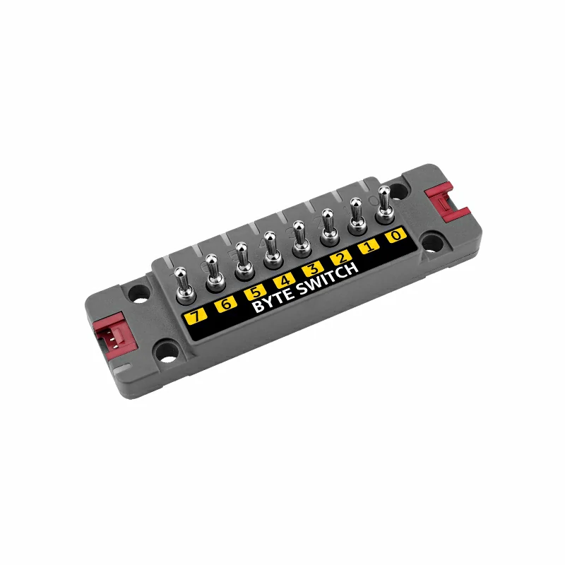
Unit ByteSwitch provides 8 toggle switch inputs and 9 programmable RGB LEDs, suitable for multi-switch input applications. The RGB LEDs support two operating modes: Automatic Mode (configurable such that the toggle switch in different states corresponds to specific RGB LED colors for synchronized lighting) and User-Defined Mode (user manually controls the current LED color display).
Reading Input
cpp
1 2 3 4 5 6 7 8 9 10 11 12 13 14 15 16 17 18 19 20 21 22 23 24 25 26 27 28 29 30 31 32 33 34 35 36 37 38 39 40 41 42
#include <M5Unified.h>
#include "unit_byte.hpp"

uint32_t color_list[]   = {0xff0000, 0x00ff00, 0x0000ff};
uint8_t color_index     = 0;
time_t last_update_time = 0;
uint8_t switchId        = 0x46;
UnitByte dev;

void setup()
{
    M5.begin();
    Serial.begin(115200);
    M5.Display.setFont(&fonts::lgfxJapanMinchoP_20);

    while (!dev.begin(&Wire, switchId, 2, 1, 400000)) {
        M5.Display.drawString("Unit ByteSwitch init Fail!", 0, 0);
        delay(1000);
    }
    dev.setLEDShowMode(BYTE_LED_USER_DEFINED);
    for (uint8_t i = 0; i <= 8; i++) {
        dev.setLEDBrightness(i, 250);
    }
}

void loop()
{
    // M5.Display.clear();
    M5.Display.setCursor(0, 0);
    for (uint8_t i = 0; i < 8; i++) {
        uint8_t switchStatus8Bytes = dev.getSwitchStatus(i);
        M5.Display.printf("CH[%d]: %d\r\n", i, switchStatus8Bytes);
    }

    if (millis() - last_update_time > 1000) {
        color_index = (color_index + 1) % 3;
        for (int i = 0; i <= 8; i++) {
            dev.setRGB888(i, color_list[color_index]);
        }
        last_update_time = millis();
    }
}RGB LED Automatic Mode
Configure the RGB LEDs so that each switch corresponds to a specific RGB LED color in different states, achieving synchronized lighting.
cpp
1 2 3 4 5 6 7 8 9 10 11 12 13 14 15 16 17 18 19 20 21 22 23
const uint32_t colors[] = {
    0xFF0000, 0x0000FF, 0xFFFF00, 0xFF00FF, 0x00FFFF, 0xFFFFFF, 0xFFA500, 0x808080, 0x00FF00,
};
dev.setLEDShowMode(BYTE_LED_MODE_DEFAULT);
Serial.println("Set LED show sys define.");
delay(1000);
dev.setRGB233(8, colors[1]);
delay(1000);
dev.setFlashWriteBack();
delay(1000);
for (int i = 0; i < 8; i++) {
    dev.setSwitchOffRGB888(i, colors[i]);
    // Output the hexadecimal value of the current color
    Serial.printf("Set Switch Off RGB to %06X\n", (unsigned int)colors[i]);
}
delay(1000);
for (int i = 0; i < 8; i++) {
    dev.setSwitchOnRGB888(i, colors[9 - i]);
    // Output the hexadecimal value of the current color
    Serial.printf("Set Switch On RGB to %06X\n", (unsigned int)colors[i]);
}
delay(1000);
dev.setFlashWriteBack();Changing the I2C Address
Unit ByteSwitch supports changing the I2C address, making it easy to connect multiple devices simultaneously. Refer to the API below; after initializing the I2C bus, modify the device address as needed.
cpp
1 2
dev.begin(&Wire, 2, 1, 400000);
dev.setI2CAddress(new_addr);3. Compile and Upload
- Download Mode:
Before programming, different devices must enter download mode. The procedure may vary depending on the main controller. For details, please refer to the device programming download tutorials listed at the bottom of the Arduino IDE Quick Start Guide.
- For CoreS3, press and hold the reset button (for about 2 seconds) until the internal green LED lights up, then release it. At that point, the device enters download mode and awaits programming.
- Download Mode:
.gif)
- Select the Device Port:
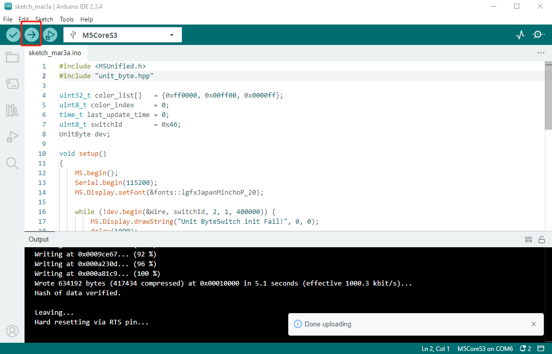
Click the compile and upload button at the top left of the Arduino IDE, and wait for the program to compile and be uploaded to the device.
- Select the Device Port:
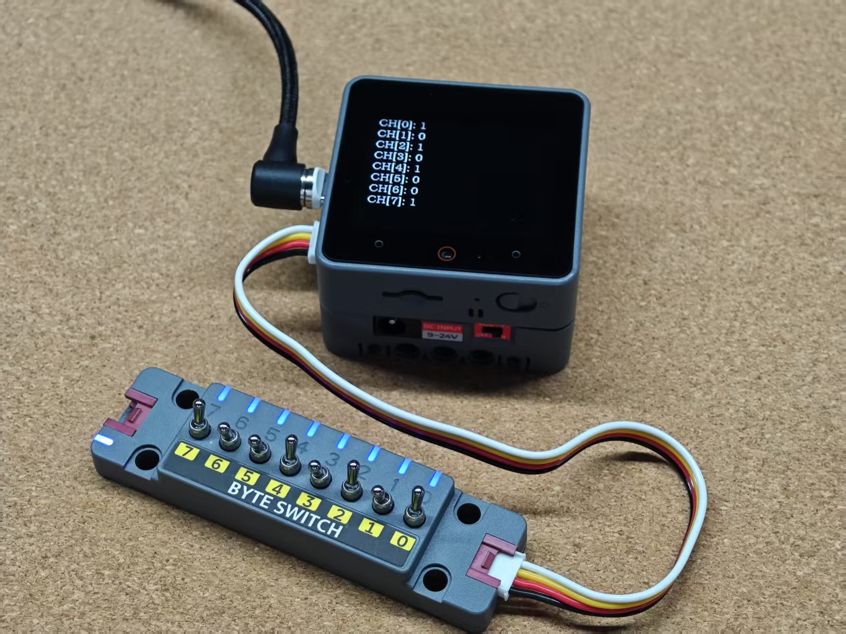
4. Switch Status and LED Control
Real-time display of the switch status and control of RGB LED color switching.
Page Tools