Arduino Quick Start
2. Devices & Examples
3. M5Unified
4. M5GFX
5. Extensions
Unit
Base
IoT
Accessories
Unit ByteButton Arduino Tutorial
1. Preparations
- Environment Setup: Refer to the Arduino IDE Quick Start Guide to install the IDE, and install the corresponding board manager and required driver libraries according to the development board you are using.
- Driver Libraries Used:
- Hardware Products Used:

2. Example
Example Explanation
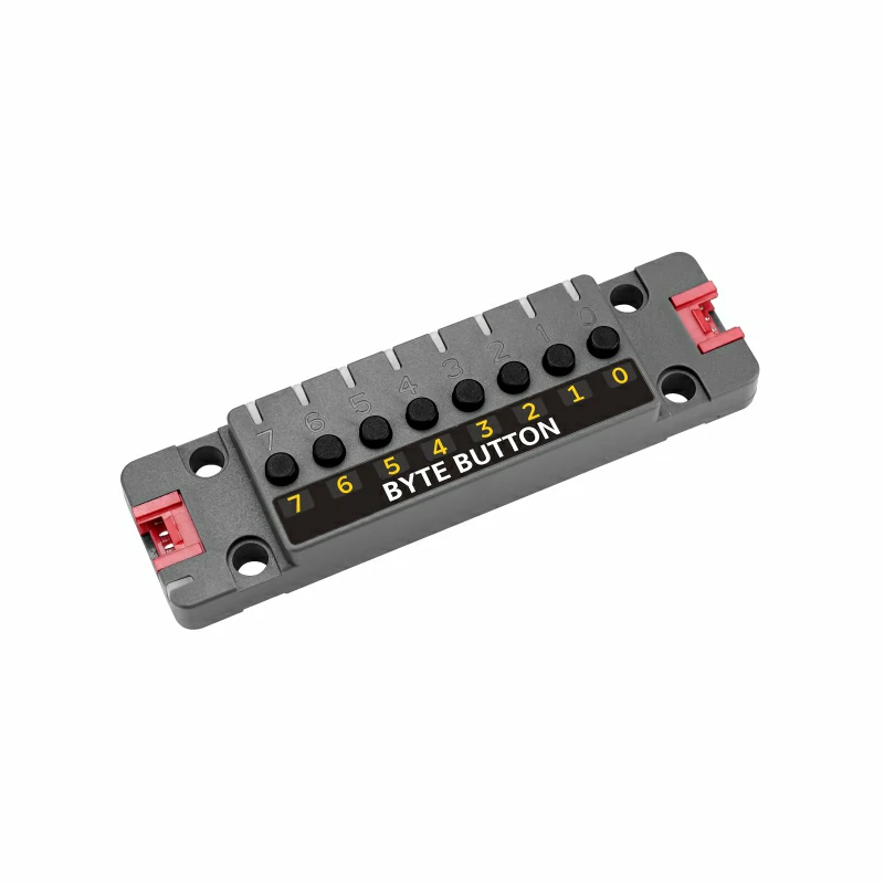
The Unit ByteButton provides 8 physical button inputs and 9 programmable RGB LEDs, making it ideal for multi-button input applications. The RGB LEDs support two operating modes:
- Automatic Mode: Configure the buttons so that in different states they correspond with specific RGB LED colors to achieve synchronized on/off lighting.
- User-Defined Mode: Let the user control the LED color display manually.
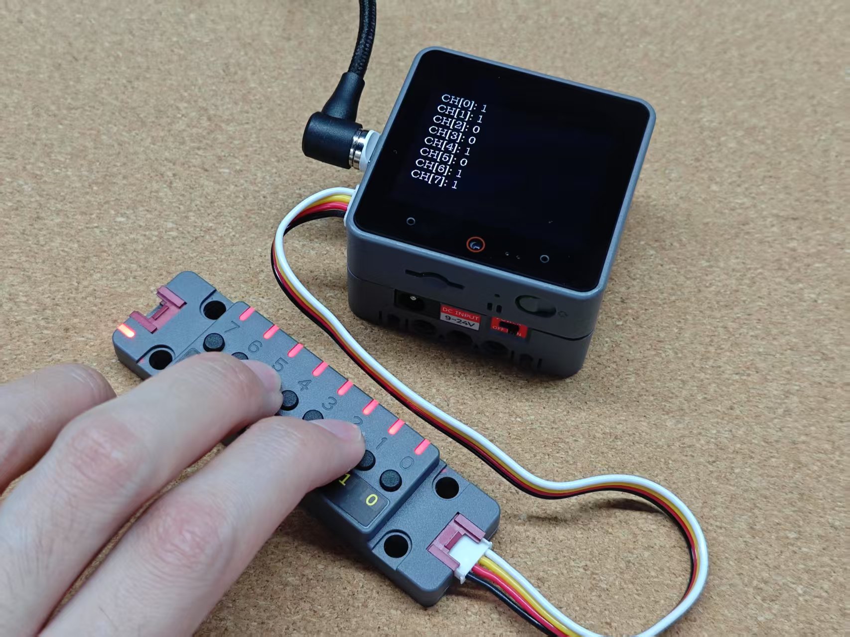
Reading Input
Read the input statuses and configure the RGB LEDs to user-defined mode, updating the LED colors via commands.
cpp
1 2 3 4 5 6 7 8 9 10 11 12 13 14 15 16 17 18 19 20 21 22 23 24 25 26 27 28 29 30 31 32 33 34 35 36 37 38 39 40 41 42
#include <M5Unified.h>
#include "unit_byte.hpp"

uint32_t color_list[]   = {0xff0000, 0x00ff00, 0x0000ff};
uint8_t color_index     = 0;
time_t last_update_time = 0;
uint8_t buttonId        = 0x47;
UnitByte dev;

void setup()
{
    M5.begin();
    Serial.begin(115200);
    M5.Display.setFont(&fonts::lgfxJapanMinchoP_20);

    while (!dev.begin(&Wire, buttonId, 2, 1, 400000)) {
        M5.Display.drawString("Unit ByteButton init Fail!", 0, 0);
        delay(1000);
    }
    dev.setLEDShowMode(BYTE_LED_USER_DEFINED);
    for (uint8_t i = 0; i <= 8; i++) {
        dev.setLEDBrightness(i, 250);
    }
}

void loop()
{
    // M5.Display.clear();
    M5.Display.setCursor(0, 0);
    for (uint8_t i = 0; i < 8; i++) {
        uint8_t buttonStatus8Bytes = dev.getSwitchStatus(i);
        M5.Display.printf("   CH[%d]: %d\r\n", i, buttonStatus8Bytes);
    }

    if (millis() - last_update_time > 1000) {
        color_index = (color_index + 1) % 3;
        for (int i = 0; i <= 8; i++) {
            dev.setRGB888(i, color_list[color_index]);
        }
        last_update_time = millis();
    }
}RGB LED Automatic Mode
Configure the RGB LEDs so that each button has a designated color for its different states, achieving synchronized on/off lighting.
cpp
1 2 3 4 5 6 7 8 9 10 11 12 13 14 15 16 17 18 19 20 21 22 23
const uint32_t colors[] = {
    0xFF0000, 0x0000FF, 0xFFFF00, 0xFF00FF, 0x00FFFF, 0xFFFFFF, 0xFFA500, 0x808080, 0x00FF00,
};
dev.setLEDShowMode(BYTE_LED_MODE_DEFAULT);
Serial.println("Set LED show sys define.");
delay(1000);
dev.setRGB233(8, colors[1]);
delay(1000);
dev.setFlashWriteBack();
delay(1000);
for (int i = 0; i < 8; i++) {
    dev.setSwitchOffRGB888(i, colors[i]);
    // Output the hexadecimal value of the current color
    Serial.printf("Set Switch Off RGB to %06X\n", (unsigned int)colors[i]);
}
delay(1000);
for (int i = 0; i < 8; i++) {
    dev.setSwitchOnRGB888(i, colors[9 - i]);
    // Output the hexadecimal value of the current color
    Serial.printf("Set Switch On RGB to %06X\n", (unsigned int)colors[i]);
}
delay(1000);
dev.setFlashWriteBack();Changing the I2C Address
The Unit ByteButton supports modifying its I2C address, which is convenient when connecting multiple devices simultaneously. Refer to the API below; after initializing the I2C bus, change the device address as needed.
cpp
1 2
dev.begin(&Wire, 2, 1, 400000);
dev.setI2CAddress(new_addr);3. Compile and Upload
- Download Mode:
Different devices require entering download mode before programming, and the procedure may vary depending on the main controller. For details, please refer to the device programming download tutorials listed at the bottom of the Arduino IDE Quick Start Guide.
- For the CoreS3, press and hold the reset button (for about 2 seconds) until the internal green LED lights up, then release it. At this point, the device is in download mode and waiting for programming.
- Download Mode:
.gif)
- Select the Device Port:
Click the compile and upload button at the top-left corner of the Arduino IDE, and wait for the program to compile and be uploaded to the device.
- Select the Device Port:

4. Button Status and LED Control
Real-time display of the button status and control of RGB LED color switching.