Arduino Quick Start
2. Devices & Examples
3. M5Unified
4. M5GFX
5. Extensions & Examples
Unit
Atom DTU
Unit Pbhub v1.1 Arduino Tutorial
1. Preparations
Environment Setup: Refer to Arduino IDE Getting Started Guide to complete IDE installation, and install corresponding board manager and required driver libraries based on the development board used.
Required Driver Libraries:
Required Hardware Products:
- CoreS3
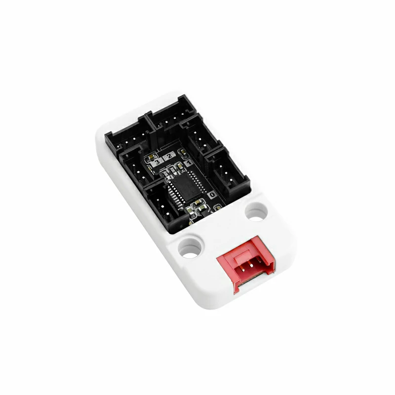
- Unit Pbhub v1.1
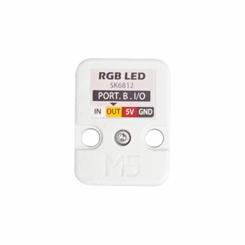
- Unit RGB (Only used when testing RGB functions)
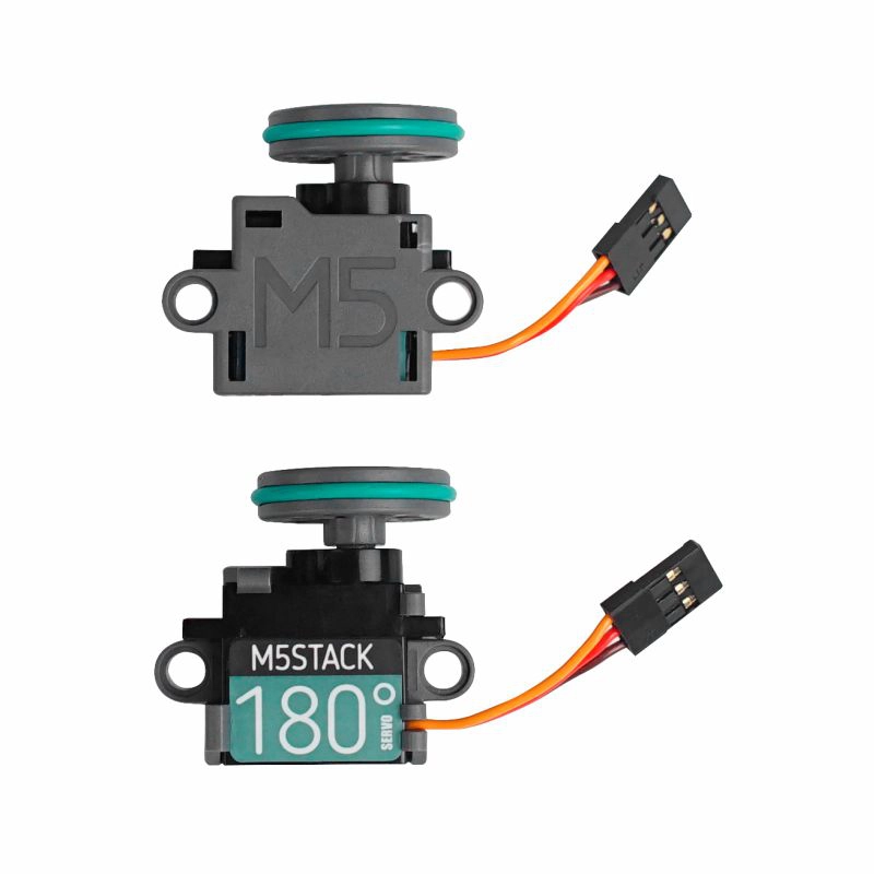
- Servo Kit 180° (Only used when testing servo functions)

2. Notes
Pin Compatibility
Due to different pin configurations across host devices, M5Stack provides an official Pin Compatibility Table for user convenience. Please modify example programs according to actual pin connections.
Pin Definition
This tutorial uses CoreS3 as the main controller paired with Unit Pbhub v1.1. This pin expansion module communicates via I2C. Modify pin definitions in the program according to actual circuit connections. The corresponding IOs after device connection are
G2 (SDA) and G1 (SCL).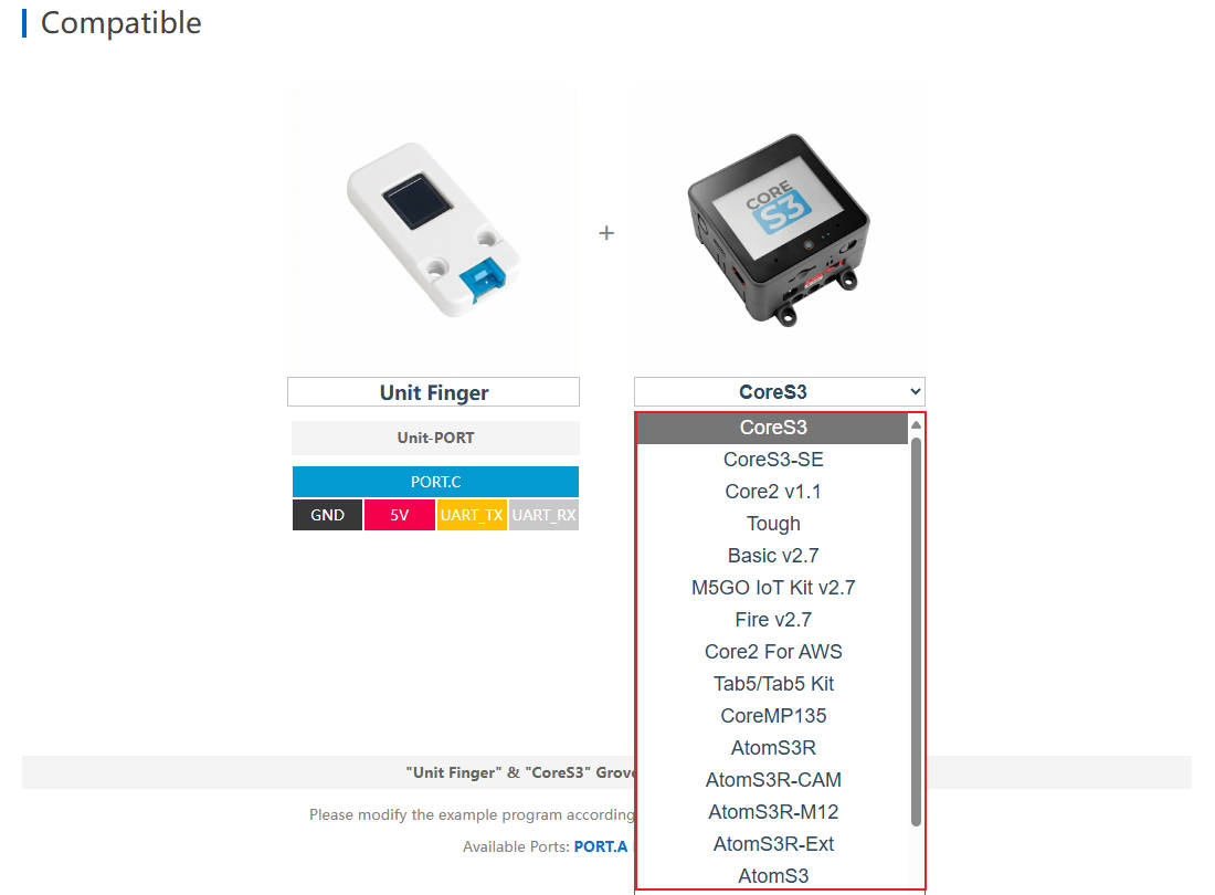
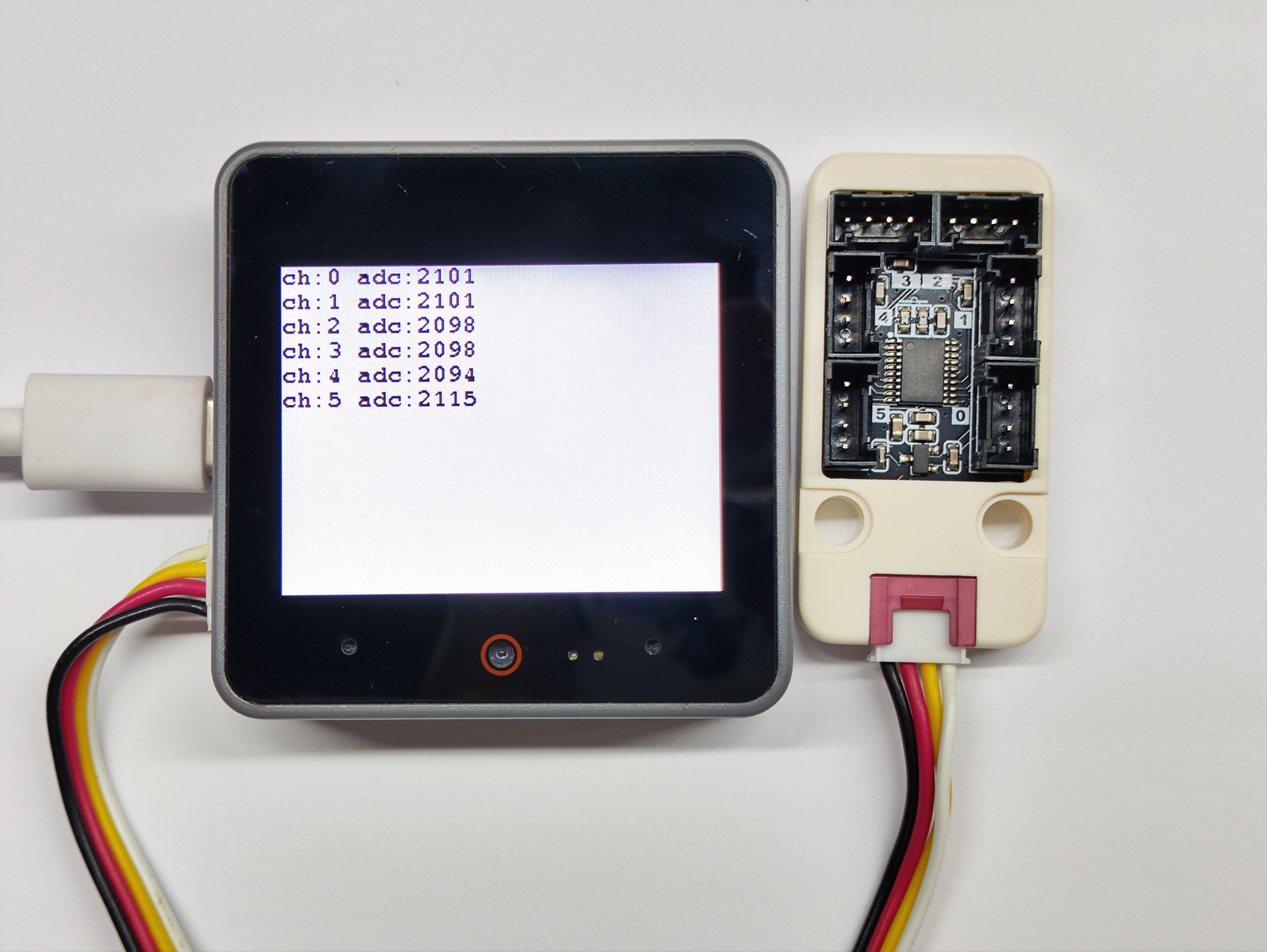
3. Analog Reading Experiment
- Read analog voltage values from all six channels
cpp
1 2 3 4 5 6 7 8 9 10 11 12 13 14 15 16 17 18 19 20 21 22 23 24 25 26 27 28 29 30 31 32
#include "M5Unified.h"
#include "M5UnitPbHub.h"

M5UnitPbHub pbhub;

void setup() {
    M5.begin();
    Serial.begin(115200);
    M5.Display.fillScreen(WHITE);
    M5.Display.setTextColor(BLACK);
    M5.Display.setFont(&fonts::FreeMonoBold9pt7b);
    M5.Display.setCursor(0, 0);
    if (!pbhub.begin(&Wire, UNIT_PBHUB_I2C_ADDR, 2, 1, 400000U)) {
        Serial.println("Couldn't find Pbhub");
        while (1) delay(1);
    }
    Serial.println("Pbhub v1.1 analog_read test");
}

void loop() {
    // ch: 0-5
    // index: 0-1
    // status: 0/1
    for (uint8_t ch = 0; ch < 6; ch++) {
        // only one pin supports analog reading each channel
        Serial.printf("ch:%d adc:%d\r\n", ch, pbhub.analogRead(ch));
        M5.Display.printf("ch:%d adc:%d\r\n", ch, pbhub.analogRead(ch));
        delay(500);
    }
    M5.Display.fillScreen(WHITE);
    M5.Display.setCursor(0, 0);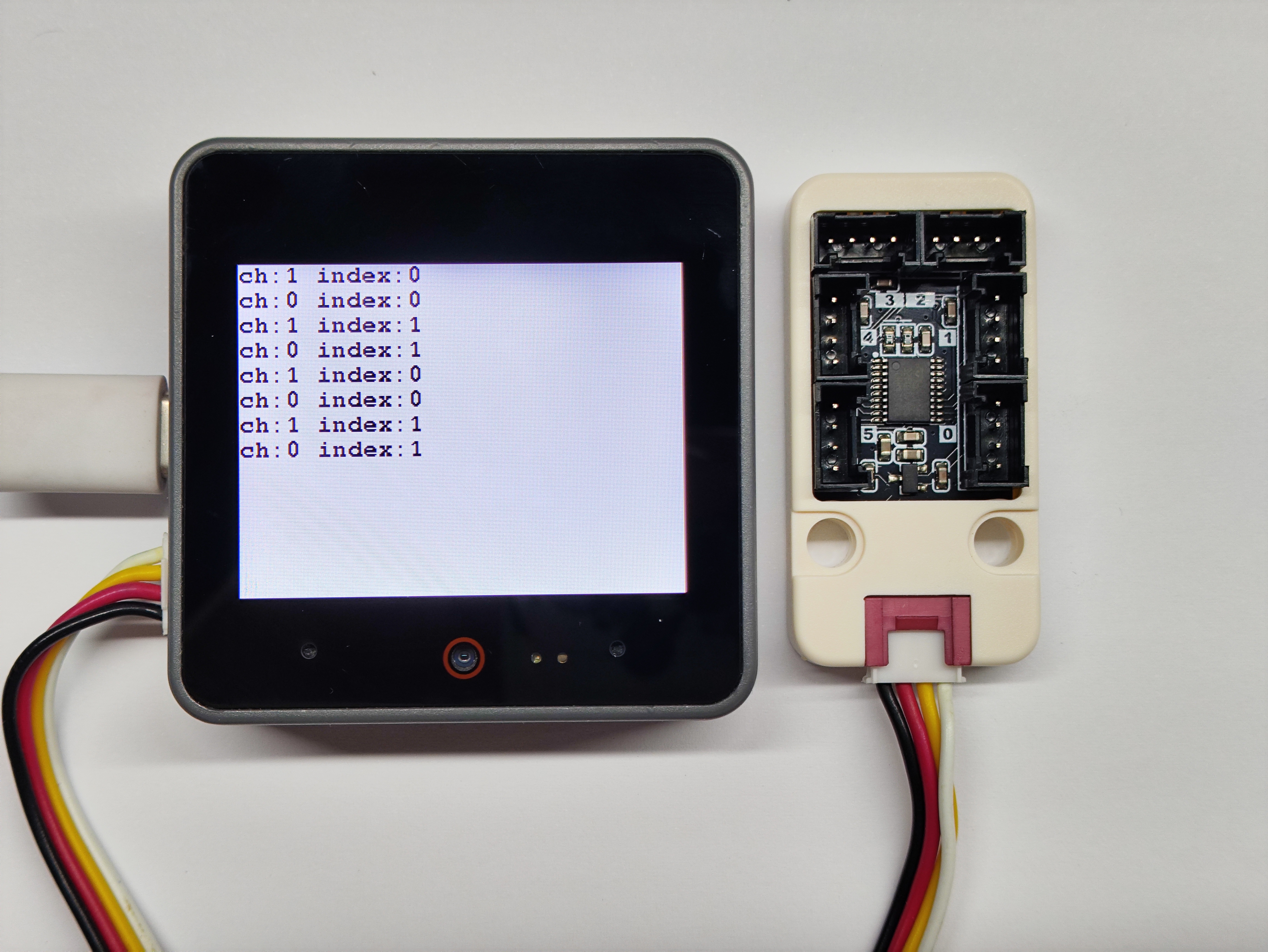
}4. Pin Read/Write Experiment
- Read the pin level status of different channels
cpp
1 2 3 4 5 6 7 8 9 10 11 12 13 14 15 16 17 18 19 20 21 22 23 24 25 26 27 28 29 30 31 32 33 34 35 36 37 38 39 40 41 42 43
#include "M5Unified.h"
#include "M5UnitPbHub.h"

M5UnitPbHub pbhub;

void setup() {
    M5.begin();
    Serial.begin(115200);
    M5.Display.fillScreen(WHITE);
    M5.Display.setTextColor(BLACK);
    M5.Display.setFont(&fonts::FreeMonoBold9pt7b);
    M5.Display.setCursor(0, 0);
    if (!pbhub.begin(&Wire, UNIT_PBHUB_I2C_ADDR, 2, 1, 400000U)) {
        Serial.println("Couldn't find Pbhub");
        while (1) delay(1);
    }
    Serial.println("Pbhub v1.1 digital write read test");
}

void loop() {
    // ch: 0-5
    // index: 0-1
    // status: 0/1
    for (uint8_t ch = 0; ch < 6; ch++) {
        for (uint8_t index = 0; index < 2; index++) {
            pbhub.digitalWrite(ch, index, 1);
            delay(300);
            Serial.printf("ch:%d index:%d\r\n", pbhub.digitalRead(ch, index),
                          index);
            M5.Display.printf("ch:%d index:%d\r\n", pbhub.digitalRead(ch, index),
                          index);
            delay(300);
            pbhub.digitalWrite(ch, index, 0);
            Serial.printf("ch:%d index:%d\r\n", pbhub.digitalRead(ch, index),
                          index);
            M5.Display.printf("ch:%d index:%d\r\n", pbhub.digitalRead(ch, index),
                          index);
            delay(300);
        }
    }
    M5.Display.fillScreen(WHITE);
    M5.Display.setCursor(0, 0);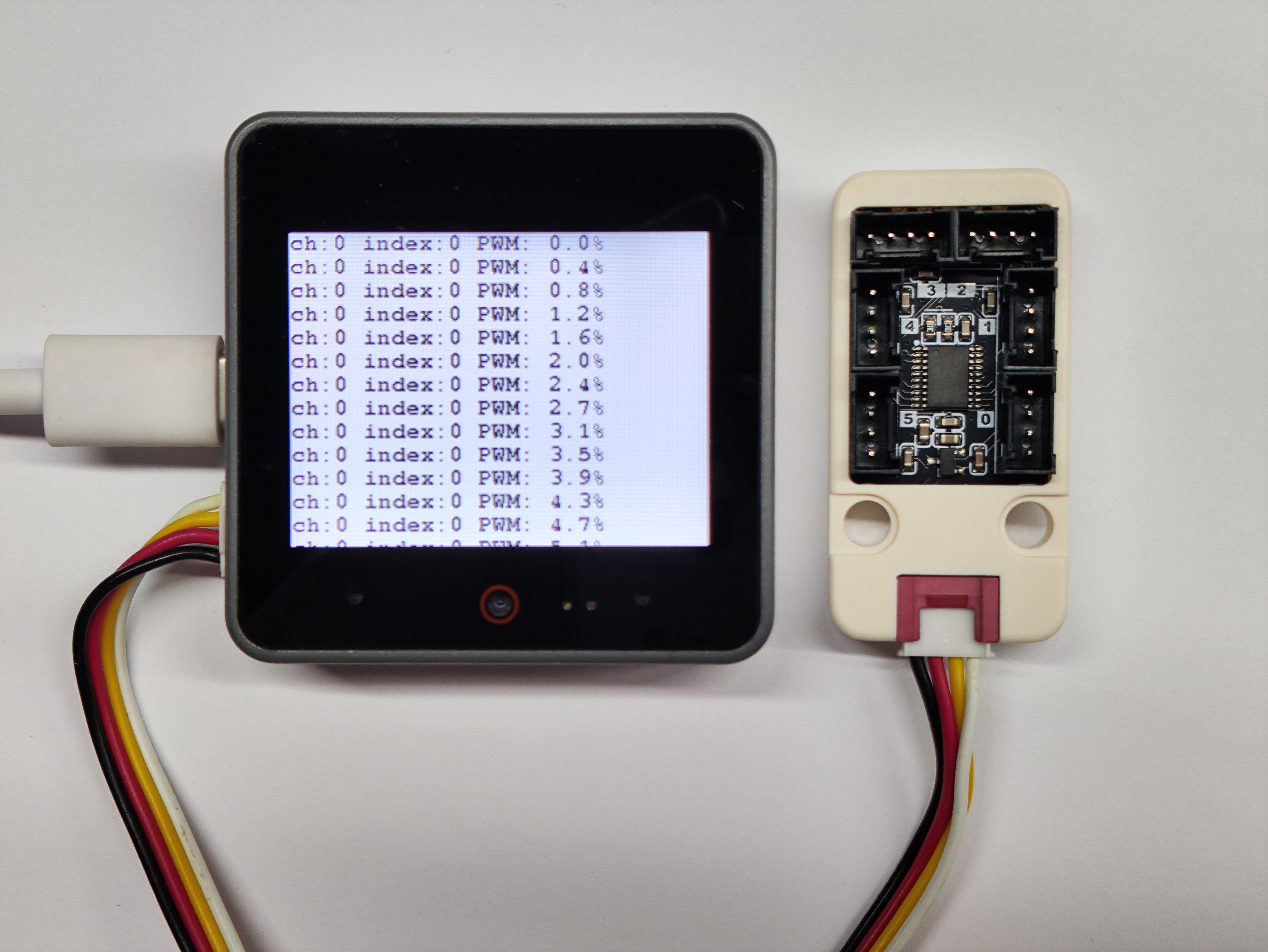
}5. Pin Duty Cycle Setting Experiment
- Set and read duty cycles for different channel pins
cpp
1 2 3 4 5 6 7 8 9 10 11 12 13 14 15 16 17 18 19 20 21 22 23 24 25 26 27 28 29 30 31 32 33 34 35 36 37 38 39
#include "M5Unified.h"
#include "M5UnitPbHub.h"

M5UnitPbHub pbhub;

void setup() {
    M5.begin();
    M5.Display.fillScreen(WHITE);
    M5.Display.setTextColor(BLACK);
    M5.Display.setFont(&fonts::FreeMonoBold9pt7b);
    M5.Display.setCursor(0, 0);
    Serial.begin(115200);
    if (!pbhub.begin(&Wire, UNIT_PBHUB_I2C_ADDR, 2, 1, 400000U)) {
        Serial.println("Couldn't find Pbhub");
        while (1) delay(1);
    }
    Serial.println("Pbhub v1.1 PWM test");
}

void loop() {
    // ch: 0-5
    // index: 0-1
    // status: 0/1
    for (uint8_t ch = 0; ch < 6; ch++) {
        for (uint8_t index = 0; index < 2; index++) {
            for (uint8_t h = 0; h < 255; h++) {
                pbhub.setPWM(ch, index, h);
                Serial.printf("ch:%d index:%d PWM: %.1f%%\r\n", ch, index,
                              h / 255.0 * 100.0);
                M5.Display.printf("ch:%d index:%d PWM: %.1f%%\r\n", ch, index,
                              h / 255.0 * 100.0);
                delay(1000);
            }
        }
        M5.Display.fillScreen(WHITE);
        M5.Display.setCursor(0, 0);
    }
    delay(1000);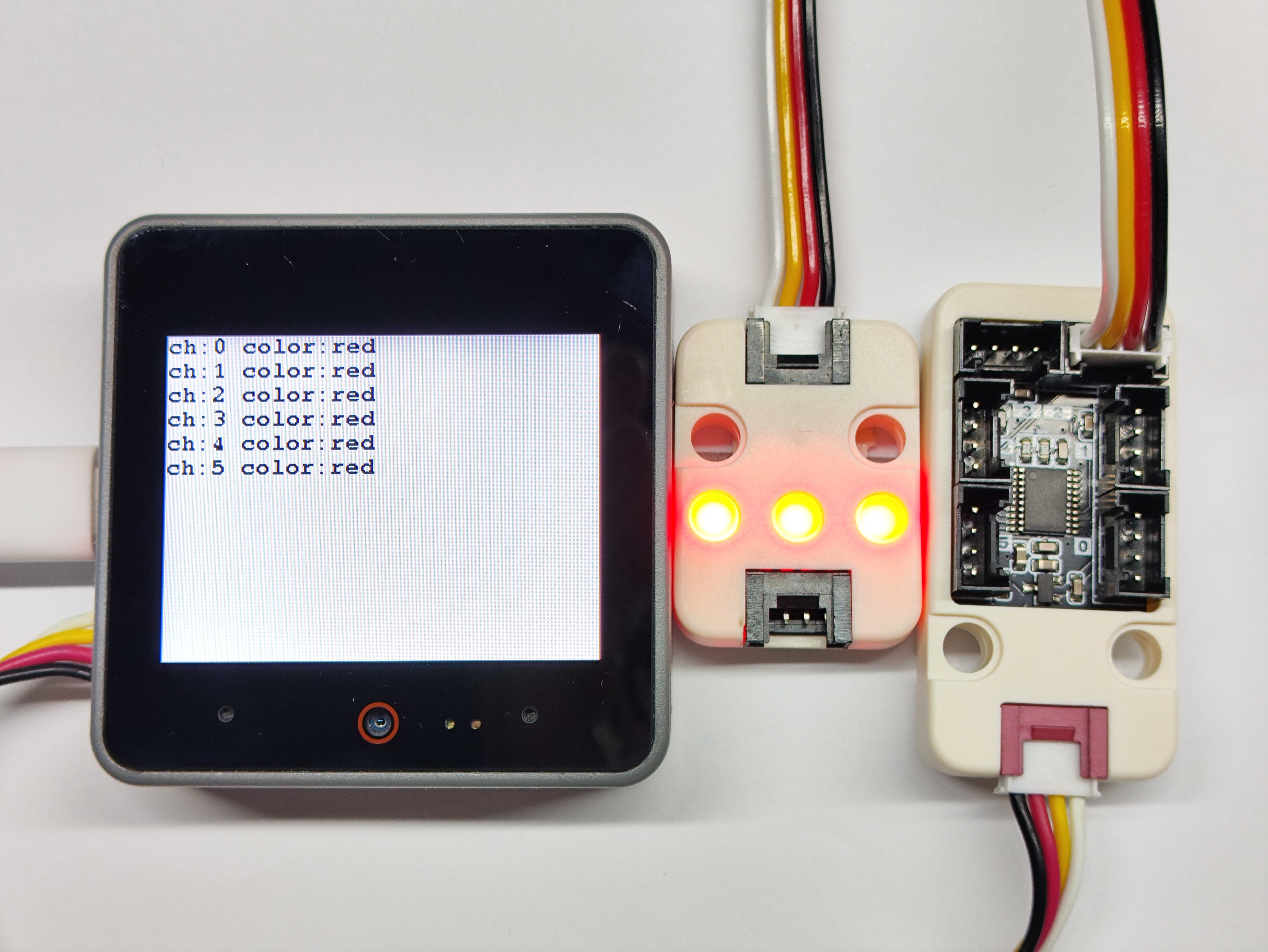
}6. RGB Module Experiment
- Connect external Unit RGB module for color display
cpp
1 2 3 4 5 6 7 8 9 10 11 12 13 14 15 16 17 18 19 20 21 22 23 24 25 26 27 28 29 30 31 32 33 34 35 36 37 38 39 40 41 42 43 44 45 46 47 48 49 50 51 52 53
#include "M5Unified.h"
#include "M5UnitPbHub.h"
M5UnitPbHub pbhub;
void setup()
{
M5.begin();
Serial.begin(115200);
M5.Display.fillScreen(WHITE);
M5.Display.setTextColor(BLACK);
M5.Display.setFont(&fonts::FreeMonoBold9pt7b);
M5.Display.setCursor(0, 0);
if (!pbhub.begin(&Wire, UNIT_PBHUB_I2C_ADDR, 2, 1, 100000U)) {
Serial.println("Couldn't find Pbhub");
while (1) delay(1);
}
for (uint8_t ch = 0; ch < 6; ch++) {
pbhub.setLEDNum(ch, 74);
pbhub.setLEDBrightness(ch, 40);
}
}
void loop()
{
// ch: 0-5
// index: 0-1
// status: 0/1
for (uint8_t ch = 0; ch < 6; ch++) {
pbhub.fillLEDColor(ch, 0, 73, 0xff0000); // Red
Serial.printf("ch:%d color:red\r\n", ch);
M5.Display.printf("ch:%d color:red\r\n", ch);
}
delay(1000);
M5.Display.fillScreen(WHITE);
M5.Display.setCursor(0, 0);
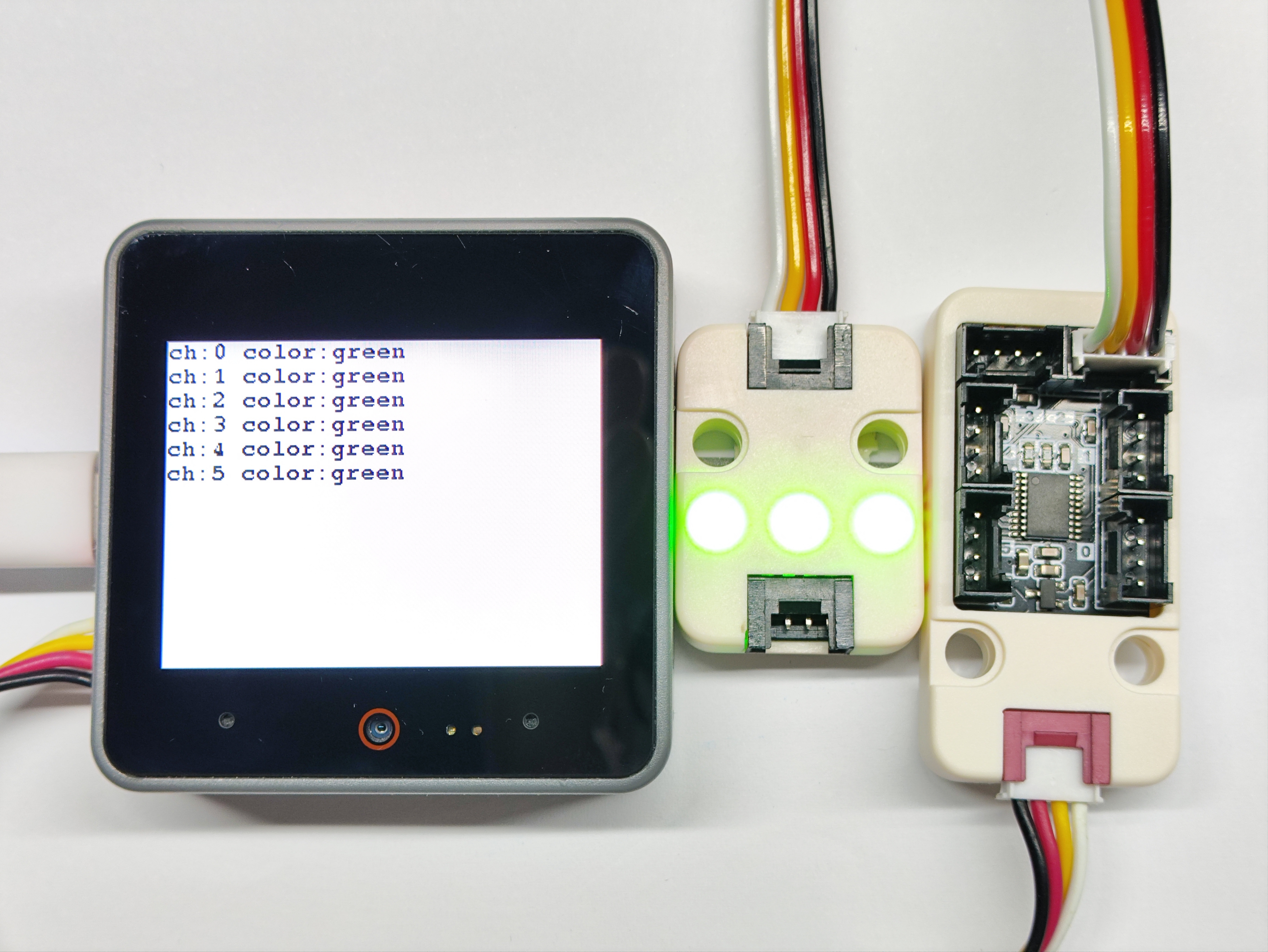
for (uint8_t ch = 0; ch < 6; ch++) {
pbhub.fillLEDColor(ch, 0, 73, 0x00ff00); // Green
Serial.printf("ch:%d color:green\r\n", ch);
M5.Display.printf("ch:%d color:green\r\n", ch);
}
delay(1000);
M5.Display.fillScreen(WHITE);
M5.Display.setCursor(0, 0);
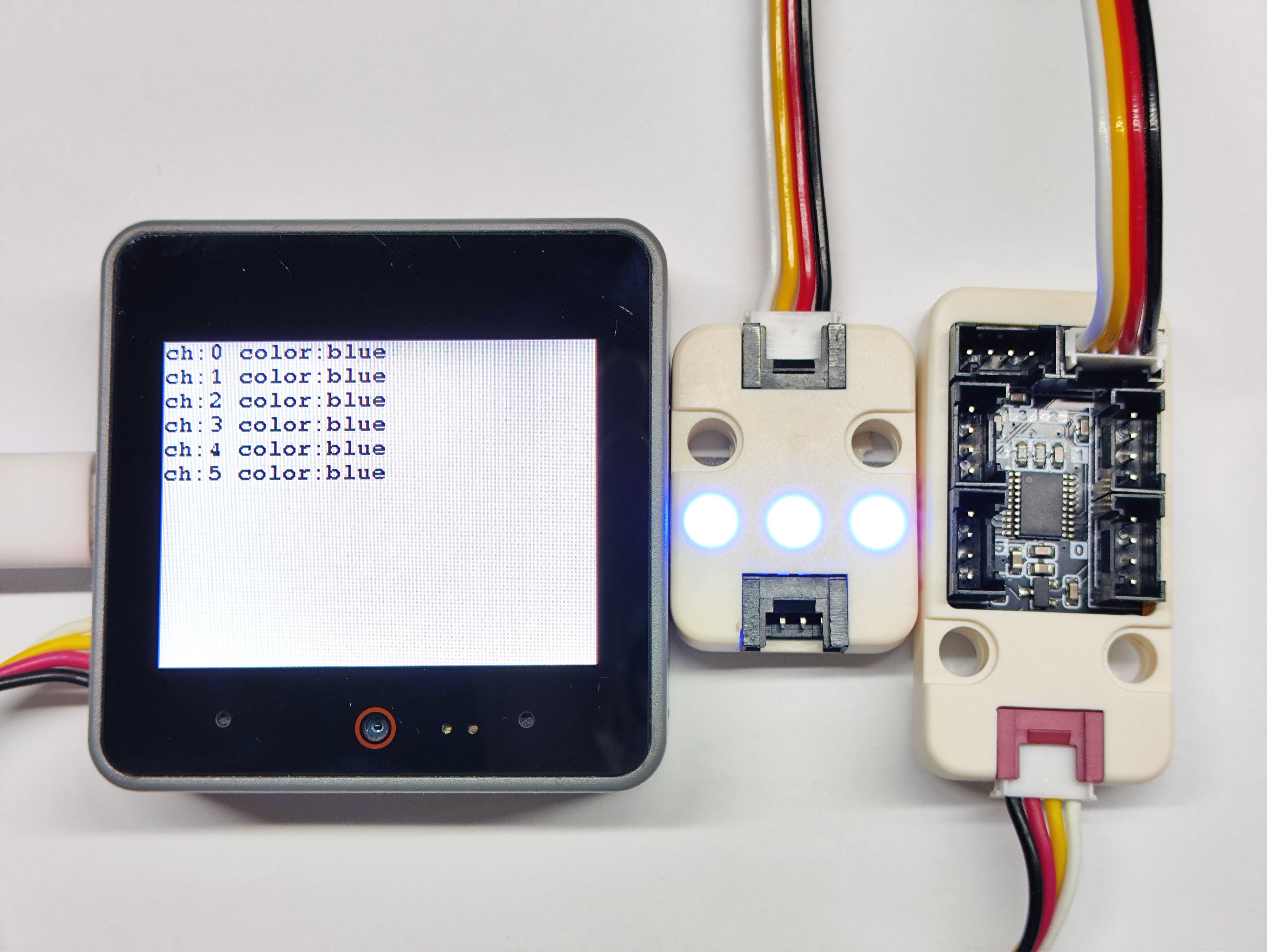
for (uint8_t ch = 0; ch < 6; ch++) {
pbhub.fillLEDColor(ch, 0, 73, 0x0000ff); // Blue
Serial.printf("ch:%d color:blue\r\n", ch);
M5.Display.printf("ch:%d color:blue\r\n", ch);
}
delay(1000);
M5.Display.fillScreen(WHITE);
M5.Display.setCursor(0, 0);
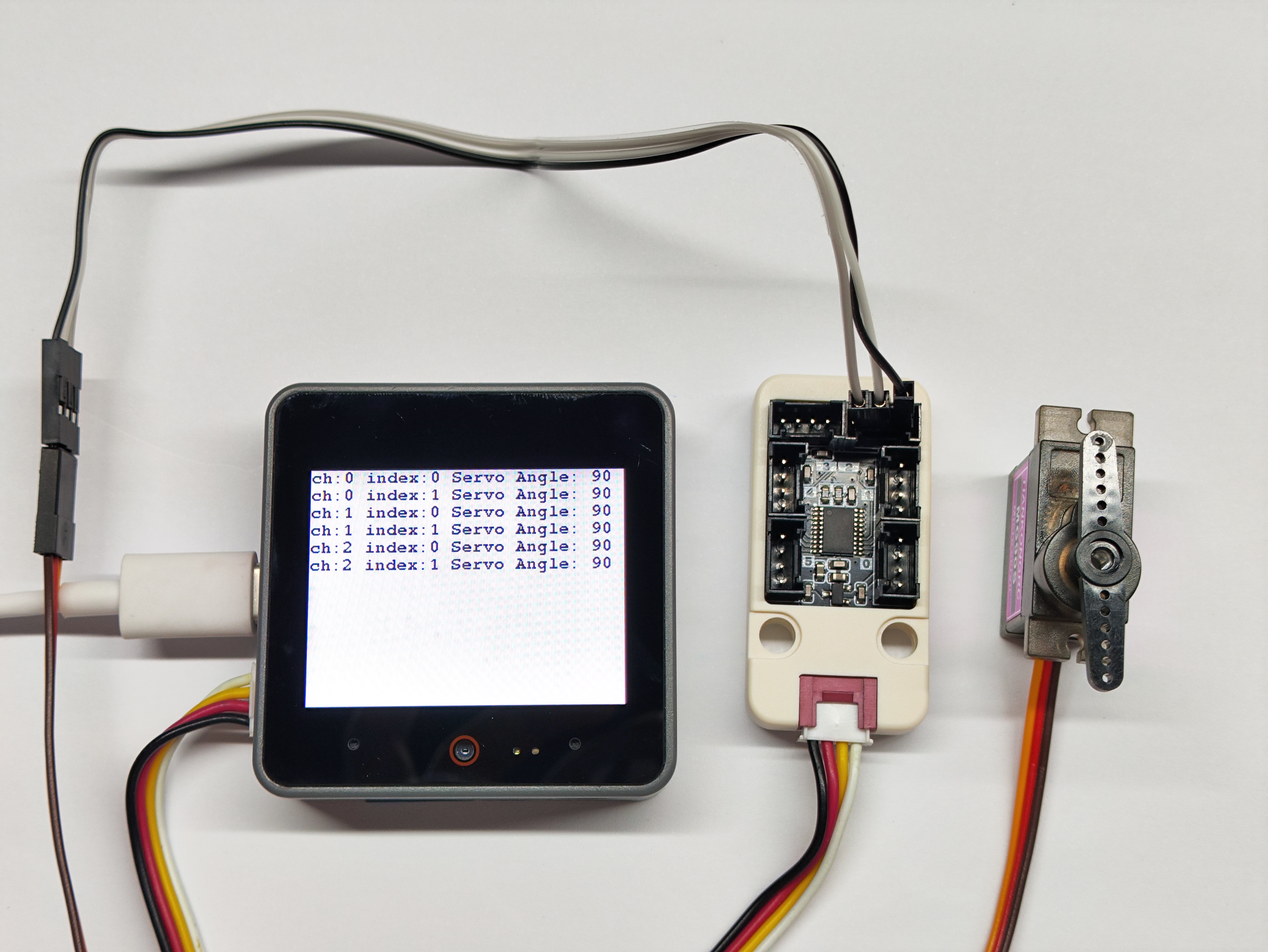
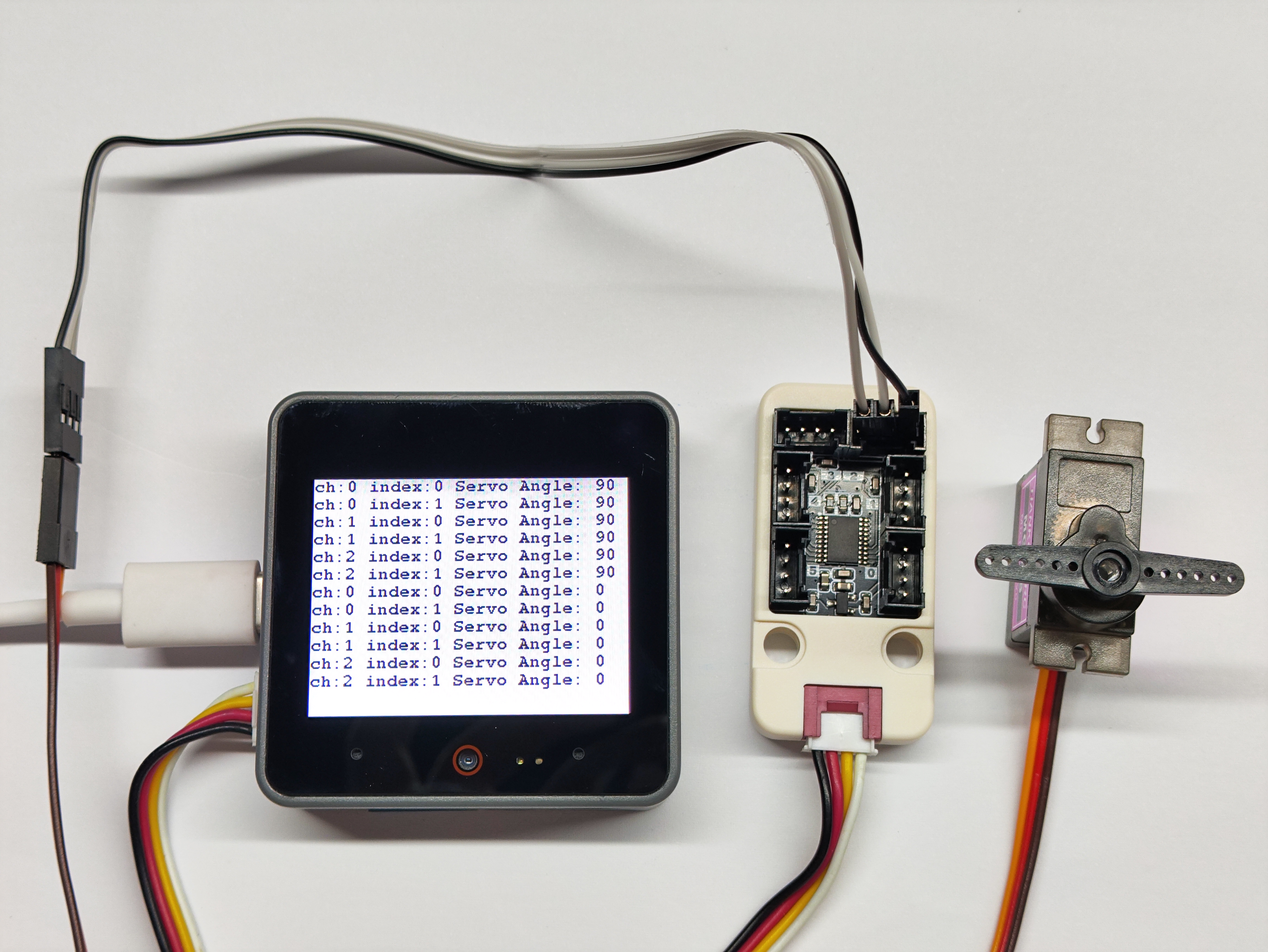
}7. Servo Control Experiment
- Control servo motor to rotate between 0°~90°
Circuit Connection
For servo connection: yellow wire is signal, red wire is 5V, brown wire is GND. Refer to the pinout diagram on the back of Unit Pbhub v1.1 when connecting.
cpp
1 2 3 4 5 6 7 8 9 10 11 12 13 14 15 16 17 18 19 20 21 22 23 24 25 26 27 28 29 30 31 32 33 34 35 36 37 38 39 40 41
#include "M5Unified.h"
#include "M5UnitPbHub.h"
M5UnitPbHub pbhub;

void setup() {
    M5.begin();
    M5.Display.fillScreen(WHITE);
    M5.Display.setTextColor(BLACK);
    M5.Display.setFont(&fonts::FreeMonoBold9pt7b);
    M5.Display.setCursor(0, 0);
    Serial.begin(115200);
    if (!pbhub.begin(&Wire, UNIT_PBHUB_I2C_ADDR, 2, 1, 400000U)) {
        Serial.println("Couldn't find Pbhub");
        while (1) delay(1);
    }
    Serial.println("Pbhub v1.1 Servo test");
}

void loop() {
    // ch: 0-5
    // index: 0-1
    // status: 0/1
    for (uint8_t ch = 0; ch < 3; ch++) {
        for (uint8_t index = 0; index < 2; index++) {
            pbhub.setServoAngle(ch, index, 90);
            Serial.printf("ch:%d index:%d Servo Angle: 90\r\n", ch, index);
            M5.Display.printf("ch:%d index:%d Servo Angle: 90\r\n", ch, index);
        }
    }
    delay(2000);
    for (uint8_t ch = 0; ch < 3; ch++) {
        for (uint8_t index = 0; index < 2; index++) {
            pbhub.setServoAngle(ch, index, 0);
            Serial.printf("ch:%d index:%d Servo Angle: 0\r\n", ch, index);
            M5.Display.printf("ch:%d index:%d Servo Angle: 0\r\n", ch, index);
        }
    }
    delay(2000);
    M5.Display.fillScreen(WHITE);
    M5.Display.setCursor(0, 0);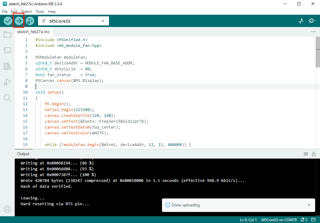
}8. Compile and Upload
Download Mode: Different devices need to enter download mode before programming. This step may vary depending on the main controller. For details, refer to the device-specific programming tutorial list at the bottom of the Arduino IDE Getting Started Guide page.
For CoreS3: Press and hold the reset button (about 2 seconds) until the internal green LED lights up, then release. The device is now in download mode and ready for programming.
.gif)
- Select the device port and click the upload button in the top-left corner of Arduino IDE. Wait for the program to compile and upload to the device.