Arduino Quick Start
2. Devices & Examples
3. M5Unified
4. M5GFX
5. Extensions
Unit
Base
IoT
Accessories
Stamp-C3 Arduino Program Compilation & Upload
1.Preparation
- 1.Arduino IDE Installation: Refer to the Arduino IDE Installation Guide to complete the IDE installation.
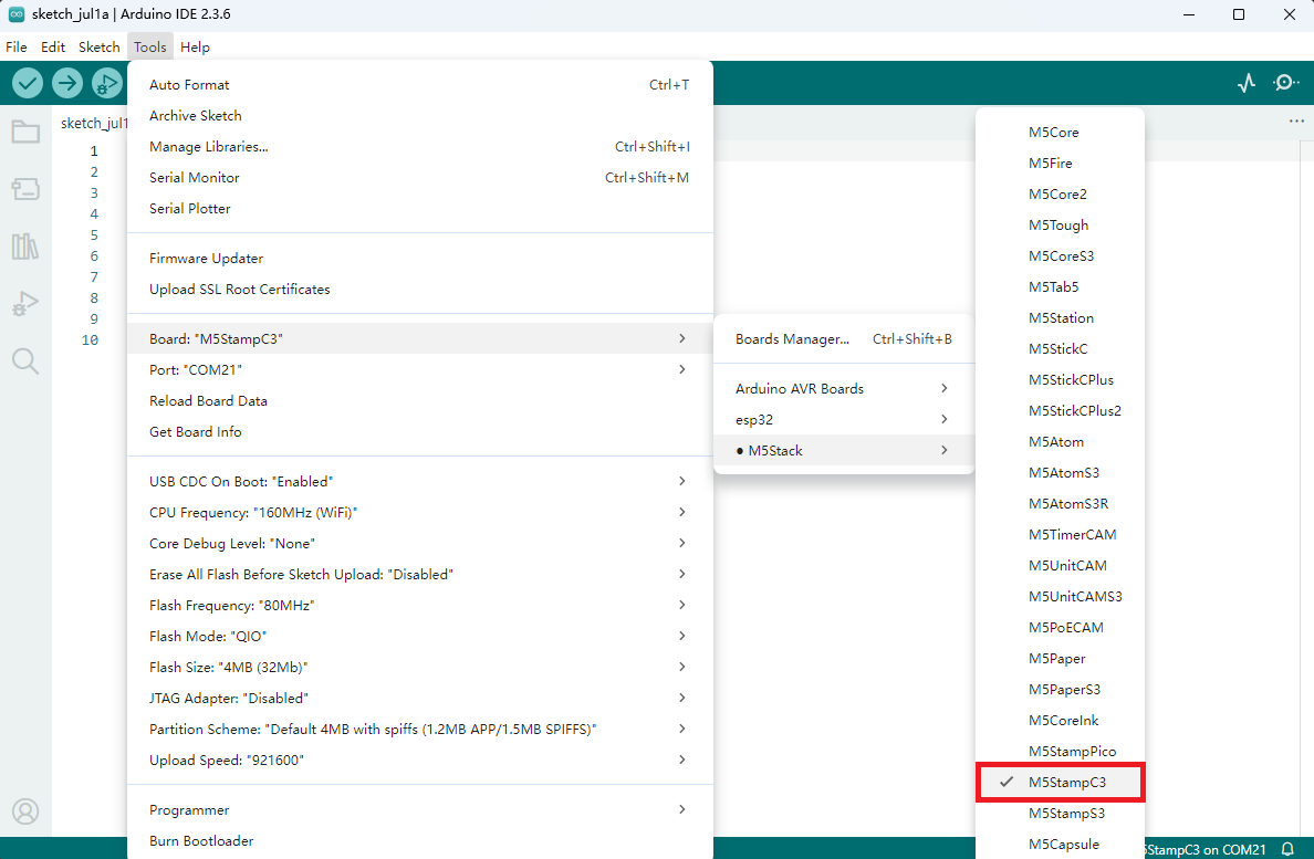
- 2.Board Manager Installation: Refer to the Basic Environment Setup Guide to complete the M5Stack board manager installation and select the development board
M5StampC3.
2.USB Driver Installation
Driver Installation Prompt
Click the link below to download the driver that matches your operating system. After unzipping the compressed package, select the installation package corresponding to the bitness of your operating system. (During the installation of
CH9102_VCP_SER_MacOS v1.7, an error may occur, but the installation is actually completed, so you can ignore it.)| Driver Name | Applicable Driver Chip | Download Link |
|---|---|---|
| CH9102_VCP_SER_Windows | CH9102 | Download |
| CH9102_VCP_SER_MacOS v1.7 | CH9102 | Download |
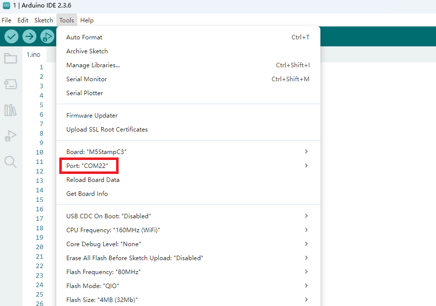
3.Port Selection
Connect the device to the computer via USB, and you can select the corresponding device port in the Arduino IDE.
4.Program Compilation & Upload
Note:
Please set the
Tools -> USB-CDC On Boot option in Arduino IDE to Disabled; otherwise, the serial port cannot be used. The location of this option is as shown in the following picture.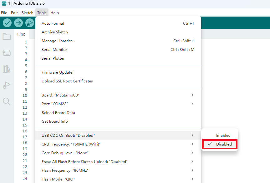
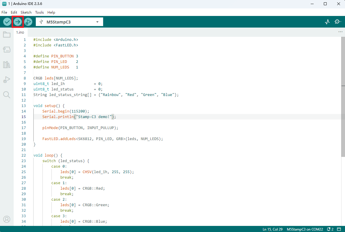
Enter the following code in the Arduino IDE workspace, and click the upload button. The program will be automatically compiled and uploaded.
Note:
cpp
1 2 3 4 5 6 7 8 9 10 11 12 13 14 15 16 17 18 19 20 21 22 23 24 25 26 27 28 29 30 31 32 33 34 35 36 37 38 39 40 41 42 43 44 45 46 47 48 49 50 51 52 53 54
#include <Arduino.h>
#include <FastLED.h>

#define PIN_BUTTON 3
#define PIN_LED    2
#define NUM_LEDS   1

CRGB leds[NUM_LEDS];
uint8_t led_ih             = 0;
uint8_t led_status         = 0;
String led_status_string[] = {"Rainbow", "Red", "Green", "Blue"};

void setup() {
    Serial.begin(115200);
    Serial.println("Stamp-C3 demo!");

    pinMode(PIN_BUTTON, INPUT_PULLUP);

    FastLED.addLeds<SK6812, PIN_LED, GRB>(leds, NUM_LEDS);
}

void loop() {
    switch (led_status) {
        case 0:
            leds[0] = CHSV(led_ih, 255, 255);
            break;
        case 1:
            leds[0] = CRGB::Red;
            break;
        case 2:
            leds[0] = CRGB::Green;
            break;
        case 3:
            leds[0] = CRGB::Blue;
            break;
        default:
            break;
    }
    FastLED.show();
    led_ih++;
    delay(15);

    if (!digitalRead(PIN_BUTTON)) {
        delay(5);
        if (!digitalRead(PIN_BUTTON)) {
            led_status++;
            if (led_status > 3) led_status = 0;
            while (!digitalRead(PIN_BUTTON))
                ;
            Serial.print("LED status updated: ");
            Serial.println(led_status_string[led_status]);
        }
    }
}
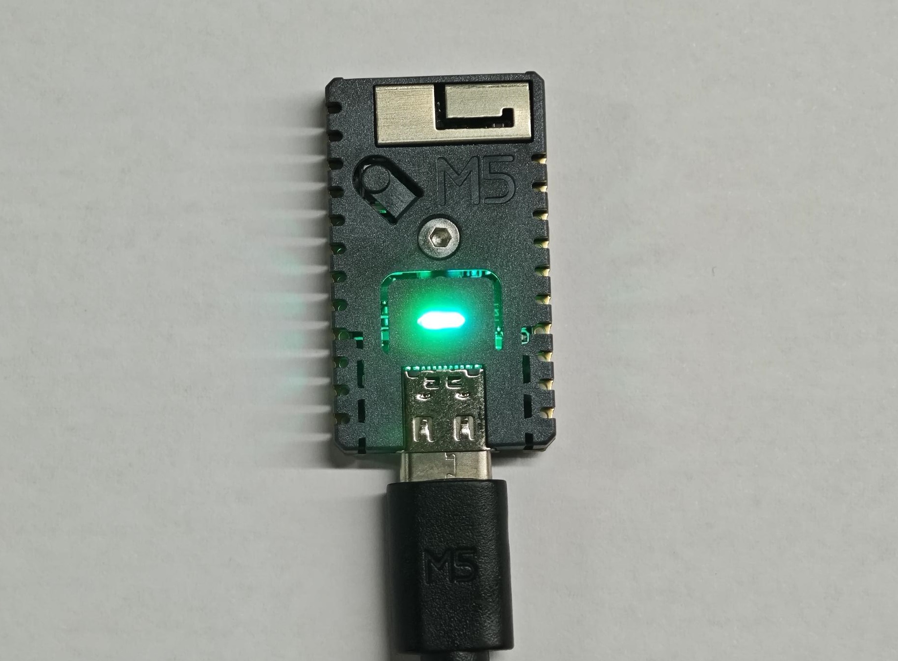
After uploading the code, the RGB LED on the Stamp-C3 device will light up automatically. Pressing the button allows you to cycle through the display colors of the LED. At the same time, the device will output the current light status information (such as color values or modes) through the serial port, facilitating debugging and interactive feedback.