Arduino入門
2. デバイス&サンプル
3. M5Unified
4. M5GFX
5. 拡張モジュール&サンプル
Unit
Atomic
Tab5
IoT
アクセサリー
Sensor Kit
以下はM5GOホストコントローラーがM5GO Kitの6つのUnitセンサーを使用するためのサンプルプログラムです。
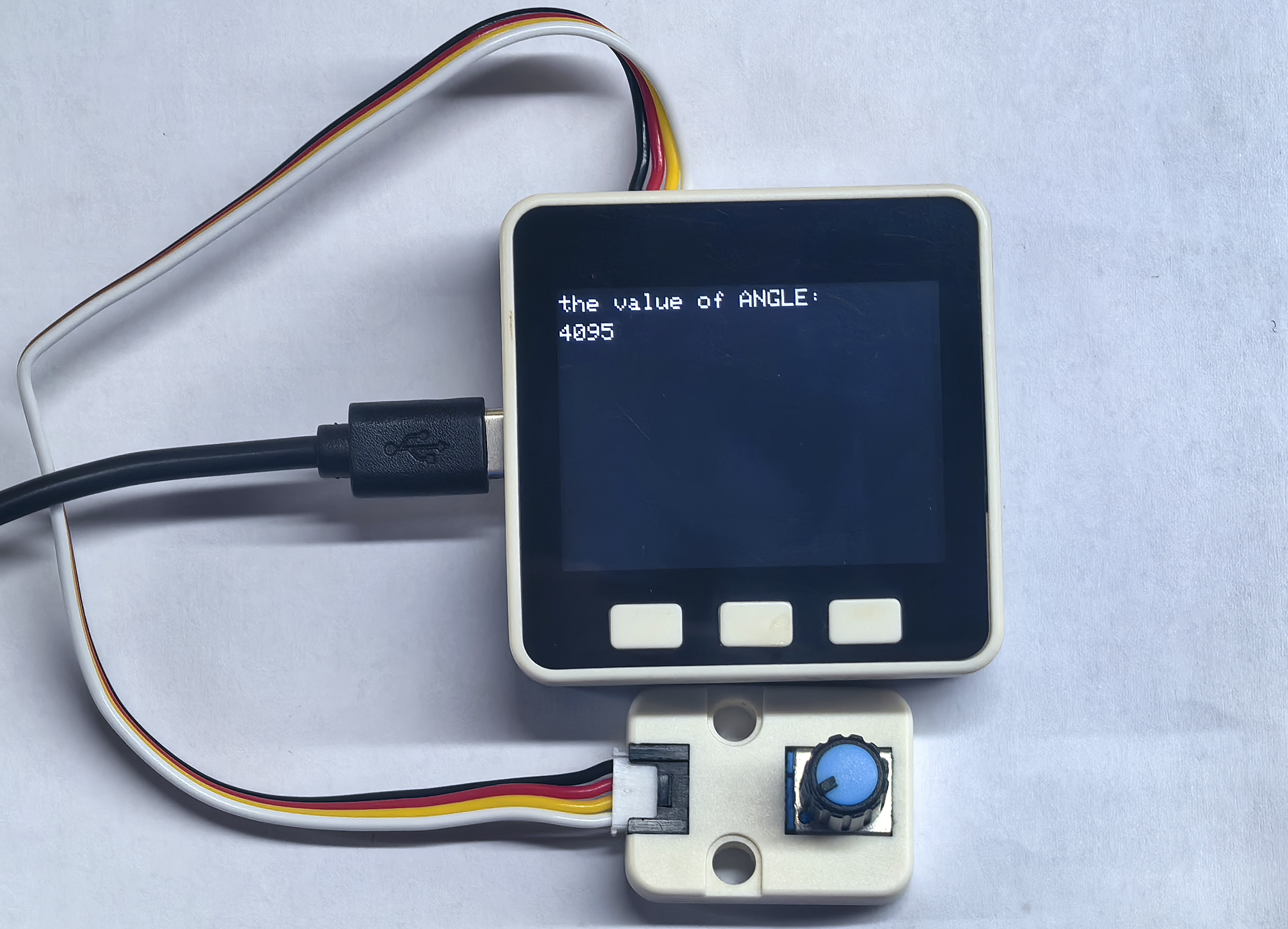
Unit Angle
M5GOでUnit Angleノブの電圧基準値を取得するサンプルプログラム。
サンプルプログラム
#include <M5Unified.h>

int sensorPin        = 36;   // ポテンショメータの入力ピンを設定
int last_sensorValue = 100;  // センサーから最後に読み取った値を保存
int cur_sensorValue  = 0;    // 現在センサーから読み取った値を保存

void setup()
{
    M5.begin();                 // 初期化
    pinMode(sensorPin, INPUT);  // 指定したピンを入力モードに設定
    M5.Lcd.setTextSize(2);      // フォントサイズを2に設定
    M5.Lcd.print("the value of ANGLE: ");
}

void loop()
{
    cur_sensorValue = analogRead(sensorPin);             // センサーから値を取得
    M5.Lcd.setCursor(0, 25);                             // カーソルを(0,25)に移動
    if (abs(cur_sensorValue - last_sensorValue) > 10) {  // チャタリング防止
        M5.Lcd.fillRect(0, 25, 100, 25, BLACK);
        M5.Lcd.print(cur_sensorValue);
        last_sensorValue = cur_sensorValue;
    }
    delay(50);
} このプログラムはUnit Angleノブの電圧基準値をリアルタイムで取得し、画面に表示します。
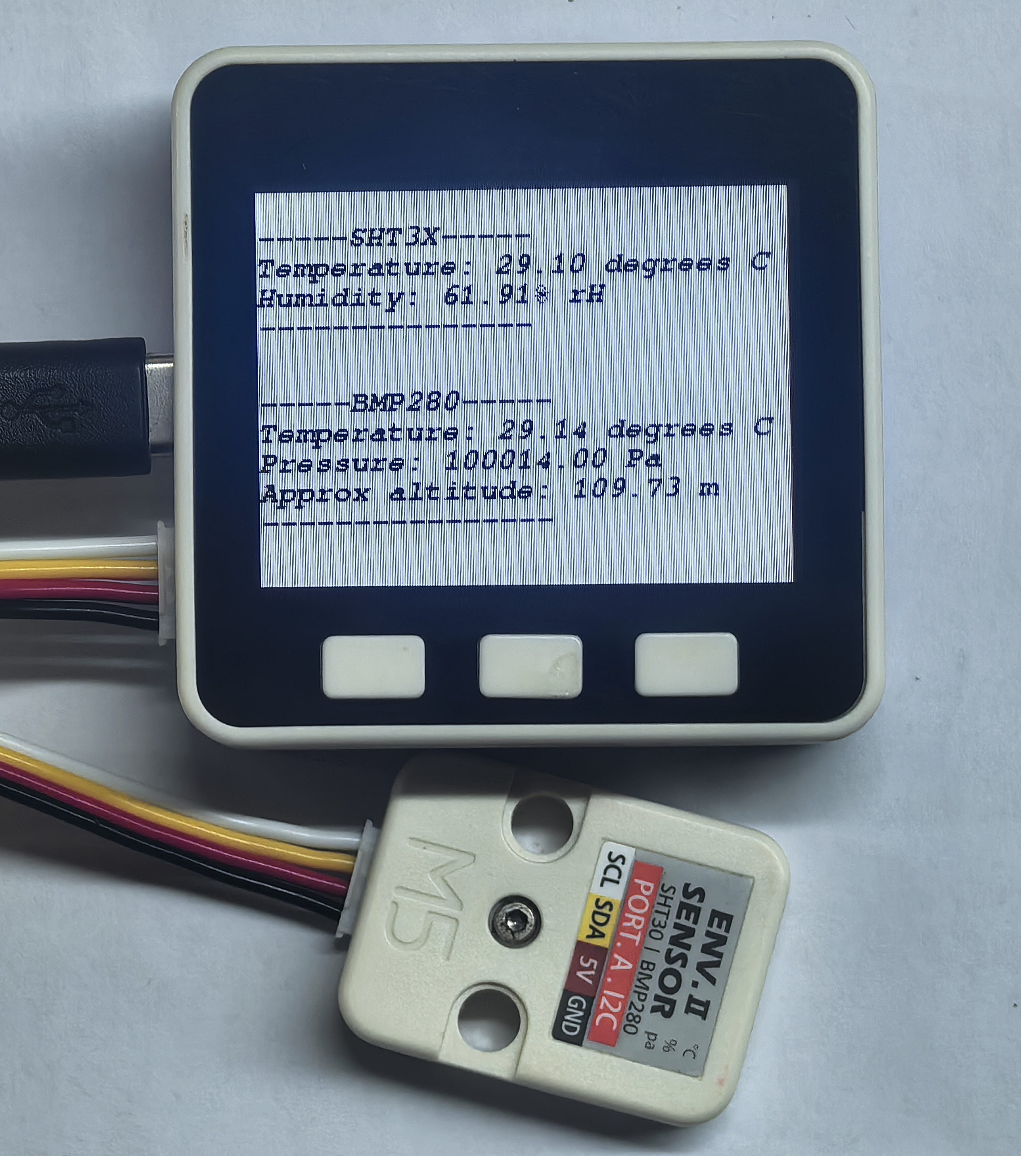
Unit ENV
M5GOでUnit ENVを制御し、温度・湿度、気圧、標高の情報を取得するサンプルプログラム。
サンプルプログラム
1. M5GO Iot Kit -- Unit ENV-II
#include "M5UnitENV.h"
#include "M5Unified.h"

SHT3X sht3x;
BMP280 bmp;
char ENV_SDA = 21;
char ENV_SCL = 22;

void setup() {
    M5.begin();
    M5.Display.setTextColor(TFT_BLACK);
    M5.Display.setTextFont(&fonts::FreeMonoBoldOblique9pt7b);
    M5.Display.clear(TFT_WHITE);

    Serial.begin(115200);

    if (!sht3x.begin(&Wire, SHT3X_I2C_ADDR, ENV_SDA, ENV_SCL, 400000U)) {
        Serial.println("Couldn't find SHT3X\n");
        M5.Display.printf("Couldn't find SHT3X");
        while (1) delay(1);
    }
    else{
        Serial.println("Find SHT3X\n");
        M5.Display.printf("Find SHT3X\n");
    }

    if (!bmp.begin(&Wire, BMP280_I2C_ADDR, ENV_SDA, ENV_SCL, 400000U)) {
        Serial.println("Couldn't find BMP280\n");
        M5.Display.printf("Couldn't find BMP280\n");
        while (1) delay(1);
    }
    else{
        Serial.println("Find BMP280\n");
        M5.Display.printf("Find BMP280\n");
    }
    /* Default settings from datasheet. */
    bmp.setSampling(BMP280::MODE_NORMAL,     /* Operating Mode. */
                    BMP280::SAMPLING_X2,     /* Temp. oversampling */
                    BMP280::SAMPLING_X16,    /* Pressure oversampling */
                    BMP280::FILTER_X16,      /* Filtering. */
                    BMP280::STANDBY_MS_500); /* Standby time. */
    delay(2000);
    M5.Display.clear(TFT_WHITE);
}

void loop() {
    if (sht3x.update()) {
        Serial.println("-----SHT3X-----");
        Serial.print("Temperature: ");
        Serial.print(sht3x.cTemp);
        Serial.println(" degrees C");
        Serial.print("Humidity: ");
        Serial.print(sht3x.humidity);
        Serial.println("% rH");
        Serial.println("---------------\r\n");

        M5.Display.fillRect(0, 0, 320, 120, TFT_WHITE);
        M5.Display.setCursor(0, 20);
        M5.Display.println("-----SHT3X-----");
        M5.Display.print("Temperature: ");
        M5.Display.print(sht3x.cTemp);
        M5.Display.println(" degrees C");
        M5.Display.print("Humidity: ");
        M5.Display.print(sht3x.humidity);
        M5.Display.println("% rH");
        M5.Display.println("---------------\r\n");
    }

    if (bmp.update()) {
        Serial.println("-----BMP280-----");
        Serial.print(F("Temperature: "));
        Serial.print(bmp.cTemp);
        Serial.println(" degrees C");
        Serial.print(F("Pressure: "));
        Serial.print(bmp.pressure);
        Serial.println(" Pa");
        Serial.print(F("Approx altitude: "));
        Serial.print(bmp.altitude);
        Serial.println(" m");
        Serial.println("----------------\r\n");

        M5.Display.fillRect(0, 120, 320, 120, TFT_WHITE);
        M5.Display.setCursor(0, 120);
        M5.Display.println("-----BMP280-----");
        M5.Display.print(F("Temperature: "));
        M5.Display.print(bmp.cTemp);
        M5.Display.println(" degrees C");
        M5.Display.print(F("Pressure: "));
        M5.Display.print(bmp.pressure);
        M5.Display.println(" Pa");
        M5.Display.print(F("Approx altitude: "));
        M5.Display.print(bmp.altitude);
        M5.Display.println(" m");
        M5.Display.println("----------------\r\n");
    }
    delay(1000);
} このプログラムは、画面上に SHT3X と BMP280 で取得した温度・湿度、気圧、標高の情報を1秒ごとに表示します。
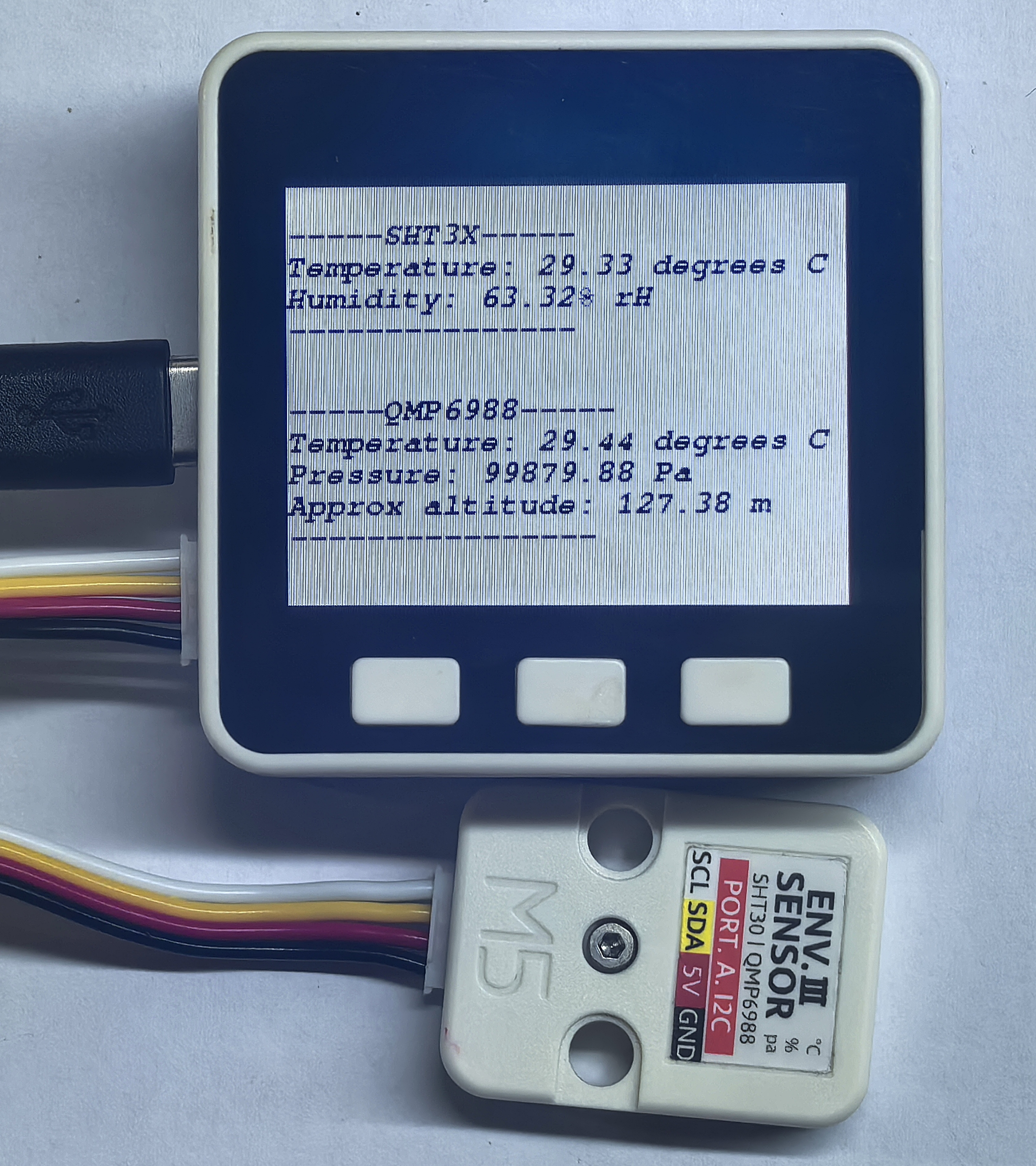
2. M5GO Iot Kit 2.6 / M5GO Iot Kit 2.7 -- Unit ENV-II
#include "M5UnitENV.h"
#include "M5Unified.h"

SHT3X sht3x;
QMP6988 qmp;
char ENV_SDA = 21;
char ENV_SCL = 22;

void setup() {
    M5.begin();
    M5.Display.setTextColor(TFT_BLACK);
    M5.Display.setTextFont(&fonts::FreeMonoBoldOblique9pt7b);
    M5.Display.clear(TFT_WHITE);

    Serial.begin(115200);

    if (!sht3x.begin(&Wire, SHT3X_I2C_ADDR, ENV_SDA, ENV_SCL, 400000U)) {
        Serial.println("Couldn't find SHT3X\n");
        M5.Display.printf("Couldn't find SHT3X");
        while (1) delay(1);
    }
    else{
        Serial.println("Find SHT3X\n");
        M5.Display.printf("Find SHT3X\n");
    }

    if (!qmp.begin(&Wire, QMP6988_SLAVE_ADDRESS_L, 21, 22, 400000U)) {
        Serial.println("Couldn't find QMP6988\n");
        M5.Display.printf("Couldn't find QMP6988\n");
        while (1) delay(1);
    }
    else{
        Serial.println("Find QMP6988\n");
        M5.Display.printf("Find QMP6988\n");
    }

    delay(2000);
    M5.Display.clear(TFT_WHITE);
}

void loop() {
    if (sht3x.update()) {
        Serial.println("-----SHT3X-----");
        Serial.print("Temperature: ");
        Serial.print(sht3x.cTemp);
        Serial.println(" degrees C");
        Serial.print("Humidity: ");
        Serial.print(sht3x.humidity);
        Serial.println("% rH");
        Serial.println("---------------\r\n");

        M5.Display.fillRect(0, 0, 320, 120, TFT_WHITE);
        M5.Display.setCursor(0, 20);
        M5.Display.println("-----SHT3X-----");
        M5.Display.print("Temperature: ");
        M5.Display.print(sht3x.cTemp);
        M5.Display.println(" degrees C");
        M5.Display.print("Humidity: ");
        M5.Display.print(sht3x.humidity);
        M5.Display.println("% rH");
        M5.Display.println("---------------\r\n");
    }

    if (qmp.update()) {
        Serial.println("-----QMP6988-----");
        Serial.print(F("Temperature: "));
        Serial.print(qmp.cTemp);
        Serial.println(" degrees C");
        Serial.print(F("Pressure: "));
        Serial.print(qmp.pressure);
        Serial.println(" Pa");
        Serial.print(F("Approx altitude: "));
        Serial.print(qmp.altitude);
        Serial.println(" m");
        Serial.println("----------------\r\n");

        M5.Display.fillRect(0, 120, 320, 120, TFT_WHITE);
        M5.Display.setCursor(0, 120);
        M5.Display.println("-----QMP6988-----");
        M5.Display.print(F("Temperature: "));
        M5.Display.print(qmp.cTemp);
        M5.Display.println(" degrees C");
        M5.Display.print(F("Pressure: "));
        M5.Display.print(qmp.pressure);
        M5.Display.println(" Pa");
        M5.Display.print(F("Approx altitude: "));
        M5.Display.print(qmp.altitude);
        M5.Display.println(" m");
        M5.Display.println("----------------\r\n");
    }
    delay(1000);
} このプログラムは、画面上に SHT3X と QMP6988 で取得した温度・湿度、気圧、標高の情報を1秒ごとに表示します。
Unit HUB
Unit HUBの主な役割は、一つのGroveポートを三つに拡張し、ユーザーが複数のI2Cデバイスを同時に接続できるようにすることです。内部のすべてのポートの信号は並列接続されており、異なるI2Cアドレスを通じて複数のI2Cデバイスを制御できます。
Unit IR
M5GOでUnit IRを制御し、赤外線NECコーディングの送受信を実現するサンプルプログラム。
サンプルプログラム
#include <IRremote.hpp>
#include <M5Unified.h>

#define IR_SEND_PIN    21      // IR送信機のGPIOピン
#define IR_RECEIVE_PIN 22      // IR受信機のGPIOピン

// デモパラメータ(NECプロトコル用)
uint16_t address = 0x0000;     // デバイスの初期アドレス
uint8_t  command = 0x55;       // コマンドの初期値
uint8_t  repeats = 0;          // リピート送信回数

void setup() {
    M5.begin();                // M5Stackデバイスを初期化
    Serial.begin(115200);      // シリアル通信(115200ボー)
    delay(200);                // シリアルポートの安定を待つ

    // 表示設定
    M5.Display.setTextColor(TFT_BLACK);
    M5.Display.setTextFont(&fonts::FreeMonoBoldOblique9pt7b);
    M5.Display.clear(TFT_WHITE);
    M5.Display.setCursor(0,0);
    M5.Display.printf("M5GO IRremote example");
    Serial.println("M5GO IRremote example");
    // IR通信初期化
    IrReceiver.begin(IR_RECEIVE_PIN);     // IR受信開始
    IrSender.begin(DISABLE_LED_FEEDBACK);  // LEDフィードバックなしで送信機初期化
    IrSender.setSendPin(IR_SEND_PIN);      // 送信ピンを指定
    Serial.printf("IR Send Pin: %d, IR Recv Pin: %d\n", IR_SEND_PIN, IR_RECEIVE_PIN);
    delay(500); // ハード安定待ち
}

void loop() {
    // 1. NECプロトコルによる赤外線送信
    Serial.printf("Send NEC: addr=0x%04x, cmd=0x%02x\n", address, command);
    IrSender.sendNEC(address, command, repeats);

    // 送信情報を画面に表示
    M5.Display.fillRect(0, 20, 320, 90, TFT_WHITE);  // 前の内容をクリア
    M5.Display.setCursor(0, 40);
    M5.Display.printf("Send NEC:\n addr=0x%04x\n cmd=0x%02x\n", address, command);
    IrReceiver.restartAfterSend();  // 送信後に受信再開
    // 2. 反射受信(至近距離テスト)を待機
    delay(20);  // 受信待ち
    // 受信データのデコードを試みる
    if (IrReceiver.decode()) {
        // シリアルモニターに受信データを出力
        Serial.printf("Received: protocol=%s, addr=0x%04x, cmd=0x%02x, raw=0x%08lx\n",
                      getProtocolString(IrReceiver.decodedIRData.protocol),
                      IrReceiver.decodedIRData.address,
                      IrReceiver.decodedIRData.command,
                      (unsigned long)IrReceiver.decodedIRData.decodedRawData);

        // 受信データを画面表示
        M5.Display.fillRect(0, 110, 320, 130, TFT_WHITE);  // 前の内容をクリア
        M5.Display.setCursor(0, 110);
        M5.Display.printf("Received:\n protocol=%s\n addr=0x%04x\n cmd=0x%02x\n raw=0x%08lx\n",
                        getProtocolString(IrReceiver.decodedIRData.protocol),
                        IrReceiver.decodedIRData.address,
                        IrReceiver.decodedIRData.command,
                        (unsigned long)IrReceiver.decodedIRData.decodedRawData);

        IrReceiver.resume();  // 次信号の受信を有効化
    } else {
        // 受信なしの場合
        Serial.println("No IR received.");
        M5.Display.fillRect(0, 110, 320, 130, TFT_WHITE);  // 前内容クリア
        M5.Display.setCursor(0, 110);
        M5.Display.println("No IR received.");
    }
    // 次のサイクル用に送信パラメータを更新
    address += 0x0001;  // デバイスアドレスをインクリメント
    command += 0x01;     // コマンドコードをインクリメント
    repeats  = 0;        // リピートフレームは無効(テストする場合は>0に)
    delay(2000);  // メインループディレイ(2秒)
} このプログラムはUnit IRで赤外線NEC信号を送受信し、NECコード関連の情報を画面に表示します。
Unit PIR
M5GOでUnit PIRを制御し、赤外線放射検出サンプルプログラム。
サンプルプログラム
#include <M5Unified.h>

char sensorPin = 36;

void setup()
{
    M5.begin();             // M5GO初期化
    M5.Display.setTextColor(TFT_BLACK);
    M5.Display.setTextFont(&fonts::FreeMonoBoldOblique9pt7b);
    M5.Display.clear(TFT_WHITE);
    M5.Lcd.println("PIR example");
    M5.Lcd.setCursor(0, 25);  // カーソルを(0,25)に配置
    M5.Lcd.println("Status: \nValue: ");
    pinMode(sensorPin, INPUT);  // sensorPinピンを入力モードに設定
}

void loop()
{
    M5.Lcd.fillRect(90, 25, 180, 50, TFT_WHITE);  // (90,25)に180×50の白い矩形を描く
    if (digitalRead(sensorPin) == 1) {            // pin sensorPinの値が1なら
        M5.Lcd.setCursor(95, 25);
        M5.Lcd.print("Sensing");
        M5.Lcd.setCursor(95, 45);
        M5.Lcd.print("1");
    } else {
        M5.Lcd.setCursor(95, 25);
        M5.Lcd.print("Not Sensed");
        M5.Lcd.setCursor(95, 45);
        M5.Lcd.print("0");
    }
    delay(500);
} このプログラムはUnit PIRで赤外線放射を検知し、画面に検出状態を表示します。注意:この検出には一定の遅延があります。
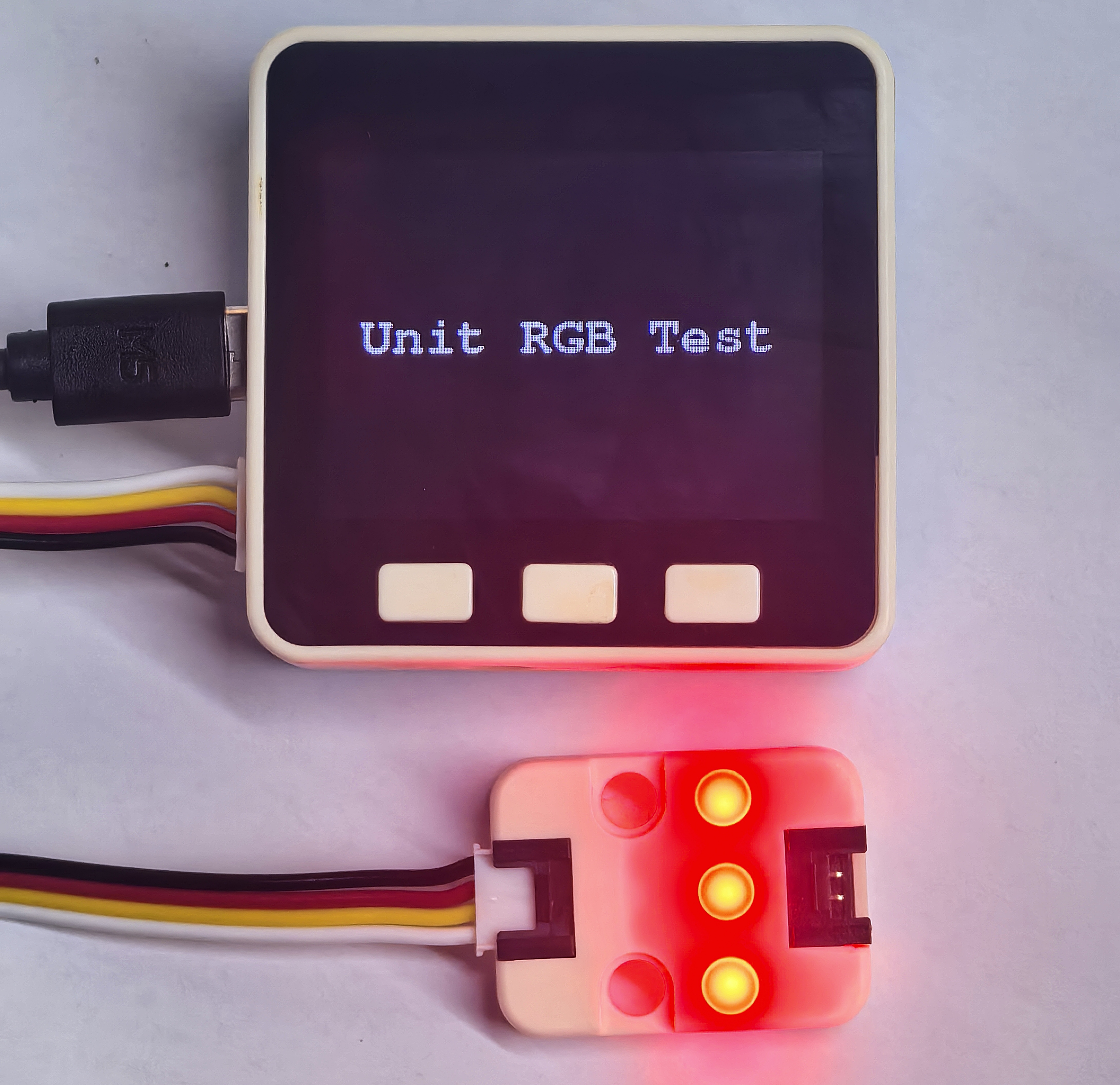
Unit RGB
M5GOでUnit RGBを制御し、様々なライトのサンプルプログラム。
サンプルプログラム
#include <M5Unified.h>
#include <Adafruit_NeoPixel.h>

#define LED_PIN    32
#define NUM_LEDS   3

Adafruit_NeoPixel strip(NUM_LEDS, LED_PIN, NEO_GRB + NEO_KHZ800);

void setup() {
  auto cfg = M5.config();
  M5.begin(cfg);
  M5.Display.setTextDatum(middle_center);
  M5.Display.setTextFont(&fonts::Orbitron_Light_24);
  M5.Display.setTextSize(1);
  M5.Display.drawString("RGB LED Test", M5.Display.width() / 2, M5.Display.height() / 2);
  strip.begin();
  strip.show();
}

void loop() {
    //RED
    for(char i = 0; i <= NUM_LEDS; i++)
    {strip.setPixelColor(i, strip.Color(255, 0, 0)); }
    strip.show();
    delay(1000);

    //GREEN
    for(char i = 0; i <= NUM_LEDS; i++)
    {strip.setPixelColor(i, strip.Color(0, 255, 0)); }
    strip.show();
    delay(1000);

    //BLUE
    for(char i = 0; i <= NUM_LEDS; i++)
    {strip.setPixelColor(i, strip.Color(0, 0, 255)); }
    strip.show();
    delay(1000);
} 動作例: