

Arduino Quick Start
2. Devices & Examples
3. M5Unified
4. M5GFX
5. Extensions
Unit
Atomic
Tab5
IoT
Accessories
Unit UHF-RFID Arduino Tutorial
1. Preparations
- Environment Configuration: Refer to Arduino IDE Getting Started Tutorial to complete IDE installation, and install corresponding board manager and required driver libraries according to the development board being used.
- Required Driver Libraries:
Note
You need to download the latest library version from GitHub: M5Unit-UHF-RFID - M5Stack GitHub. Do not download from Arduino Library. (For any questions, please refer to this tutorial)
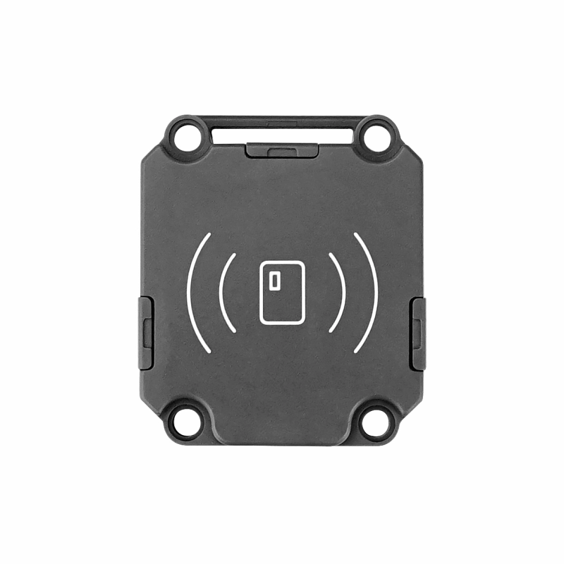
- Required Hardware Products:

2. Notes
Tag Recognition
The package includes an RFID tag for testing. If you need to use other tags, you only need to find tags with EPCglobal UHF Class 1 Gen 2 or ISO 18000-6C protocol.
Pin Compatibility
Due to variations in pin configurations across different host devices, please consult the Pin Compatibility Table in the product documentation prior to use. Modify the sample program according to your specific pin connections.
3. Sample Program
- The main control device used in this tutorial is CoreS3, paired with Unit UHF-RFID. This RF reader/writer module communicates via serial port. Modify the pin definitions in the program according to the actual circuit connections. The corresponding serial port IOs after device connection are
G1 (RX)andG2 (TX).
cpp
1 2 3 4 5 6 7 8 9 10 11 12 13 14 15 16 17 18 19 20 21 22 23 24 25 26 27 28 29 30 31 32 33 34 35 36 37 38 39 40 41 42 43 44 45 46 47 48 49 50 51 52 53 54 55 56 57 58 59 60 61 62 63 64 65 66 67 68 69 70 71 72 73 74 75 76 77 78 79 80 81 82 83 84 85 86 87 88 89 90 91 92
/*
 * SPDX-FileCopyrightText: 2025 M5Stack Technology CO LTD
 *
 * SPDX-License-Identifier: MIT
 */

#include <M5Unified.h>
#include <M5GFX.h>
#include "UNIT_UHF_RFID.h"

M5GFX display;
Unit_UHF_RFID uhf;
String info = "";

void setup() {
    M5.begin();
    Serial.begin(115200);
    uhf.begin(&Serial2, 115200, 1, 2, false);
    while (1) {
        info = uhf.getVersion();
        if (info != "ERROR") {
            Serial.println(info);
            break;
        }
    }
    uhf.setTxPower(2600);
    M5.Display.fillRect(0, 0, 320, 240, WHITE);
    M5.Display.setTextColor(BLACK);
    M5.Display.setFont(&fonts::FreeMonoBold9pt7b);
    M5.Display.setCursor(0, 0);
    M5.Display.println("Unit RFID UHF init...");
}

uint8_t write_buffer[]  = {0xab, 0xcd, 0xef, 0xdd};
uint8_t reade_buffer[4] = {0};

void log(String info) {
    Serial.println(info);
    M5.Display.println(info);
}

void loop() {
        log("polling once");
        uint8_t result = uhf.pollingOnce();
        // result = pollingMultiple(uint16_t polling_count);  Can be scanned repeatedly multiple times.
        Serial.printf("scan result: %d\r\n", result);
        if (result > 0) {
            for (uint8_t i = 0; i < result; i++) {
                log("pc: " + uhf.cards[i].pc_str);
                log("rssi: " + uhf.cards[i].rssi_str);
                log("epc: " + uhf.cards[i].epc_str);
                log("-----------------");
                delay(10);
            }
        }
        delay(2000);
        M5.Display.fillScreen(WHITE);
        M5.Display.setCursor(0, 0);

        if (uhf.select(uhf.cards[0].epc)) {
            log("Select OK");
        } else {
            log("Select ERROR");
        }
        log("Current Select EPC:");
        log(uhf.selectInfo());
        delay(2000);
        M5.Display.fillScreen(WHITE);
        M5.Display.setCursor(0, 0);

        log("Write Data...");
        if (uhf.writeCard(write_buffer, sizeof(write_buffer), 0x04, 0, 0x00000000)) {
            log("Write OK");
        } else {
            log("Write ERROR");
        }
        delay(1000);
        log("Read Data...");
        if (uhf.readCard(reade_buffer, sizeof(reade_buffer), 0x04, 0, 0x00000000)) {
            log("Read OK");
            log("Data Content");
            for (uint8_t i = 0; i < sizeof(reade_buffer); i++) {
                Serial.printf("%x", reade_buffer[i]);
                M5.Display.printf("%x", reade_buffer[i]);
            }
        } else {
            log("Read ERROR");
        }
        delay(2000);
        M5.Display.fillScreen(WHITE);
        M5.Display.setCursor(0, 0);
}4. Compile and Upload
Download Mode: Different devices need to enter download mode before program burning, and this step may vary depending on the main control device. For details, please refer to the device program download tutorial list at the bottom of the Arduino IDE Getting Started Tutorial page for specific operation methods.
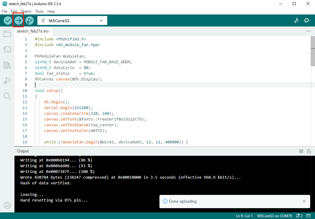
For CoreS3, press and hold the reset button (about 2 seconds) until the internal green LED lights up, then release. The device will now enter download mode and wait for burning.
.gif)
- Select the device port, click the compile and upload button in the upper left corner of Arduino IDE, and wait for the program to complete compilation and upload to the device.
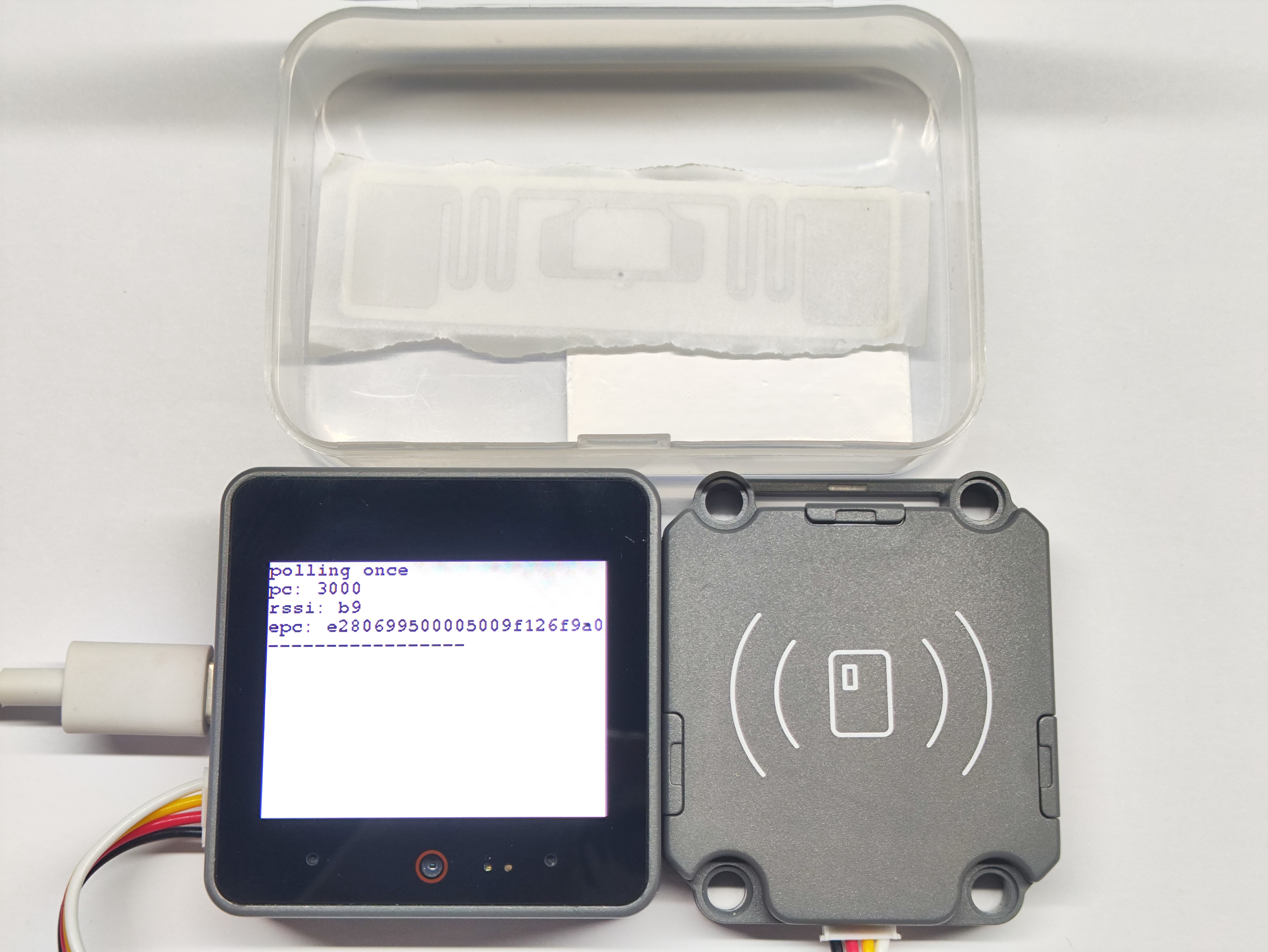
5. Tag Recognition
- The program starts with a scanning phase. If the scan is successful, the RFID tag's protocol control word, received signal strength indicator, and electronic product code will be displayed on the screen.
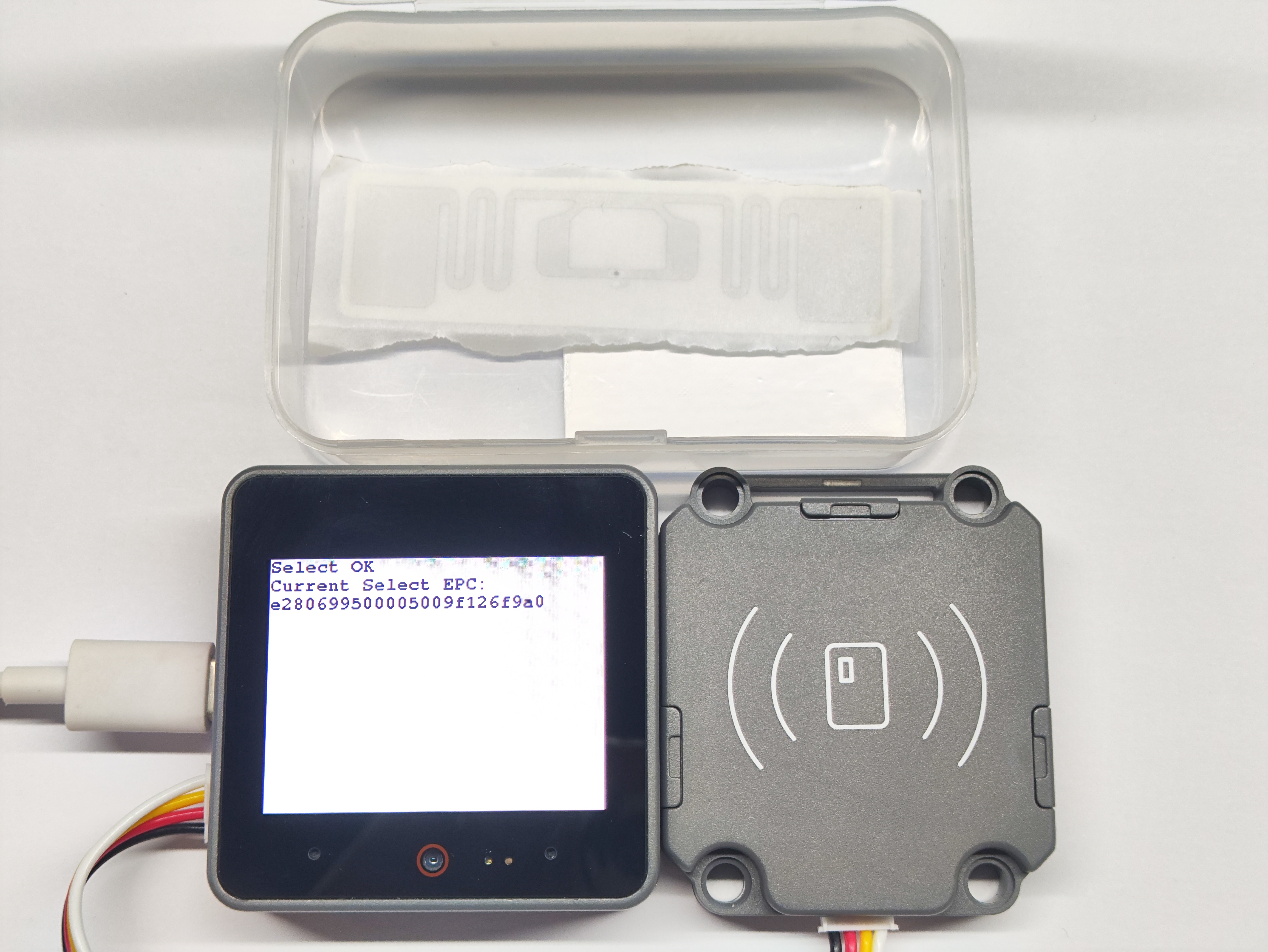
- When multiple tags are present, the RFID module supports selection function. After successful selection, the electronic code of the tag will be displayed.
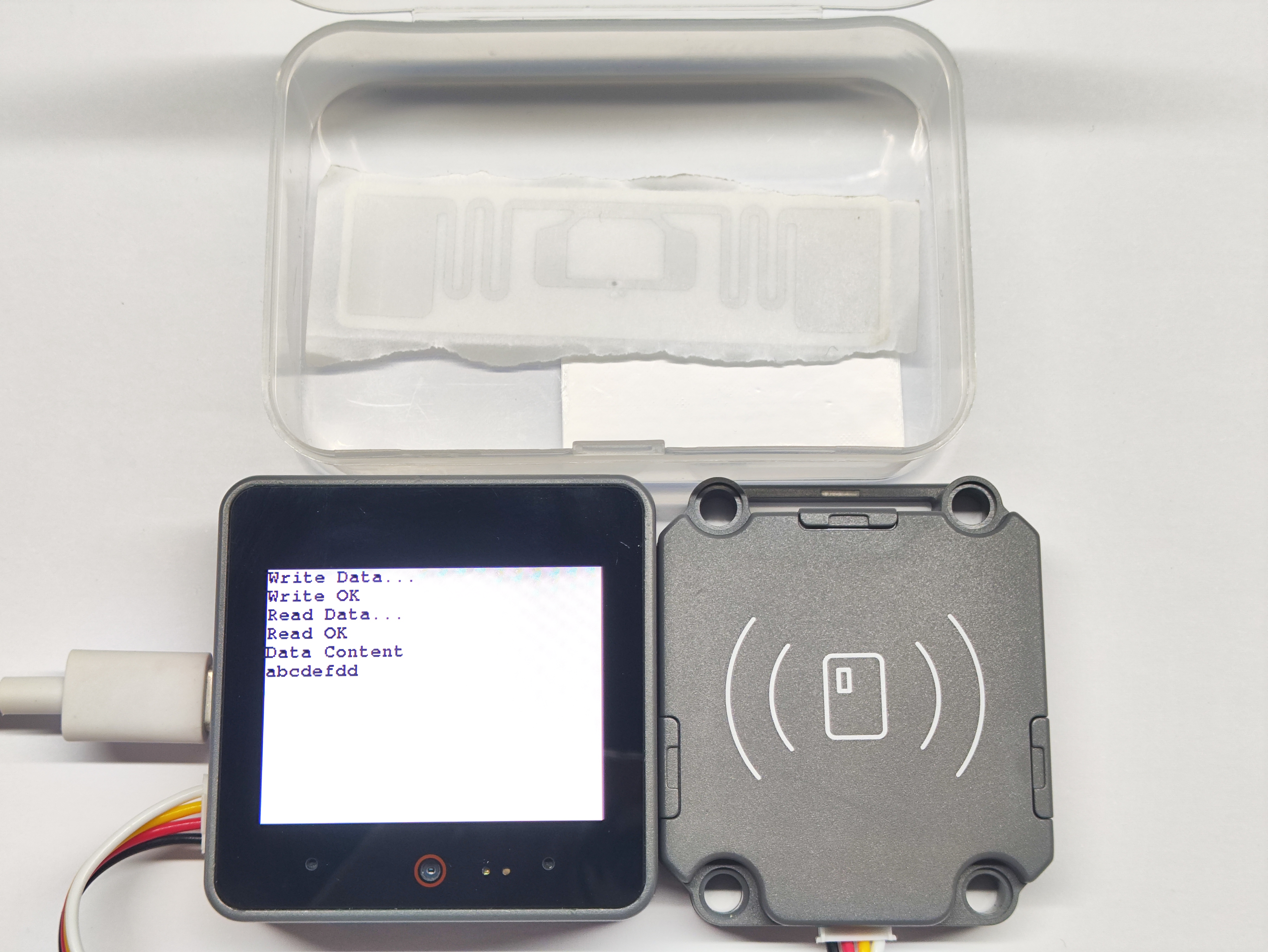
- The RFID module can directly read/write the tag's memory area. A successful write will display "Write OK", and a successful read will display "Read OK" and output the newly written data.
Page Tools