Arduino入門
2. デバイス&サンプル
3. M5Unified
4. M5GFX
5. 拡張モジュール&サンプル
Unit
Base
IoT
6. アプリケーション
AWS IoT Core
Unit Glass2 Arduino 使用ガイド
1.準備作業
- 環境設定:Arduino IDE 入門ガイド を参考にして IDE のインストールを完了させてください。使用する開発ボードに応じて、対応するボードパッケージと必要なドライバライブラリをインストールします。
- 使用するドライバライブラリ:
- 使用するハードウェア製品:


2.サンプルプログラム
コンパイル要件
M5Stack ボードマネージャ バージョン >= 3.2.2
M5Unified ライブラリ バージョン >= 0.2.7
M5GFX ライブラリ バージョン >= 0.2.9
M5Unified ライブラリ バージョン >= 0.2.7
M5GFX ライブラリ バージョン >= 0.2.9
cpp
1 2 3 4 5 6 7 8 9 10 11 12 13 14 15 16 17 18 19 20 21 22 23 24 25 26 27 28 29 30 31 32 33 34 35 36 37 38
#include <M5UnitGLASS2.h>
#include <M5Unified.h>

#define M5UNITGLASS2_ADDR 0x3C  // For Unit Glass2, 0x3C is default, and 0x3D is modified.

int index_unit_glass2;

void setup() {
  auto cfg = M5.config();
  cfg.external_display.unit_glass2 = true;
  M5.begin(cfg);

  index_unit_glass2 = M5.getDisplayIndex(m5::board_t::board_M5UnitGLASS2);
  M5.Displays(index_unit_glass2).setTextSize(2);
  M5.Displays(index_unit_glass2).clear();
}

void loop() {
  M5.Displays(index_unit_glass2).setCursor(0, 0);
  M5.Displays(index_unit_glass2).print("This is \nUnit \nGlass2");
  delay(1000);
  M5.Displays(index_unit_glass2).clear();

  M5.Displays(index_unit_glass2).drawRect(0, 0, 128, 64, 0xFFFF);  // x, y, w, h, color
  delay(500);
  M5.Displays(index_unit_glass2).drawCircle(20, 20, 15, 0xFFFF);  // x, y, r, color
  delay(500);
  M5.Displays(index_unit_glass2).fillArc(50, 45, 17, 20, 100, 330, 0xFFFF);  // x, y, r0, r1, angle0, angle1, color
  delay(500);
  M5.Displays(index_unit_glass2).fillRect(45, 10, 25, 10, 0xFFFF);  // x, y, w, h, color
  delay(500);
  M5.Displays(index_unit_glass2).fillTriangle(90, 10, 80, 40, 110, 55, 0xFFFF);  // x0, y0, x1, y1, x2, y2, color
  delay(500);
  M5.Displays(index_unit_glass2).drawLine(110, 0, 128, 64, 0xFFFF);  // x0, y0, x1, y1, color
  delay(1000);

  M5.Displays(index_unit_glass2).clear();
}実行効果:
3.I2C アドレスの変更

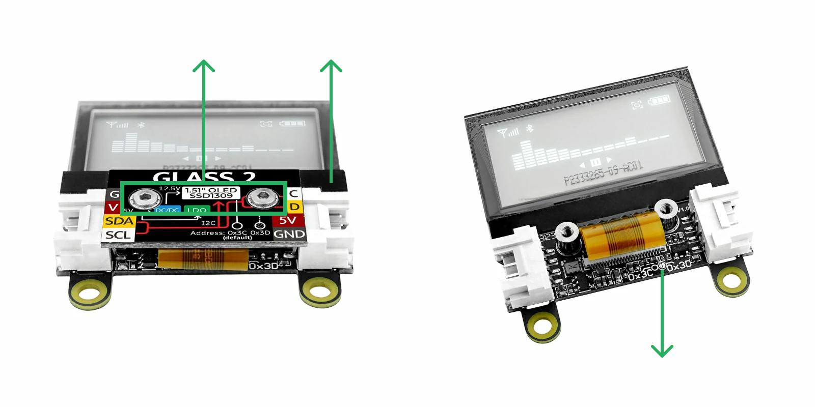
上図のように、六角レンチを使って 2 本のネジを外し、上にカバーを取り外します。ディスプレイのフラットケーブルをそっと押しのけると、円の中にある 2 つの半円形パッドが見えます。これらのパッドをハンダで接続すると、I2C アドレスは 0x3D に変更されます。ハンダを除去すれば、デフォルトの 0x3C に戻すことができます。
I2C アドレスを 0x3D に変更した場合は、プログラム内にマクロ定義 #define M5UNITGLASS2_ADDR 0x3D を追加する必要があります。2 つの HY2.0-4P Grove ポートは内部で接続されており、どちらを使用しても問題ありません。他の I2C デバイスの接続に使用できます。