Arduino Quick Start
2. Devices & Examples
3. M5Unified
4. M5GFX
5. Extensions
Unit
Base
IoT
Accessories
Unit EXT.IO2 Arduino Tutorial
1. Preparations
- Environment Setup: Refer to the Arduino IDE Getting Started Guide to complete IDE installation, and install the corresponding board manager and required driver libraries based on the development board being used.
- Required Driver Libraries:
- Required Hardware Products:

2. Notes
3. Example Program
The main controller device used in this tutorial is CoreS3 with Unit EXT.IO2. This IO expansion unit communicates via I2C protocol. Modify the pin definitions in the program according to the actual circuit connections. After device connection, the corresponding communication IOs are
G1 (SDA)andG2 (SCL).Analog ADC Input Pins
#include <M5Unified.h>
#include "M5_EXTIO2.h"
M5_EXTIO2 extio;
void setup() {
M5.begin();
Serial.begin(115200);
M5.Display.fillScreen(WHITE);
M5.Display.setTextColor(BLACK);
M5.Display.setTextFont(&fonts::FreeMonoBold9pt7b);
M5.Display.setCursor(0, 0);
while (!extio.begin(&Wire, 2, 1,
0x45)) {
Serial.println("extio Connect Error");
M5.Display.println("extio Connect Error");
delay(100);
}
extio.setAllPinMode(ADC_INPUT_MODE); // Set all pins to ADC input mode.
}
char info[50];
void loop() {
M5.Display.fillScreen(WHITE);
M5.Display.setCursor(0, 0);
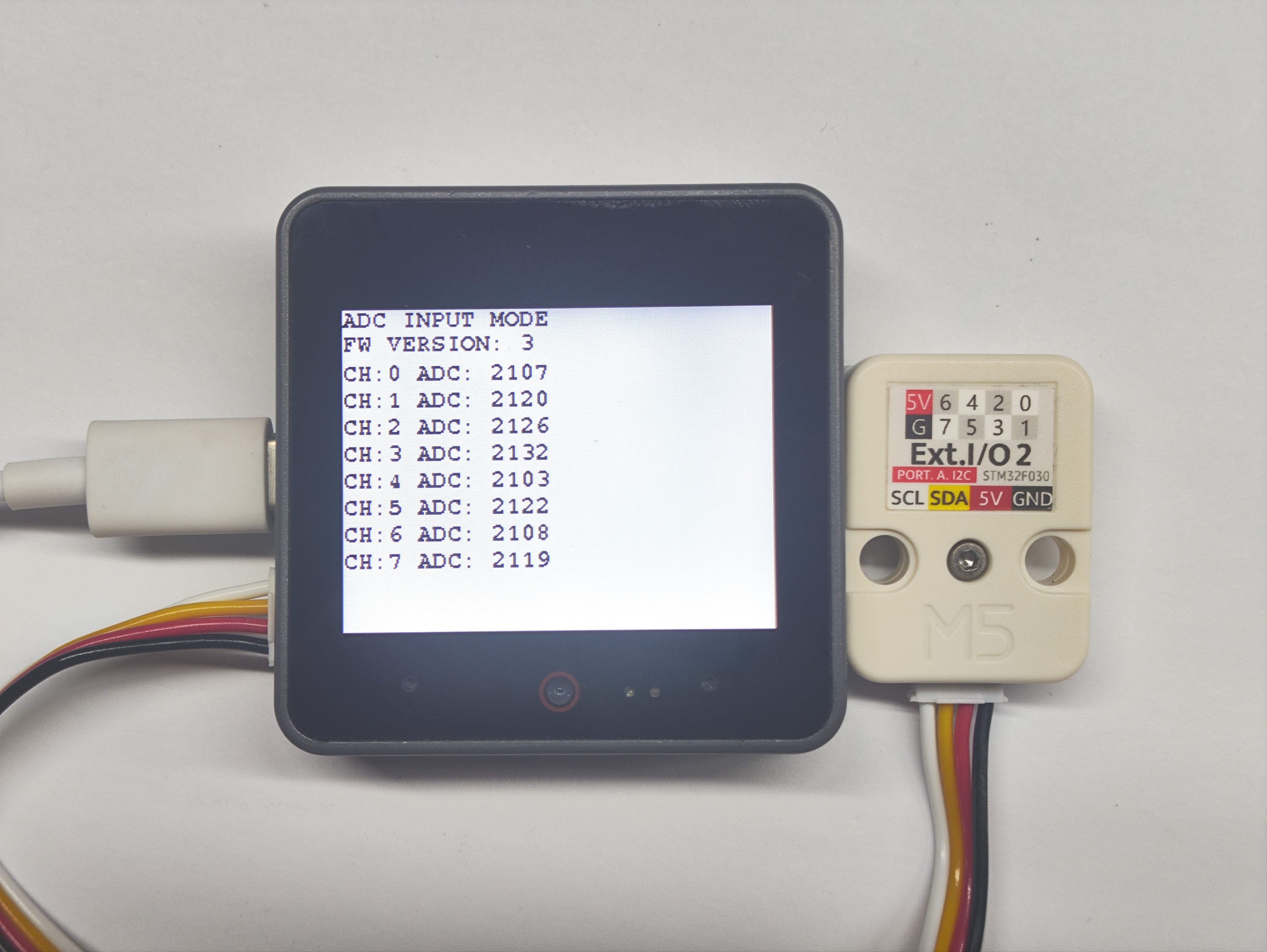
M5.Display.println("ADC INPUT MODE");
M5.Display.println("FW VERSION: " + String(extio.getVersion()));
for (uint8_t i = 0; i < 8; i++) {
uint16_t adc =
extio.getAnalogInput(i, _12bit); // Get ADC value.
Serial.printf("CH:%d ADC: %d", i, adc);
M5.Display.fillRect(0, i * 20 + 40, 200, 15, WHITE);
M5.Display.setCursor(0, i * 20 + 40);
M5.Display.printf("CH:%d ADC: %d", i, adc);
}
vTaskDelay(1000);
}- Digital Output Pins
#include <M5Unified.h>
#include "M5_EXTIO2.h"
M5_EXTIO2 extio;
extio_io_mode_t mode = DIGITAL_OUTPUT_MODE;
void btnTask(void *pvParameters) {
while (1) {
if (M5.BtnA.wasPressed()) {
if (mode == DIGITAL_INPUT_MODE) {
mode = DIGITAL_OUTPUT_MODE;
} else {
mode = DIGITAL_INPUT_MODE;
}
}
M5.update();
vTaskDelay(80);
}
}
void setup() {
M5.begin();
Serial.begin(115200);
M5.Display.fillScreen(WHITE);
M5.Display.setTextColor(BLACK);
M5.Display.setTextFont(&fonts::FreeMonoBold9pt7b);
M5.Display.setCursor(0, 0);
while (!extio.begin(&Wire, 2, 1, 0x45)) {
Serial.println("extio Connect Error");
M5.Display.println("extio Connect Error");
delay(100);
}
extio.setAllPinMode(
DIGITAL_OUTPUT_MODE);
xTaskCreatePinnedToCore(btnTask, "btnTask",
4096,
NULL,
1 ,
NULL, 0);
}
char info[50];
void loop() {
if (mode == DIGITAL_INPUT_MODE) {
M5.Display.fillScreen(WHITE);
M5.Display.setCursor(0, 0);
M5.Display.println("DIGITAL INPUT MODE");
M5.Display.println("FW VERSION: " + String(extio.getVersion()));
for (uint8_t i = 0; i < 8; i++) {
if (extio.getDigitalInput(i)) {
M5.Display.fillRect(i * 30 + 30, 145, 28, 30, WHITE);
} else {
M5.Display.fillRect(i * 30 + 30, 145, 28, 30, WHITE);
}
}
} else if (mode == DIGITAL_OUTPUT_MODE) {
M5.Display.fillScreen(WHITE);
M5.Display.setCursor(0, 0);
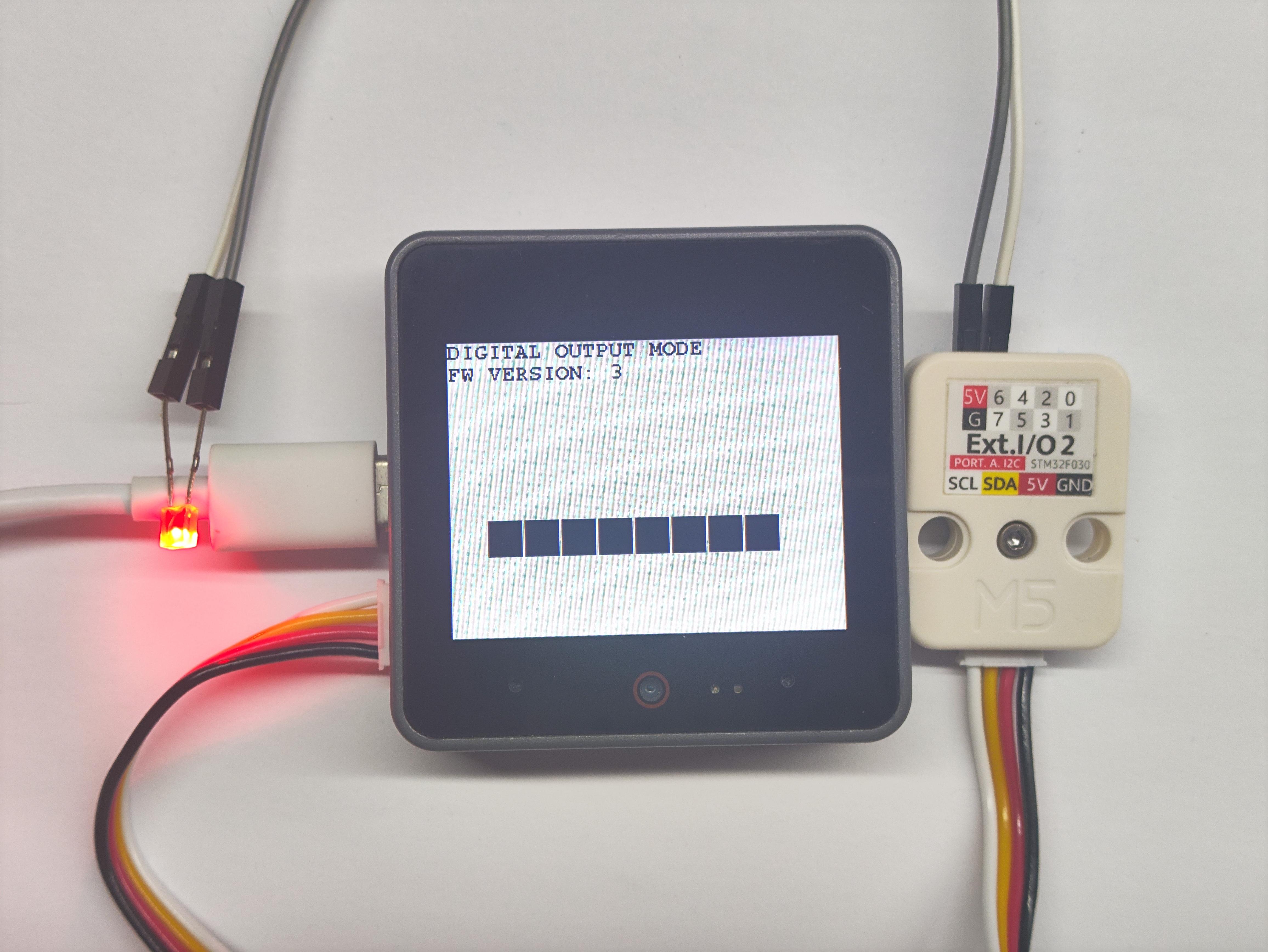
M5.Display.println("DIGITAL OUTPUT MODE");
M5.Display.printf("FW VERSION: %s",String(extio.getVersion()));
for (uint8_t i = 0; i < 8; i++) {
extio.setDigitalOutput(i, HIGH);
M5.Display.fillRect(i * 30 + 30, 145, 28, 30, BLACK);
M5.Display.setCursor(i * 30 + 30, 145);
vTaskDelay(100);
}
for (uint8_t i = 0; i < 8; i++) {
extio.setDigitalOutput(i, LOW);
M5.Display.fillRect(i * 30 + 30, 145, 28, 30, BLACK);
M5.Display.setCursor(i * 30 + 30, 145);
vTaskDelay(100);
}
}
extio.setAllPinMode(mode);
vTaskDelay(100);
}- Digital Input Pins
#include <M5Unified.h>
#include "M5_EXTIO2.h"
M5_EXTIO2 extio;
extio_io_mode_t mode = DIGITAL_OUTPUT_MODE;
void btnTask(void *pvParameters) {
while (1) {
if (M5.BtnA.wasPressed()) {
if (mode == DIGITAL_INPUT_MODE) {
mode = DIGITAL_OUTPUT_MODE;
} else {
mode = DIGITAL_INPUT_MODE;
}
}
M5.update();
vTaskDelay(80);
}
}
void setup() {
M5.begin();
Serial.begin(115200);
M5.Display.fillScreen(WHITE);
M5.Display.setTextColor(BLACK);
M5.Display.setTextFont(&fonts::FreeMonoBold9pt7b);
M5.Display.setCursor(0, 0);
while (!extio.begin(&Wire, 2, 1, 0x45)) {
Serial.println("extio Connect Error");
M5.Display.println("extio Connect Error");
delay(100);
}
extio.setAllPinMode(
DIGITAL_OUTPUT_MODE);
xTaskCreatePinnedToCore(btnTask, "btnTask",
4096,
NULL,
1 ,
NULL, 0);
}
char info[50];
void loop() {
M5.Display.fillScreen(WHITE);
M5.Display.setCursor(0, 0);
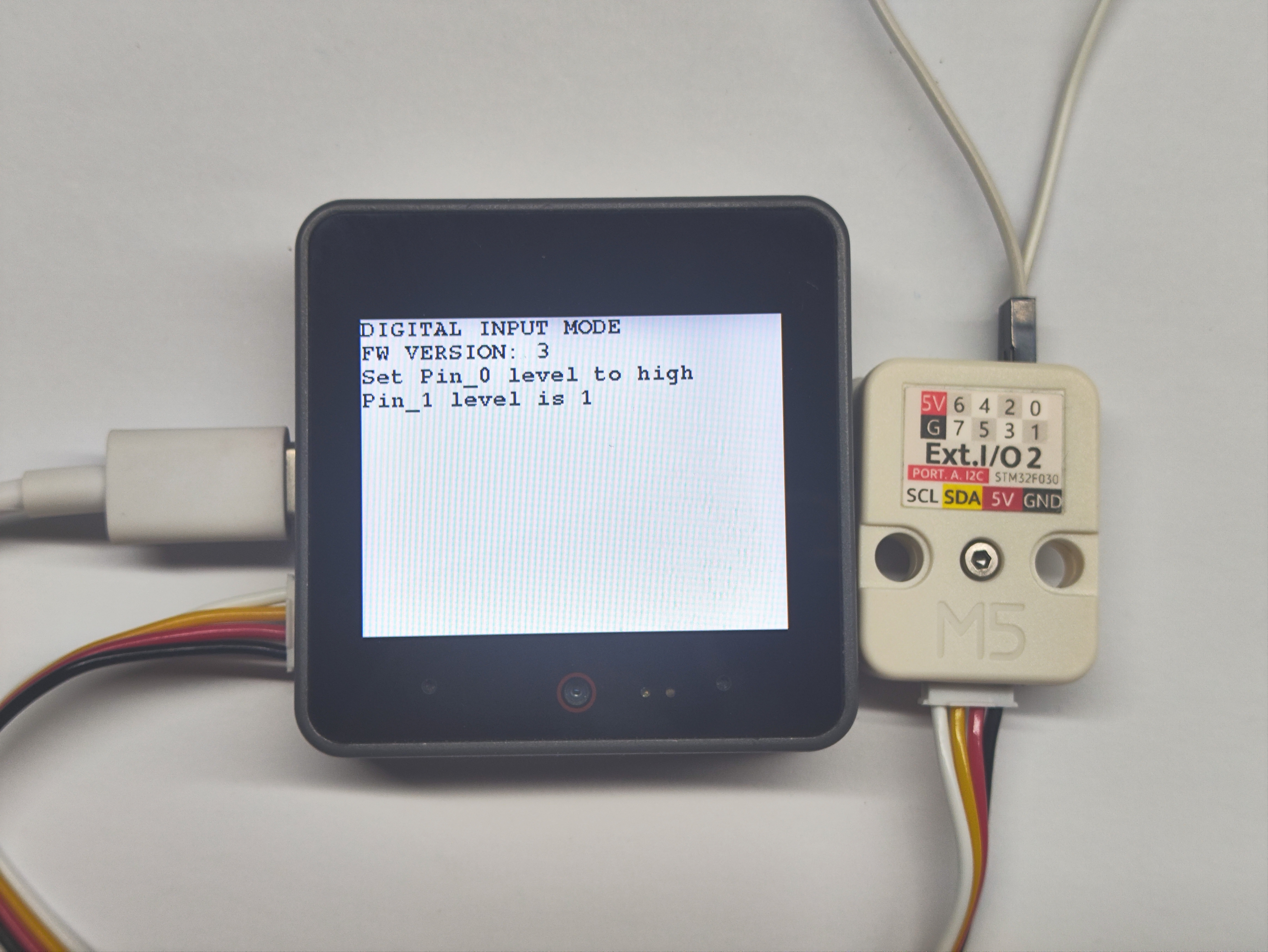
M5.Display.println("DIGITAL INPUT MODE");
M5.Display.println("FW VERSION: " + String(extio.getVersion()));
extio.setDigitalOutput(0, HIGH);
M5.Display.println("Set Pin_0 level to high");
M5.Display.printf("Pin_1 level is %s",(String)extio.getDigitalInput(1));
extio.setAllPinMode(mode);
vTaskDelay(100);
}- SERVO Control
#include <M5Unified.h>
#include "M5_EXTIO2.h"
M5_EXTIO2 extio;
void setup() {
M5.begin();
Serial.begin(115200);
M5.Display.fillScreen(WHITE);
M5.Display.setTextColor(BLACK);
M5.Display.setTextFont(&fonts::FreeMonoBold9pt7b);
M5.Display.setCursor(0, 0);
while (!extio.begin(&Wire, 2, 1, 0x45)) {
Serial.println("extio Connect Error");
M5.Display.println("extio Connect Error");
delay(100);
}
extio.setAllPinMode(SERVO_CTL_MODE);
}
char info[50];
void loop() {
M5.Display.fillScreen(WHITE);
M5.Display.setCursor(0, 0);
M5.Display.println("SERVO CTL MODE");
M5.Display.printf("FW VERSION: %s", String(extio.getVersion()));
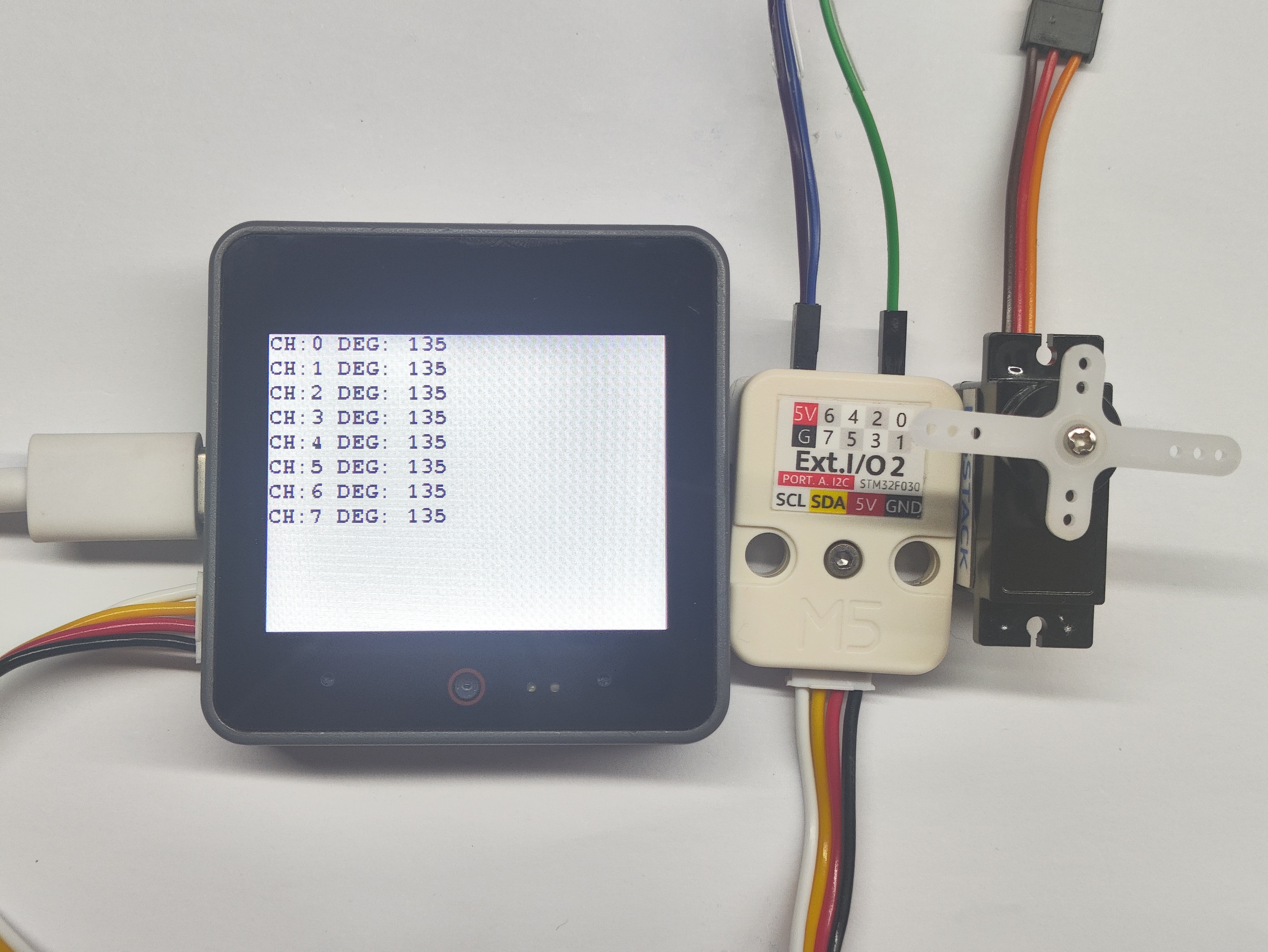
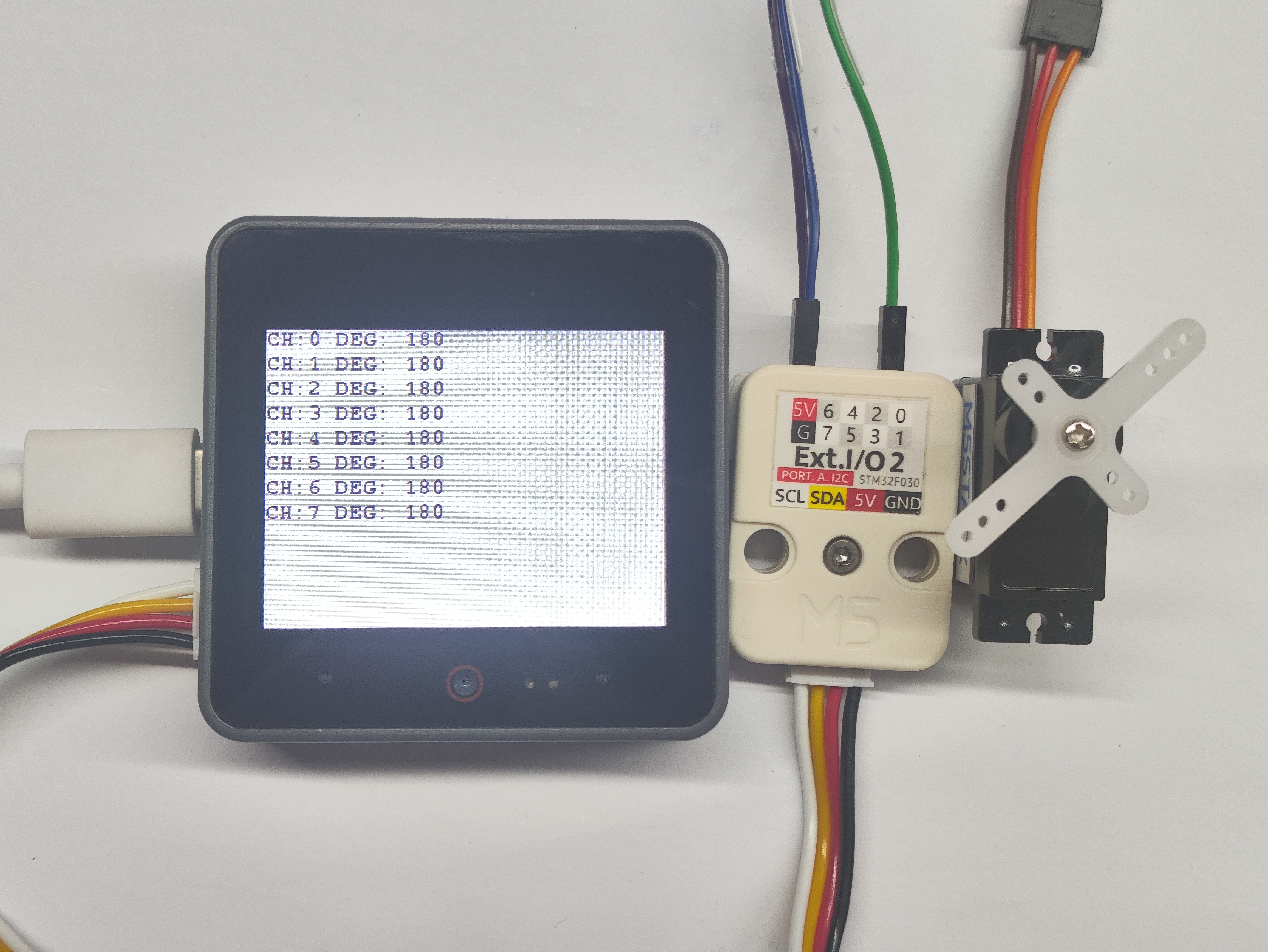
for (uint8_t deg = 0; deg <= 180; deg += 45) {
for (uint8_t i = 0; i < 8; i++) {
extio.setServoAngle(i, deg);
Serial.printf("CH:%d DEG: %d", i, deg);
M5.Display.fillRect(0, i * 20, 200, i * 20 + 20, WHITE);
M5.Display.setCursor(0, i * 20);
M5.Display.printf("CH:%d DEG: %d", i, deg);
}
vTaskDelay(500);
}
for (int pulse = 500; pulse <= 2500; pulse += 100) {
for (uint8_t i = 0; i < 8; i++) {
extio.setServoPulse(i, pulse);
Serial.printf("CH:%d P: %d", i, pulse);
M5.Display.fillRect(0, i * 20, 200, i * 20 + 20, WHITE);
M5.Display.setCursor(0, i * 20);
M5.Display.printf("CH:%d P: %d", i, pulse);
}
vTaskDelay(500);
}
delay(100);
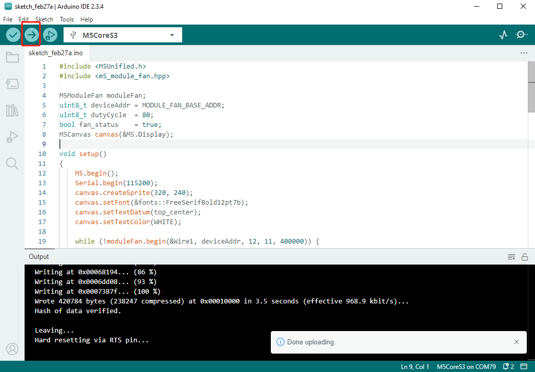
}4. Compile and Upload
Download Mode: Different devices need to enter download mode before programming. This process may vary depending on the main controller. For details, please refer to the device programming tutorial list at the bottom of the Arduino IDE Getting Started Guide page.
For CoreS3: Press and hold the reset button (about 2 seconds) until the internal green LED lights up, then release. The device will enter download mode and wait for programming.
.gif)
- Select the device port and click the compile/upload button in the top-left corner of Arduino IDE. Wait for the program to complete compilation and upload to the device.
5. Extended Effects
- In ADC_INPUT mode, analog values from each channel can be read.
- In digital output mode, connect an LED to visualize the pin's level changes.
- In digital input mode, one pin outputs high level and another pin reads it to determine the level state.
- In SERVO mode, the pin can output a PWM signal to drive a servo.