Unit RF433 Arduino 使用チュートリアル
1. 準備作業
環境設定: Arduino IDE 入門チュートリアルを参照して IDE のインストールを完了し、使用する開発ボードに応じたボード管理と必要なドライバライブラリをインストールしてください。
使用するドライバライブラリ:
Note
You need to download the latest library version from GitHub: RF433any - GitHub. Do not download from Arduino Library. (For any questions, please refer to this tutorial)
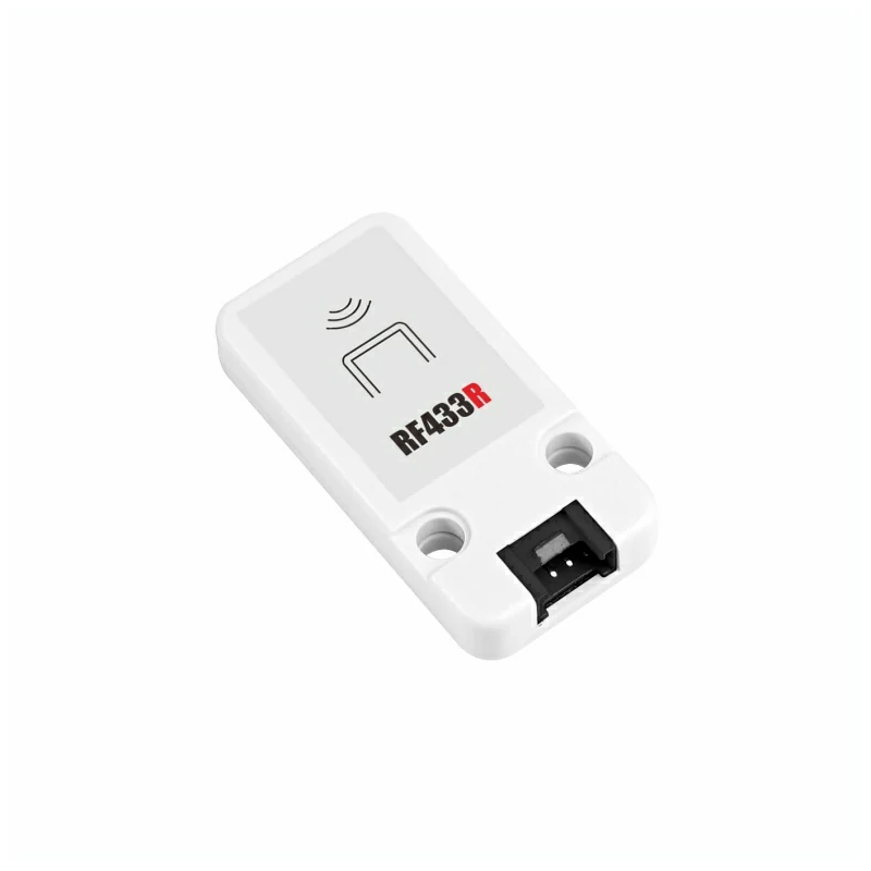
- 使用するハードウェア製品:
2. 注意事項
送受信セット
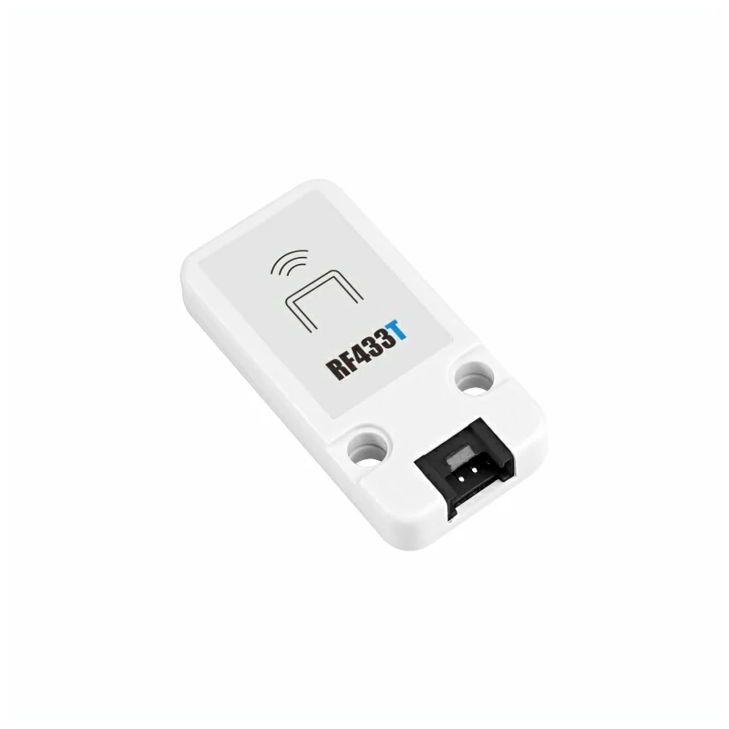
この RF433 装置はペアで使用する必要があり、送信モジュールとして Unit RF433T 1 台、受信モジュールとして Unit RF433R 1 台が必要です。
ピン互換性
各ホストデバイスのピン構成が異なるため、使用前に製品ドキュメントの RF433T ピン互換表と RF433R ピン互換表を参照し、実際のピン接続に応じてサンプルプログラムを修正してください。
3. サンプルプログラム
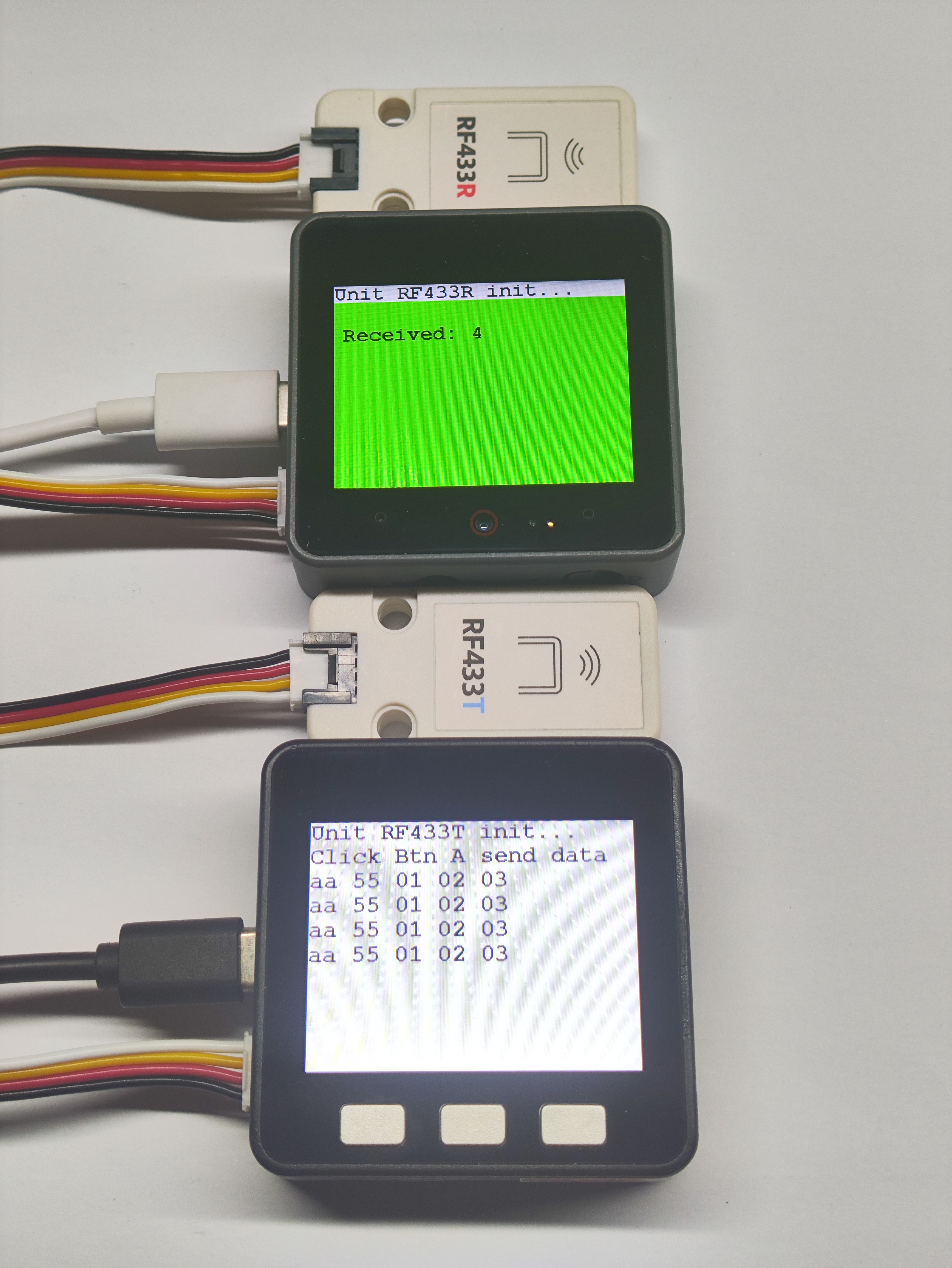
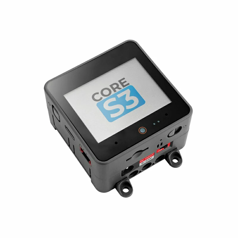
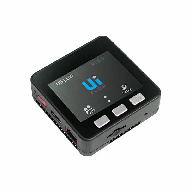
- 本チュートリアルでは、Basic v2.7 と Unit RF433T を送信端、CoreS3 と Unit RF433R を受信端として使用します。モジュールには DOUT と DIN の 2 種類の回路接続方式がありますので、実際の接続に応じてプログラム内のピン定義を修正してください。
3.1 RF433T 送信端
cpp
1 2 3 4 5 6 7 8 9 10 11 12 13 14 15 16 17 18 19 20 21 22 23 24 25 26 27 28 29 30 31 32 33 34 35 36 37 38 39 40 41 42 43 44 45 46 47 48 49 50 51 52 53 54 55 56 57 58 59 60 61 62 63 64 65 66 67 68 69 70 71 72 73 74 75 76 77 78 79 80
#include <M5Unified.h>

#define TX_PIN 21

uint8_t data[5] = {0xAA, 0x55, 0x01, 0x02, 0x03};

void pulse(int high, int low) {
    digitalWrite(TX_PIN, HIGH);
    delayMicroseconds(high);
    digitalWrite(TX_PIN, LOW);
    delayMicroseconds(low);
}

void sendCorrected() {
    noInterrupts();

    digitalWrite(TX_PIN, LOW);
    delayMicroseconds(10000);

    pulse(5000, 2500);
    pulse(2500, 1250);

    pulse(8000, 4000);

    for (int byte = 0; byte < 5; byte++) {
        for (int bit = 7; bit >= 0; bit--) {
            if (data[byte] & (1 << bit)) {
                pulse(600, 300);
            } else {
                pulse(300, 600);
            }
        }
    }

    pulse(8000, 10000);

    interrupts();
}

void setup() {
    M5.begin();
    Serial.begin(115200);

    pinMode(TX_PIN, OUTPUT);
    digitalWrite(TX_PIN, LOW);

    M5.Display.fillRect(0, 0, 320, 240, WHITE);
    M5.Display.setTextColor(BLACK);
    M5.Display.setFont(&fonts::FreeMonoBold12pt7b);
    M5.Display.setCursor(0, 0);
    M5.Display.println("Corrected RF433T");
    M5.Display.println("Click Btn A to send");

    Serial.println("Corrected RF433 Transmitter Ready");
}

void loop() {
    M5.update();

    if (M5.BtnA.wasPressed()) {
        Serial.println("SEND CORRECTED");

        sendCorrected();
        delay(100);

        Serial.print("Sent: ");
        for (int i = 0; i < 5; i++) {
            Serial.printf("%02X ", data[i]);
        }
        Serial.println();

        M5.Display.print("Sent: ");
        for (int i = 0; i < 5; i++) {
            M5.Display.printf("%02X ", data[i]);
        }
        M5.Display.println("");
    }

    delay(10);
}3.2 RF433R 受信端
cpp
1 2 3 4 5 6 7 8 9 10 11 12 13 14 15 16 17 18 19 20 21 22 23 24 25 26 27 28 29 30 31 32 33 34 35 36 37 38 39 40 41 42 43 44 45 46 47 48 49 50 51 52 53 54 55 56 57 58
#include "RF433any.h"
#include <M5Unified.h>

#define PIN_RFINPUT  1

void setup() {
    M5.begin();
    M5.Display.fillRect(0, 0, 320, 240, WHITE);
    M5.Display.setTextColor(BLACK);
    M5.Display.setFont(&fonts::FreeMonoBold12pt7b);
    M5.Display.setCursor(0, 0);
    M5.Display.println("RF433 Receiver");
    pinMode(PIN_RFINPUT, INPUT);
    Serial.begin(115200);
    Serial.println("Waiting for signal\n");
    M5.Display.println("Waiting for signal");
}

Track track(PIN_RFINPUT);

void loop() {
    track.treset();

    while (!track.do_events())
        delay(1);

    Decoder *pdec0 = track.get_data(
        RF433ANY_FD_DECODED | RF433ANY_FD_DEDUP | RF433ANY_FD_NO_ERROR
    );
    for (Decoder *pdec = pdec0; pdec != nullptr; pdec = pdec->get_next()) {
        Serial.print("Received ");
        M5.Display.println("Received \r\n");
        Serial.print(pdec->get_nb_bits());
        M5.Display.print(pdec->get_nb_bits());
        Serial.print(" bits (x");
        M5.Display.println(" bits (x");
        Serial.print(pdec->get_repeats() + 1);
        M5.Display.print(pdec->get_repeats() + 1);
        Serial.print("): ");
        M5.Display.println(": ");
        char *buf = pdec->get_pdata()->to_str();
            // DEFENSIVE PROGRAMMING
            //   The option RF433ANY_FD_DECODED above guarantees there's always
            //   something decoded. Test done though, just in case.
        if (buf) {
            Serial.println(buf);
            M5.Display.println(buf);
            free(buf);
        }
    }
    delete pdec0;
    delay(2000);
    M5.Display.fillRect(0, 40, 320, 220, WHITE);
    M5.Display.setCursor(0, 40);
}

// vim: ts=4:sw=4:tw=80:et
4. コンパイルとアップロード
ダウンロードモード:デバイスによってプログラム書き込み前にダウンロードモードに入る必要があります。この手順はメインコントローラデバイスによって異なる場合があります。詳細はArduino IDE 入門チュートリアルページ下部のデバイスプログラミングチュートリアルリストを参照してください。
CoreS3 の場合:リセットボタンを約 2 秒間長押しし、内部の緑色 LED が点灯したら離します。これでデバイスはダウンロードモードに入り、書き込みを待機します。
.gif)
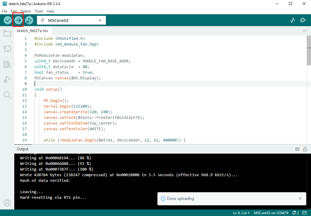
- デバイスポートを選択し、Arduino IDE 左上のコンパイル/アップロードボタンをクリックします。プログラムのコンパイルが完了し、デバイスにアップロードされるまで待機します。
5. 通信テスト
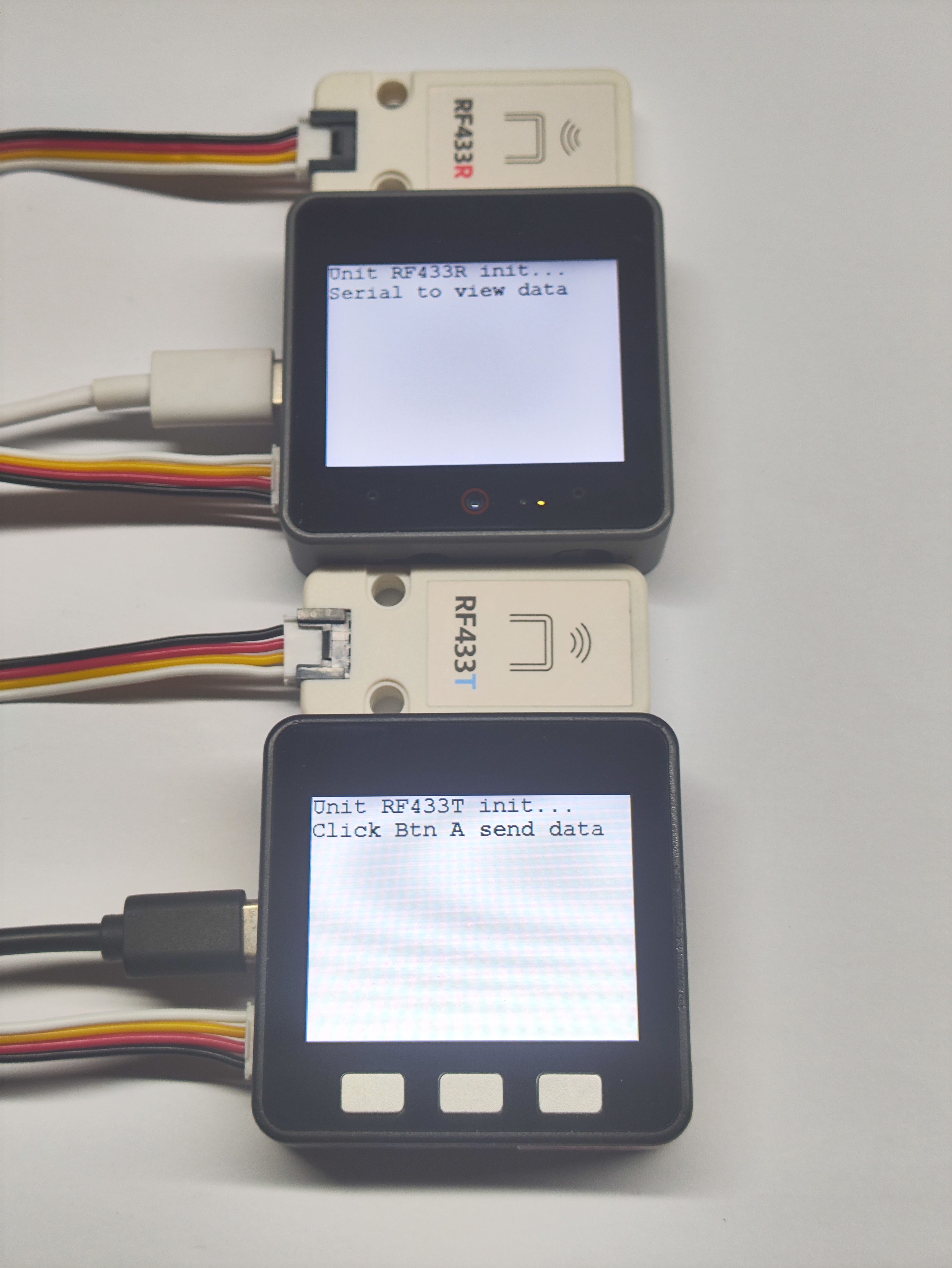
- Basic v2.7 のボタン A を押すと、RF433T 経由でデータパケットが送信されます。CoreS3 が RF433R 経由でデータパケットを受信した場合、シリアルポートに出力され、画面にリアルタイムで表示されます。
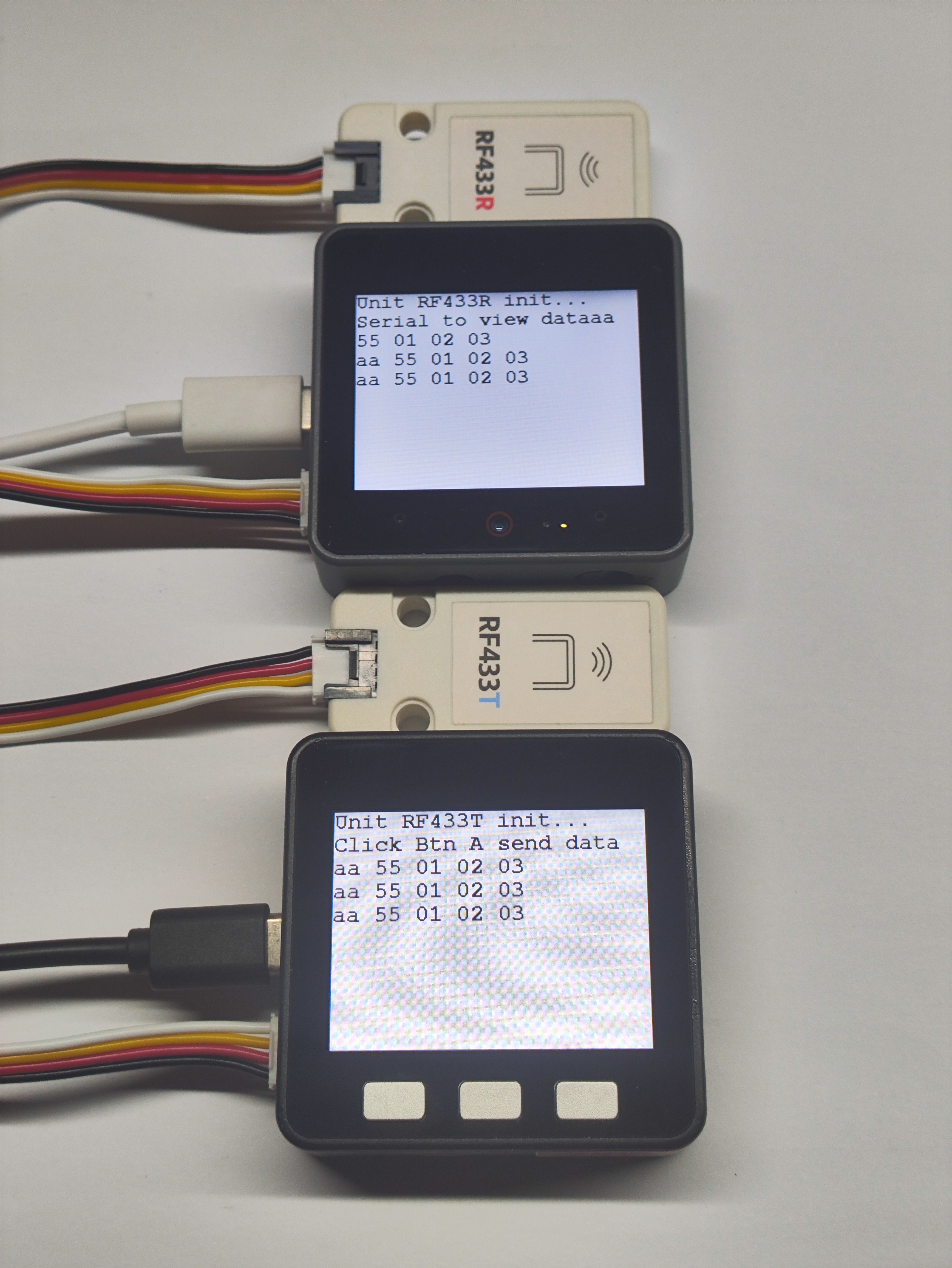
- 2 台のデバイス間で 4 回の通信が成功すると、CoreS3 の画面が緑色に変わり、成功を示します。
