Unit EXT.IO2 Arduino 使用チュートリアル
1. 準備作業
- 環境設定: Arduino IDE 入門チュートリアルを参照して IDE のインストールを完了し、使用する開発ボードに応じたボード管理と必要なドライバライブラリをインストールしてください。
- 使用するドライバライブラリ:
注意
GitHub から最新のライブラリバージョンをダウンロードする必要があります: M5Unit-EXTIO2 - M5Stack GitHub。Arduino ライブラリからダウンロードしないでください。(質問がある場合は、このチュートリアルを参照してください)
- 使用するハードウェア製品:
2. 注意事項
ピン互換性
各ホストデバイスのピン構成が異なるため、使用前に製品ドキュメントのピン互換表を参照し、実際のピン接続に応じてサンプルプログラムを修正してください。
3. サンプルプログラム
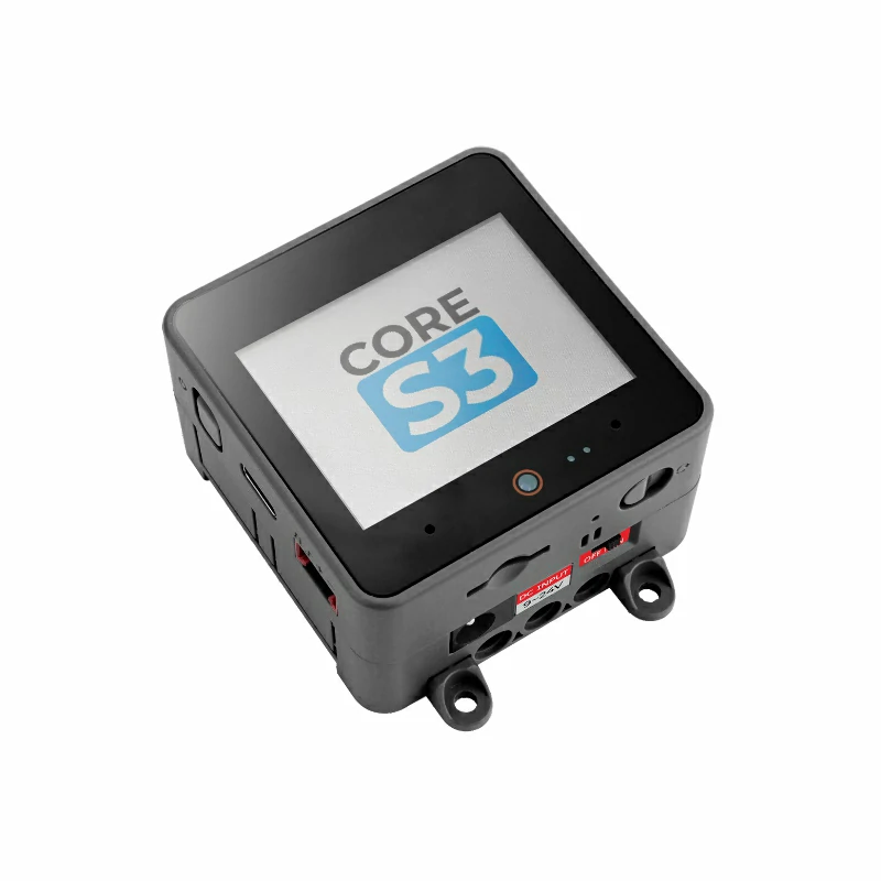
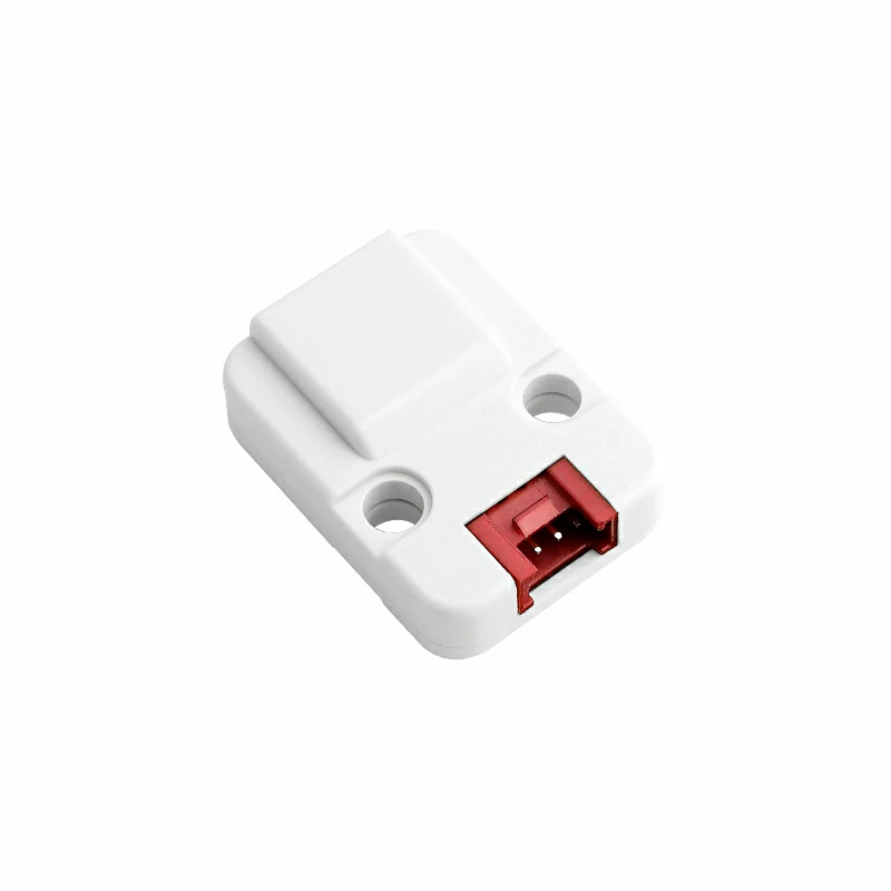
本チュートリアルで使用するメインコントローラデバイスは CoreS3 と Unit EXT.IO2 です。この IO 拡張ユニットは I2C 通信方式を採用しています。実際の回路接続に応じてプログラム内のピン定義を修正してください。デバイス接続後、対応する通信 IO は
G1 (SDA)とG2 (SCL)です。アナログ ADC 入力ピン
cpp
1 2 3 4 5 6 7 8 9 10 11 12 13 14 15 16 17 18 19 20 21 22 23 24 25 26 27 28 29 30 31 32 33 34 35 36 37 38
#include <M5Unified.h>
#include "M5_EXTIO2.h"

M5_EXTIO2 extio;

void setup() {
    M5.begin();
    Serial.begin(115200);
    M5.Display.fillScreen(WHITE);
    M5.Display.setTextColor(BLACK);
    M5.Display.setTextFont(&fonts::FreeMonoBold9pt7b);
    M5.Display.setCursor(0, 0);
    while (!extio.begin(&Wire, 2, 1,
                        0x45)) {
        Serial.println("extio Connect Error");
        M5.Display.println("extio Connect Error");
        delay(100);
    }
    extio.setAllPinMode(ADC_INPUT_MODE);  // Set all pins to ADC input mode.
}

char info[50];

void loop() {
    M5.Display.fillScreen(WHITE);
    M5.Display.setCursor(0, 0);
    M5.Display.println("ADC INPUT MODE");
    M5.Display.println("FW VERSION: " + String(extio.getVersion()));
    for (uint8_t i = 0; i < 8; i++) {
        uint16_t adc =
            extio.getAnalogInput(i, _12bit);  // Get ADC value. 获取ADC值
        Serial.printf("CH:%d ADC: %d", i, adc);
        M5.Display.fillRect(0, i * 20 + 40, 200, 15, WHITE);
        M5.Display.setCursor(0, i * 20 + 40);
        M5.Display.printf("CH:%d ADC: %d", i, adc);
    }
    vTaskDelay(1000);
}- デジタル出力ピン
cpp
1 2 3 4 5 6 7 8 9 10 11 12 13 14 15 16 17 18 19 20 21 22 23 24 25 26 27 28 29 30 31 32 33 34 35 36 37 38 39 40 41 42 43 44 45 46 47 48 49 50 51 52 53 54 55 56 57 58 59 60 61 62 63 64 65 66 67 68 69 70 71 72 73 74 75 76 77 78
#include <M5Unified.h>
#include "M5_EXTIO2.h"

M5_EXTIO2 extio;

extio_io_mode_t mode = DIGITAL_OUTPUT_MODE;

void btnTask(void *pvParameters) {
    while (1) {
        if (M5.BtnA.wasPressed()) {
            if (mode == DIGITAL_INPUT_MODE) {
                mode = DIGITAL_OUTPUT_MODE;
            } else {
                mode = DIGITAL_INPUT_MODE;
            }
        }
        M5.update();
        vTaskDelay(80);
    }
}

void setup() {
    M5.begin();
    Serial.begin(115200);
    M5.Display.fillScreen(WHITE);
    M5.Display.setTextColor(BLACK);
    M5.Display.setTextFont(&fonts::FreeMonoBold9pt7b);
    M5.Display.setCursor(0, 0);
    while (!extio.begin(&Wire, 2, 1, 0x45)) {
        Serial.println("extio Connect Error");
        M5.Display.println("extio Connect Error");
        delay(100);
    }
    extio.setAllPinMode(
        DIGITAL_OUTPUT_MODE);
    xTaskCreatePinnedToCore(btnTask, "btnTask",
                            4096,
                            NULL,
                            1 ,
                            NULL, 0);
}

char info[50];

void loop() {
    if (mode == DIGITAL_INPUT_MODE) {
        M5.Display.fillScreen(WHITE);
        M5.Display.setCursor(0, 0);
        M5.Display.println("DIGITAL INPUT MODE");
        M5.Display.println("FW VERSION: " + String(extio.getVersion()));
        for (uint8_t i = 0; i < 8; i++) {
            if (extio.getDigitalInput(i)) {
                M5.Display.fillRect(i * 30 + 30, 145, 28, 30, WHITE);
            } else {
                M5.Display.fillRect(i * 30 + 30, 145, 28, 30, WHITE);
            }
        }
    } else if (mode == DIGITAL_OUTPUT_MODE) {
        M5.Display.fillScreen(WHITE);
        M5.Display.setCursor(0, 0);
        M5.Display.println("DIGITAL OUTPUT MODE");
        M5.Display.printf("FW VERSION: %s",String(extio.getVersion()));
        for (uint8_t i = 0; i < 8; i++) {
            extio.setDigitalOutput(i, HIGH);
            M5.Display.fillRect(i * 30 + 30, 145, 28, 30, BLACK);
            M5.Display.setCursor(i * 30 + 30, 145);
            vTaskDelay(100);
        }
        for (uint8_t i = 0; i < 8; i++) {
            extio.setDigitalOutput(i, LOW);
            M5.Display.fillRect(i * 30 + 30, 145, 28, 30, BLACK);
            M5.Display.setCursor(i * 30 + 30, 145);
            vTaskDelay(100);
        }
    }
    extio.setAllPinMode(mode);
    vTaskDelay(100);
}- デジタル入力ピン
cpp
1 2 3 4 5 6 7 8 9 10 11 12 13 14 15 16 17 18 19 20 21 22 23 24 25 26 27 28 29 30 31 32 33 34 35 36 37 38 39 40 41 42 43 44 45 46 47 48 49 50 51 52 53 54 55
#include <M5Unified.h>
#include "M5_EXTIO2.h"

M5_EXTIO2 extio;

extio_io_mode_t mode = DIGITAL_OUTPUT_MODE;

void btnTask(void *pvParameters) {
    while (1) {
        if (M5.BtnA.wasPressed()) {
            if (mode == DIGITAL_INPUT_MODE) {
                mode = DIGITAL_OUTPUT_MODE;
            } else {
                mode = DIGITAL_INPUT_MODE;
            }
        }
        M5.update();
        vTaskDelay(80);
    }
}

void setup() {
    M5.begin();
    Serial.begin(115200);
    M5.Display.fillScreen(WHITE);
    M5.Display.setTextColor(BLACK);
    M5.Display.setTextFont(&fonts::FreeMonoBold9pt7b);
    M5.Display.setCursor(0, 0);
    while (!extio.begin(&Wire, 2, 1, 0x45)) {
        Serial.println("extio Connect Error");
        M5.Display.println("extio Connect Error");
        delay(100);
    }
    extio.setAllPinMode(
        DIGITAL_OUTPUT_MODE);
    xTaskCreatePinnedToCore(btnTask, "btnTask",
                            4096,
                            NULL,
                            1 ,
                            NULL, 0);
}

char info[50];

void loop() {
        M5.Display.fillScreen(WHITE);
        M5.Display.setCursor(0, 0);
        M5.Display.println("DIGITAL INPUT MODE");
        M5.Display.println("FW VERSION: " + String(extio.getVersion()));
        extio.setDigitalOutput(0, HIGH);
        M5.Display.println("Set Pin_0 level to high");
        M5.Display.printf("Pin_1 level is %s",(String)extio.getDigitalInput(1));
        extio.setAllPinMode(mode);
        vTaskDelay(100);
}- SERVO 制御
cpp
1 2 3 4 5 6 7 8 9 10 11 12 13 14 15 16 17 18 19 20 21 22 23 24 25 26 27 28 29 30 31 32 33 34 35 36 37 38 39 40 41 42 43 44 45 46 47 48 49
#include <M5Unified.h>
#include "M5_EXTIO2.h"

M5_EXTIO2 extio;

void setup() {
    M5.begin();
    Serial.begin(115200);
    M5.Display.fillScreen(WHITE);
    M5.Display.setTextColor(BLACK);
    M5.Display.setTextFont(&fonts::FreeMonoBold9pt7b);
    M5.Display.setCursor(0, 0);
    while (!extio.begin(&Wire, 2, 1, 0x45)) {
        Serial.println("extio Connect Error");
        M5.Display.println("extio Connect Error");
        delay(100);
    }
    extio.setAllPinMode(SERVO_CTL_MODE);
}

char info[50];

void loop() {
    M5.Display.fillScreen(WHITE);
    M5.Display.setCursor(0, 0);
    M5.Display.println("SERVO CTL MODE");
    M5.Display.printf("FW VERSION: %s", String(extio.getVersion()));
    for (uint8_t deg = 0; deg <= 180; deg += 45) {
        for (uint8_t i = 0; i < 8; i++) {
            extio.setServoAngle(i, deg);
            Serial.printf("CH:%d DEG: %d", i, deg);
            M5.Display.fillRect(0, i * 20, 200, i * 20 + 20, WHITE);
            M5.Display.setCursor(0, i * 20);
            M5.Display.printf("CH:%d DEG: %d", i, deg);
        }
        vTaskDelay(500);
    }
    for (int pulse = 500; pulse <= 2500; pulse += 100) {
        for (uint8_t i = 0; i < 8; i++) {
            extio.setServoPulse(i, pulse);
            Serial.printf("CH:%d P: %d", i, pulse);
            M5.Display.fillRect(0, i * 20, 200, i * 20 + 20, WHITE);
            M5.Display.setCursor(0, i * 20);
            M5.Display.printf("CH:%d P: %d", i, pulse);
        }
        vTaskDelay(500);
    }
    delay(100);
}4. コンパイルとアップロード
ダウンロードモード:デバイスによってプログラム書き込み前にダウンロードモードに入る必要があります。この手順はメインコントローラによって異なる場合があります。詳細はArduino IDE入門チュートリアルページ下部のデバイスプログラミングチュートリアルリストを参照してください。
CoreS3 の場合:リセットボタンを約 2 秒間長押しし、内部の緑色 LED が点灯したら離します。これでデバイスはダウンロードモードに入り、書き込みを待機します。
.gif)
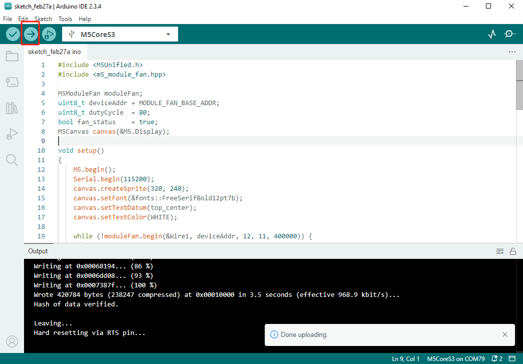
- デバイスポートを選択し、Arduino IDE 左上のコンパイル/アップロードボタンをクリックします。プログラムのコンパイルが完了し、デバイスにアップロードされるまで待機します。
5. 拡張効果
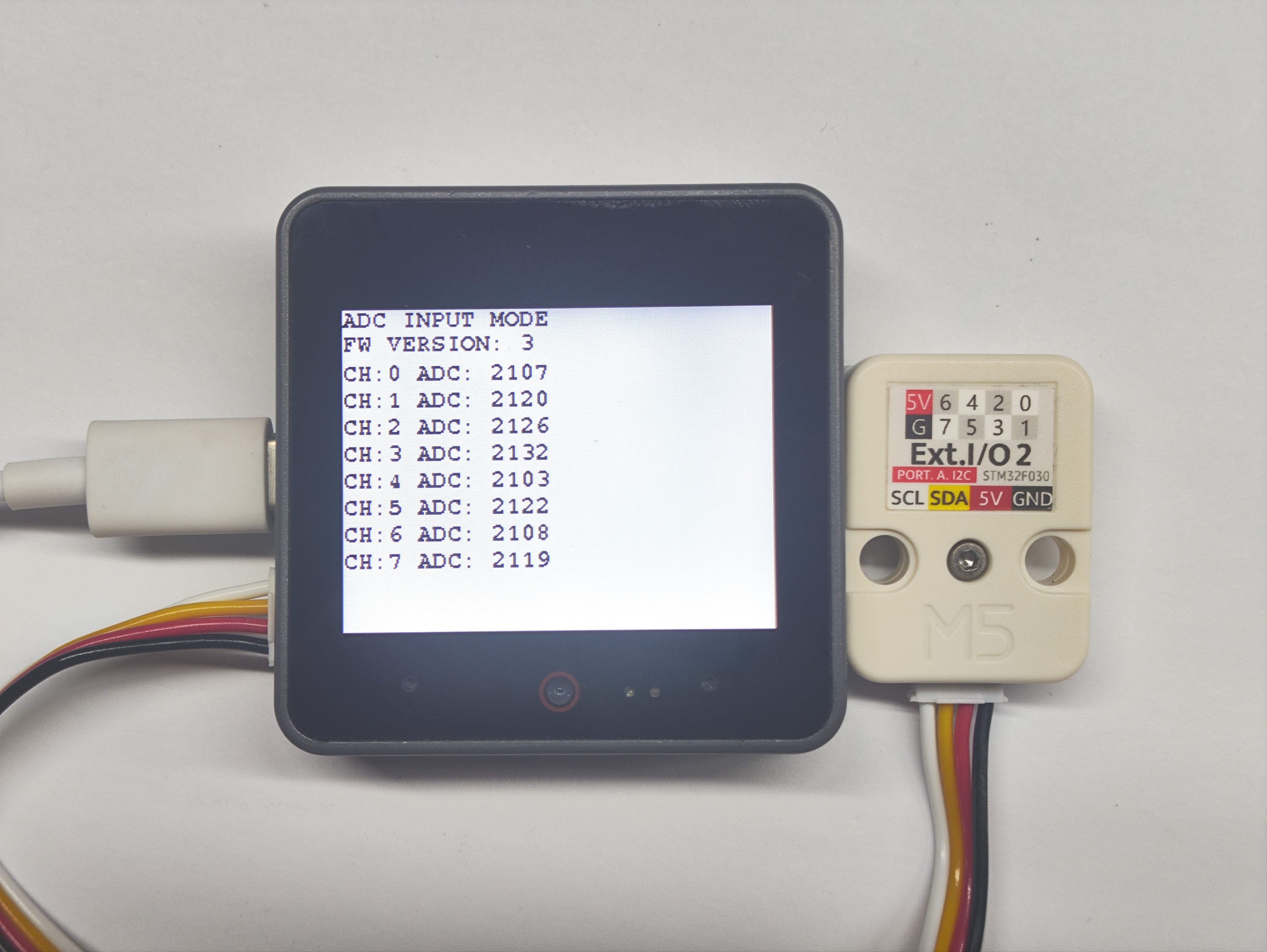
- ADC_INPUT モードでは、各チャンネルのアナログ値を読み取ることができます。
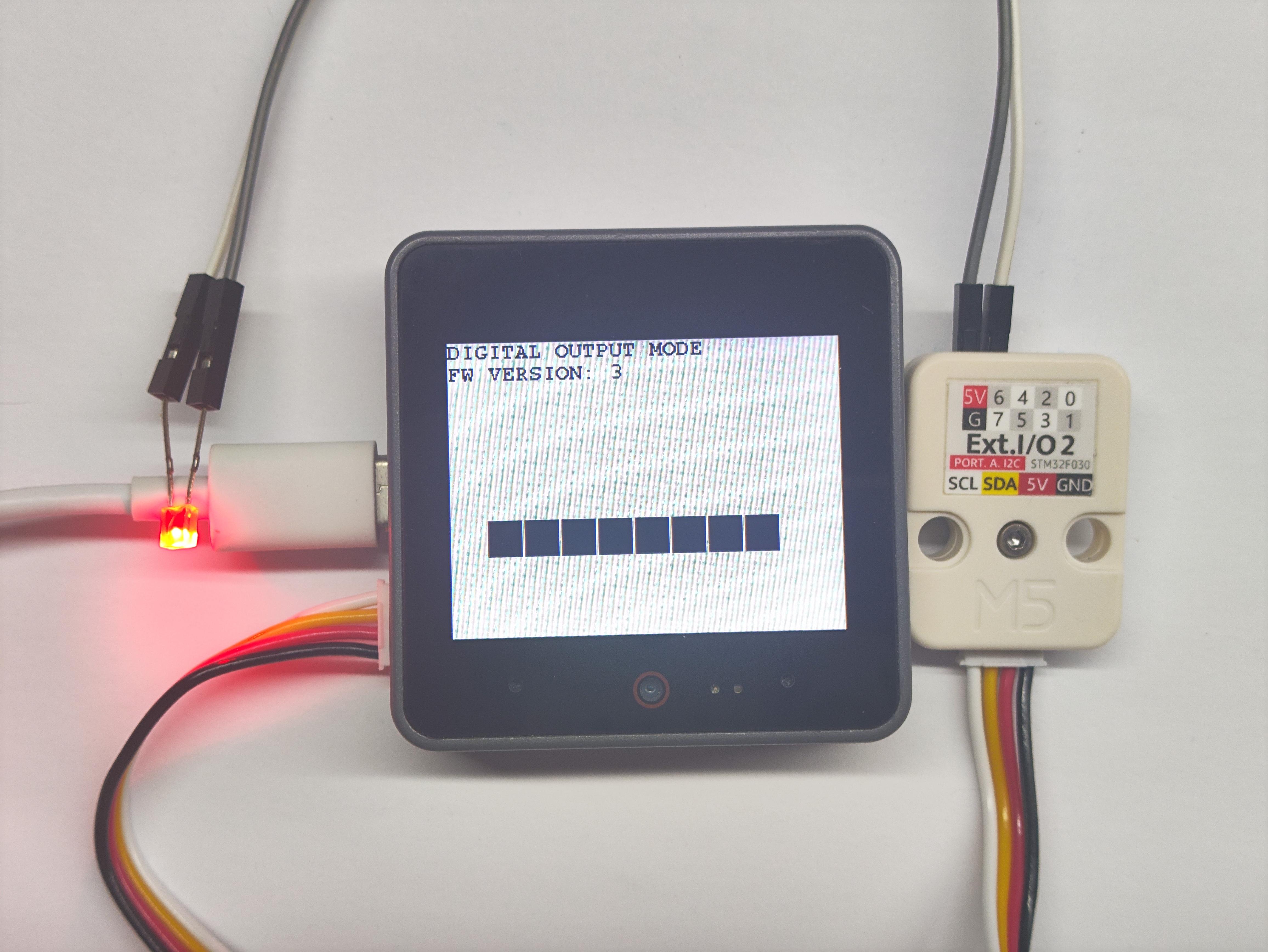
- デジタル出力モードでは、LED を接続してピンのレベル変化を可視化できます。
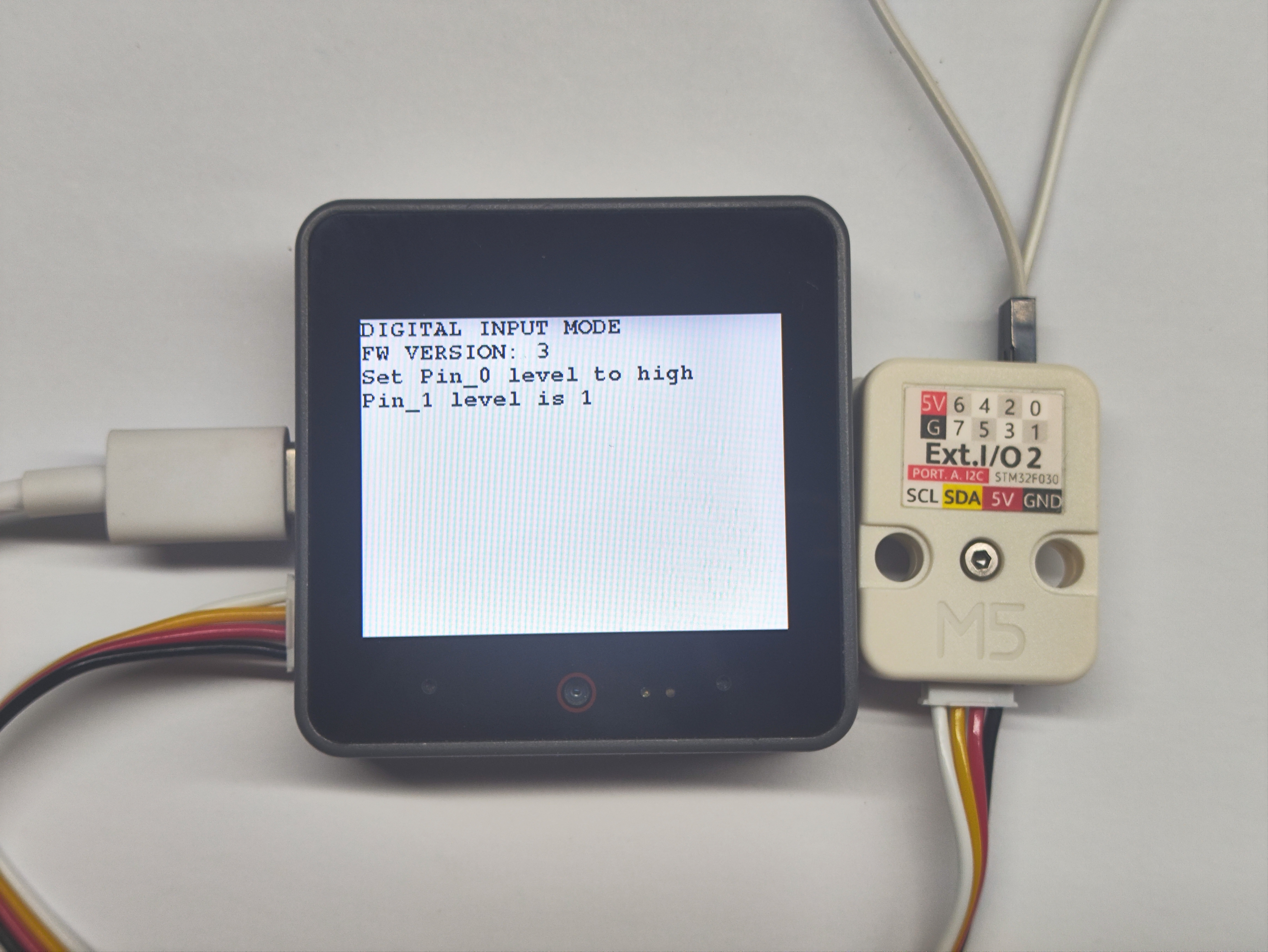
- デジタル入力モードでは、1つのピンでハイレベルを出力し、別のピンで読み取ることでレベル状態を判断できます。
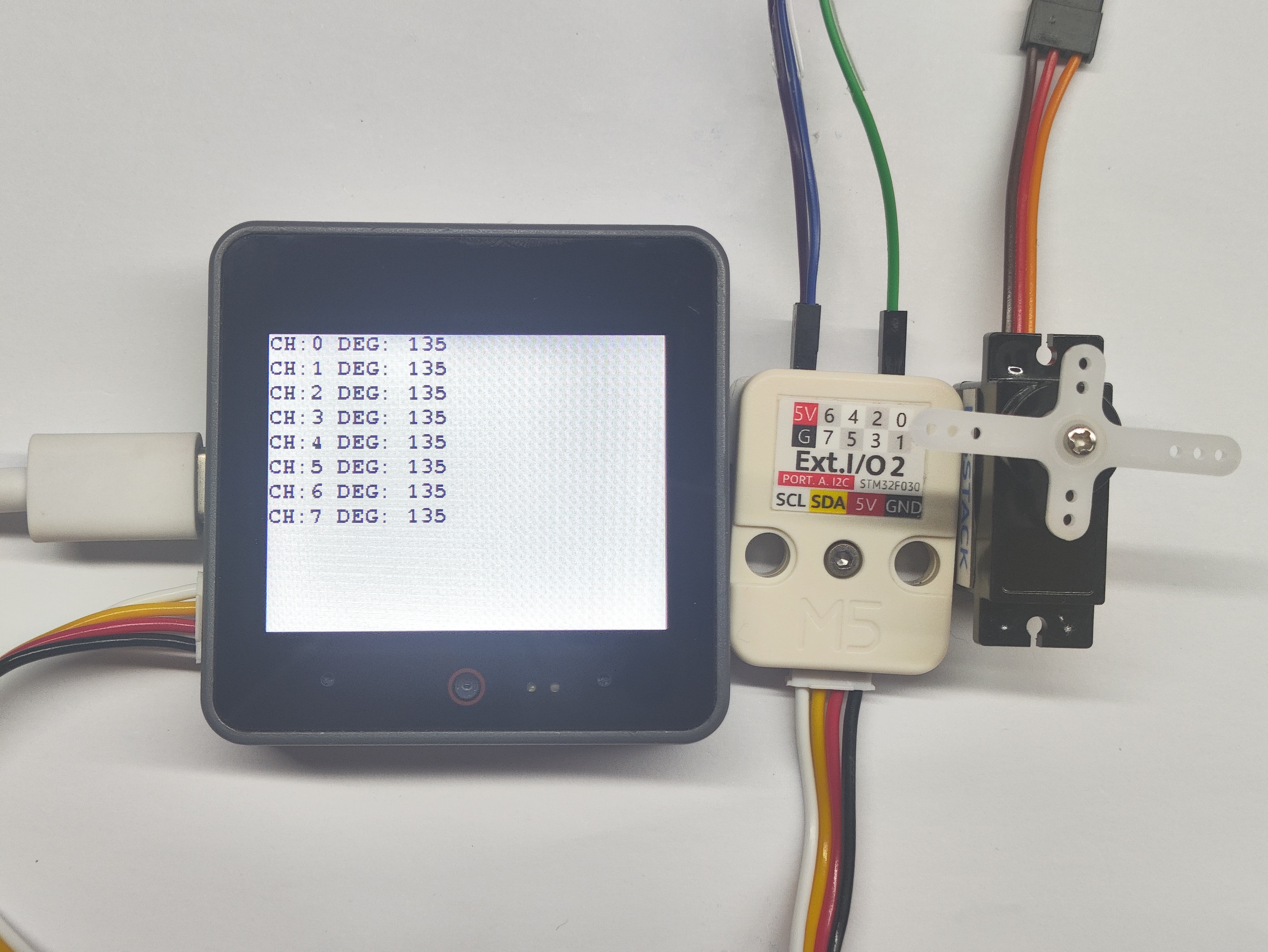
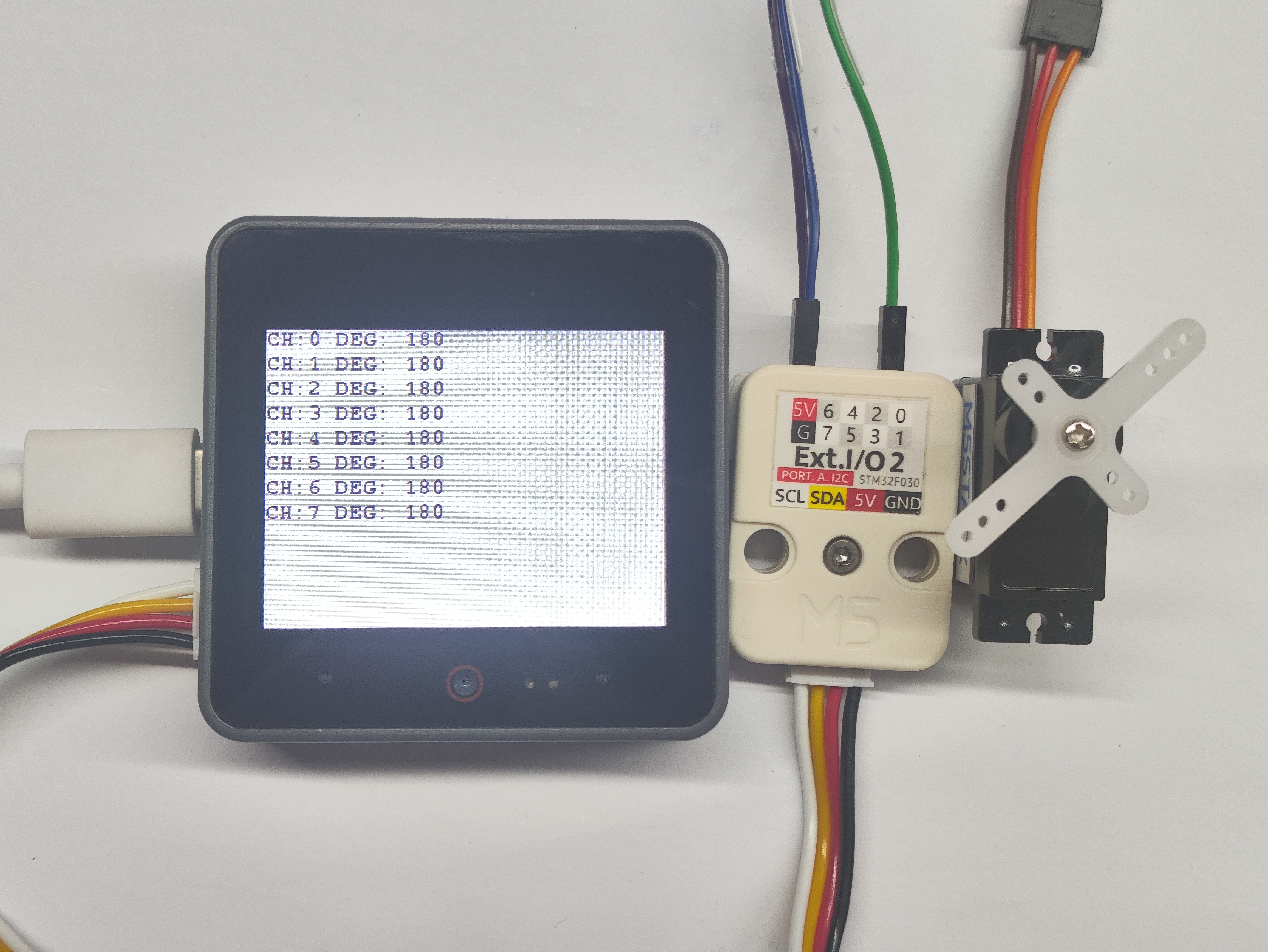
- SERVO モードでは、ピンがPWM信号を出力してサーボを駆動できます。
