Unit Step16 Arduino 使用チュートリアル
1. 準備作業
- 環境設定: Arduino IDE 入門チュートリアルを参考に IDE のインストールを完了し、使用する開発ボードに応じたボード管理と必要なライブラリをインストールしてください。
- 使用するライブラリ:
注意
GitHub から最新のライブラリバージョンをダウンロードする必要があります: M5Unit-Step16 - M5Stack GitHub。Arduino ライブラリマネージャーからダウンロードしないでください(参考チュートリアル: こちら)
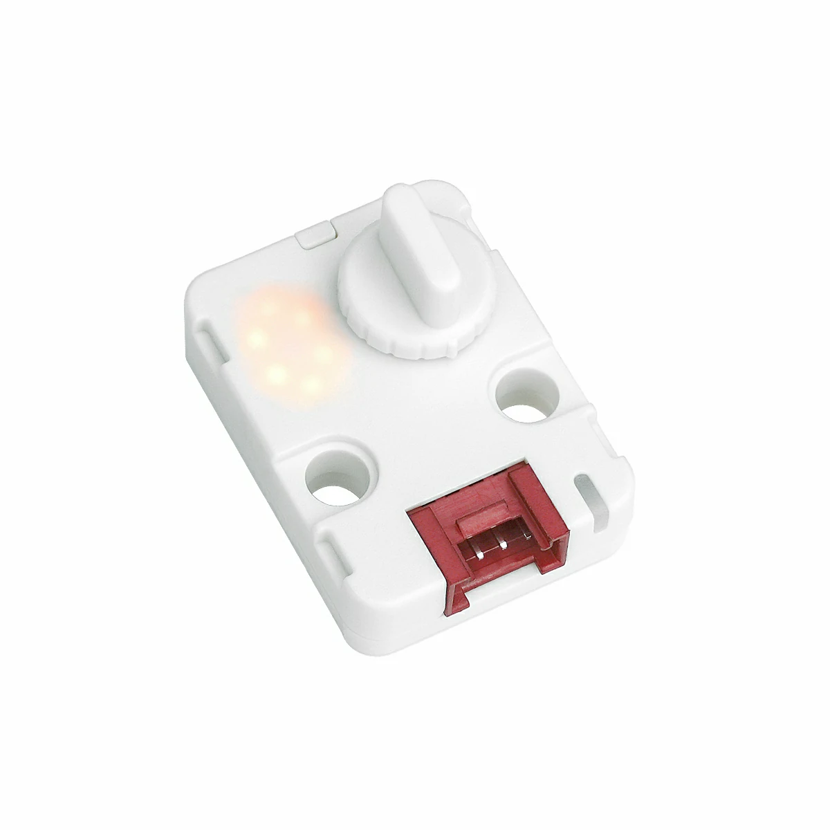
- 使用するハードウェア製品:
2. 注意事項
ピン互換性
各ホストデバイスのピン構成が異なるため、M5Stack 公式がピン互換性表を提供しています。実際のピン接続に応じてサンプルプログラムを修正してください。
3. サンプルプログラム
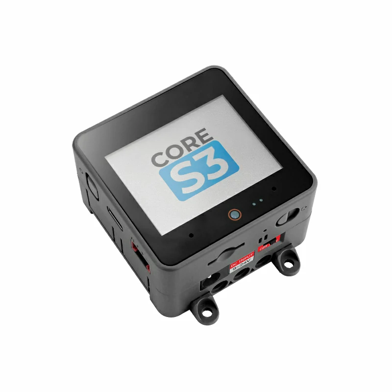
- 本チュートリアルで使用するメインコントローラは CoreS3 で、Unit Step16 と組み合わせて使用します。この 16 ステップロータリーエンコーダモジュールは I2C 通信方式を採用しています。実際の回路接続に応じてプログラム内のピン定義を修正してください。デバイス接続時のデフォルト I2C ピンは
G1 (SCL)とG2 (SDA)です。
cpp
1 2 3 4 5 6 7 8 9 10 11 12 13 14 15 16 17 18 19 20 21 22 23 24 25 26 27 28 29 30 31 32 33 34 35 36 37 38 39 40 41 42 43 44 45 46 47 48 49 50 51 52 53 54 55 56 57 58 59 60 61 62 63 64 65 66 67 68 69 70 71 72 73 74 75 76 77 78 79 80 81 82 83 84 85 86 87 88 89 90 91 92 93 94 95 96 97 98 99 100 101 102 103 104 105 106 107 108 109 110 111 112 113 114 115 116 117 118 119 120 121 122 123 124 125 126 127 128 129 130 131 132 133 134 135 136 137 138 139 140 141 142 143 144 145 146
/*
 * SPDX-FileCopyrightText: 2025 M5Stack Technology CO LTD
 *
 * SPDX-License-Identifier: MIT
 */
/*
 * @Hardwares: M5Stack PortA device + Unit Step16
 * @Dependent Library:
 * M5Unit-Step16:https://github.com/m5stack/M5Unit-Step16
 * @description: When the knob is rotated, only 0-8 is displayed,
 *              when raw value reaches 9-F, rotation direction is automatically reversed,
 *              LED brightness follows display value, never zero (minimum 10%),
 *              RGB color follows the 0-8 pattern
 */
#include <M5Unified.h>
#include <M5UnitStep16.h>

#define I2C_SDA_PIN     (2)
#define I2C_SCL_PIN     (1)
#define NUM_DIGITS      (9)
#define MAX_DIGIT       (8)
#define MIN_DIGIT       (0)
#define MIN_BRIGHTNESS  (10)
#define MAX_BRIGHTNESS  (100)
#define BRIGHTNESS_STEP (10)
#define RGB_BRIGHTNESS  (70)
#define LED_ALWAYS_ON   (0xFF)

UnitStep16 step16;
uint8_t currentDigit = 0;
uint8_t lastRawValue = 0;
bool isFirstRead     = true;

const uint8_t digitBrightness[NUM_DIGITS] = {
    MIN_BRIGHTNESS,                        // 0 - 10%
    MIN_BRIGHTNESS + BRIGHTNESS_STEP,      // 1 - 20%
    MIN_BRIGHTNESS + BRIGHTNESS_STEP * 2,  // 2 - 30%
    MIN_BRIGHTNESS + BRIGHTNESS_STEP * 3,  // 3 - 40%
    MIN_BRIGHTNESS + BRIGHTNESS_STEP * 4,  // 4 - 50%
    MIN_BRIGHTNESS + BRIGHTNESS_STEP * 5,  // 5 - 60%
    MIN_BRIGHTNESS + BRIGHTNESS_STEP * 6,  // 6 - 70%
    MIN_BRIGHTNESS + BRIGHTNESS_STEP * 7,  // 7 - 80%
    MIN_BRIGHTNESS + BRIGHTNESS_STEP * 8   // 8 - 90%
};

struct MyRGBColor {
    uint8_t r, g, b;
    const char* name;
};

const MyRGBColor digitColors[NUM_DIGITS] = {
    {0, 0, 128, "Deep Blue"},       // 0 - cold color
    {0, 64, 192, "Blue"},           // 1
    {0, 128, 255, "Light Blue"},    // 2
    {0, 192, 192, "Cyan"},          // 3
    {0, 255, 128, "Cyan Green"},    // 4
    {128, 255, 0, "Yellow Green"},  // 5
    {192, 192, 0, "Yellow"},        // 6
    {255, 128, 0, "Orange"},        // 7
    {255, 64, 0, "Orange Red"}      // 8 - warm color
};

uint8_t mapRawValueToDigit(uint8_t rawValue);
void updateDisplay(uint8_t digit);
uint8_t mapRawValueToDigit(uint8_t rawValue);
void updateDisplay(uint8_t digit);
void handleValueChange(uint8_t oldVal, uint8_t newVal);

void setup()
{
    M5.begin();
    Serial.begin(115200);
    Wire.begin(I2C_SDA_PIN, I2C_SCL_PIN);
    while(!step16.begin()){
        delay(1000);
        Serial.println("M5Unit-Step16 not found!");
    }
    M5.Display.fillRect(0, 0, 320, 240, WHITE);
    M5.Display.setTextColor(BLACK);
    M5.Display.setFont(&fonts::FreeMonoBold18pt7b);
    M5.Display.setCursor(0, 0);
    M5.Display.printf("M5Unit-Step16\n");
    step16.setRgbConfig(1);
    step16.setRgbBrightness(RGB_BRIGHTNESS);
    lastRawValue = step16.getValue();
    currentDigit = mapRawValueToDigit(lastRawValue);
    updateDisplay(currentDigit);
}

void loop()
{
    uint8_t rawValue = step16.getValue();
    if (rawValue != lastRawValue && !isFirstRead) {
        handleValueChange(lastRawValue, rawValue);
        lastRawValue = rawValue;
        M5.Display.fillRect(0, 0, 320, 240, WHITE);
        M5.Display.setCursor(0, 0);
        M5.Display.printf("Raw Value: %d\n", rawValue);
    }
    if (isFirstRead)    isFirstRead = false;
    delay(50);
}

/**
 * @brief Handle value change
 * @param oldVal Old raw value
 * @param newVal New raw value
 */
void handleValueChange(uint8_t oldVal, uint8_t newVal)
{
    if (newVal >= 9 && newVal <= 15) {
        uint8_t currentDirection = step16.getSwitchState();
        step16.setSwitchState(currentDirection == 0 ? 1 : 0);
    }
    uint8_t newDigit = mapRawValueToDigit(newVal);
    if (newDigit != currentDigit) {
        currentDigit = newDigit;
        updateDisplay(currentDigit);
    }
}

/**
 * @brief Map raw value to digit 0-8
 * @param rawValue Raw value (0-15)
 * @return Mapped digit (0-8)
 */
uint8_t mapRawValueToDigit(uint8_t rawValue)
{
    if (rawValue <= 8) {
        return rawValue;
    } else {
        return 17 - rawValue;
    }
}

/**
 * @brief Update display
 * @param digit Digit to display (0-8)
 */
void updateDisplay(uint8_t digit)
{
    if (digit > MAX_DIGIT) return;
    step16.setLedBrightness(digitBrightness[digit]);
    step16.setRgb(digitColors[digit].r, digitColors[digit].g, digitColors[digit].b);
    step16.setLedConfig(LED_ALWAYS_ON);
}4. コンパイルとアップロード
ダウンロードモード:デバイスにプログラムを書き込む前にダウンロードモードに入る必要があります。この手順はメインコントローラによって異なる場合があります。詳細はArduino IDE入門チュートリアルページ下部のデバイスプログラミングチュートリアルリストを参照してください。
CoreS3 の場合:リセットボタンを約 2 秒間長押しし、内部の緑色 LED が点灯したら離します。これでデバイスはダウンロードモードに入り、プログラミングの準備が整います。
.gif)
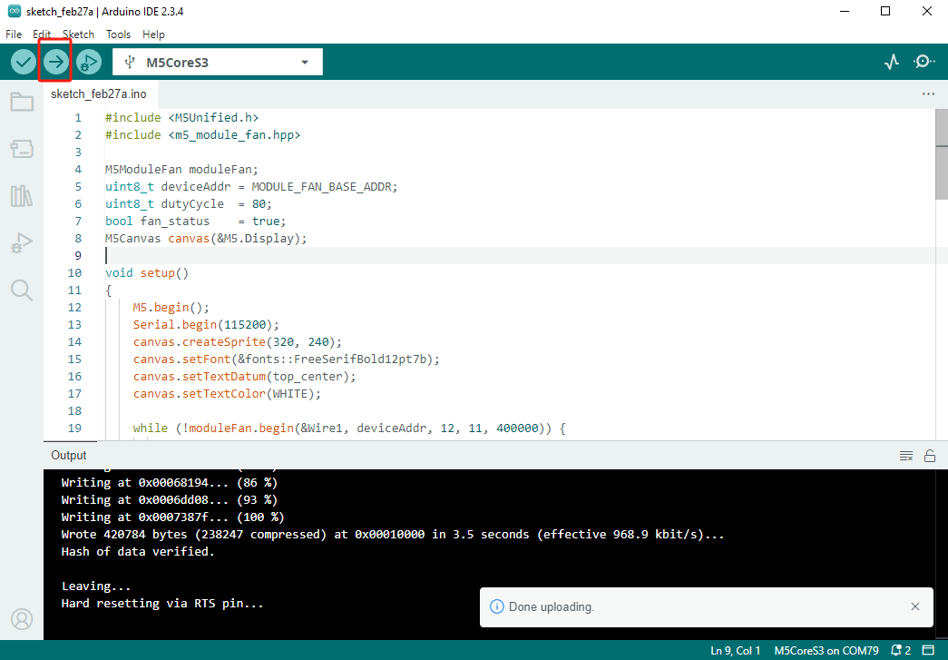
- デバイスポートを選択し、Arduino IDE の左上にあるアップロードボタンをクリックします。プログラムのコンパイルが完了し、デバイスにアップロードされるまで待ちます。
5. 数字表示管の表示
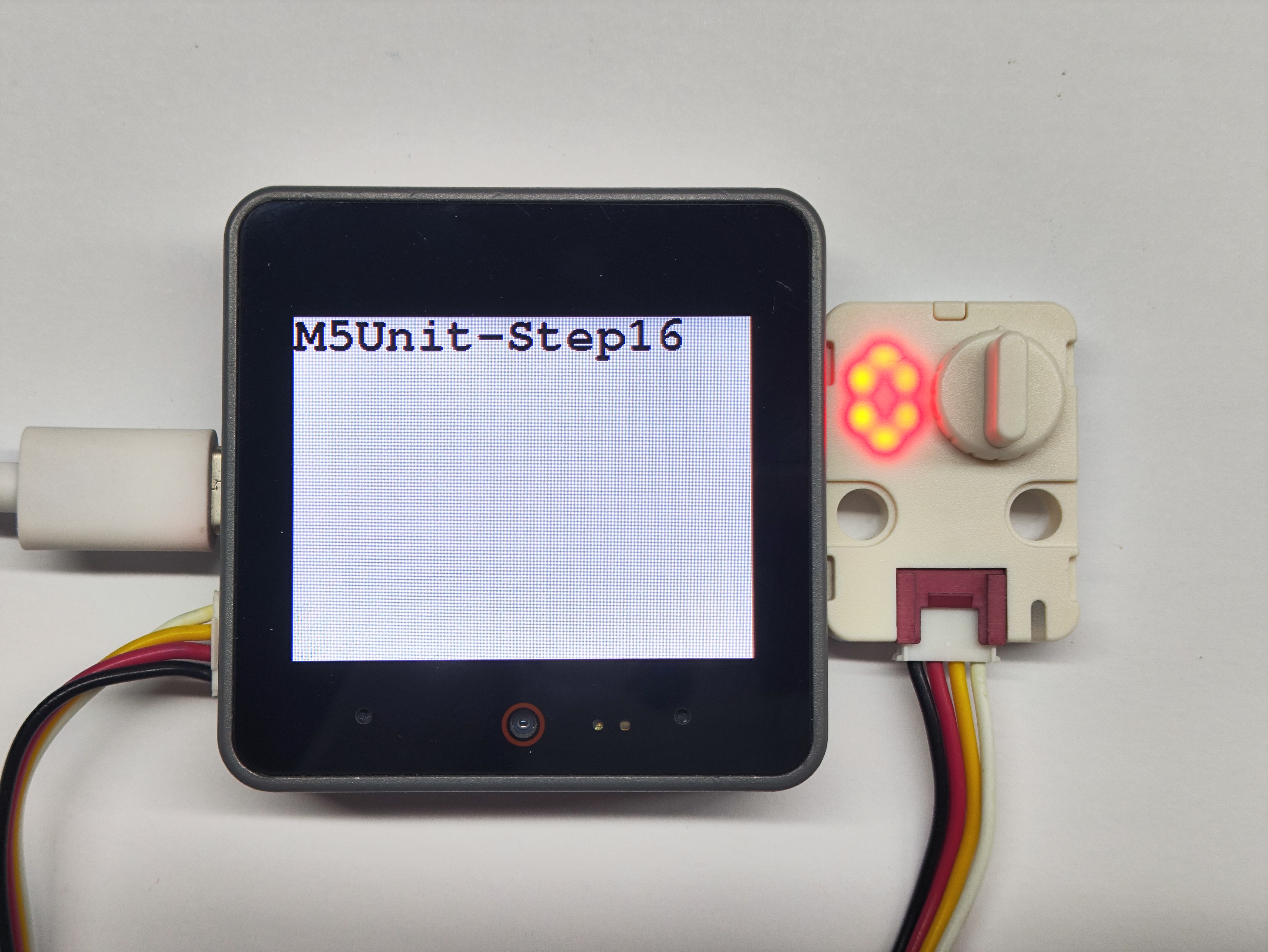
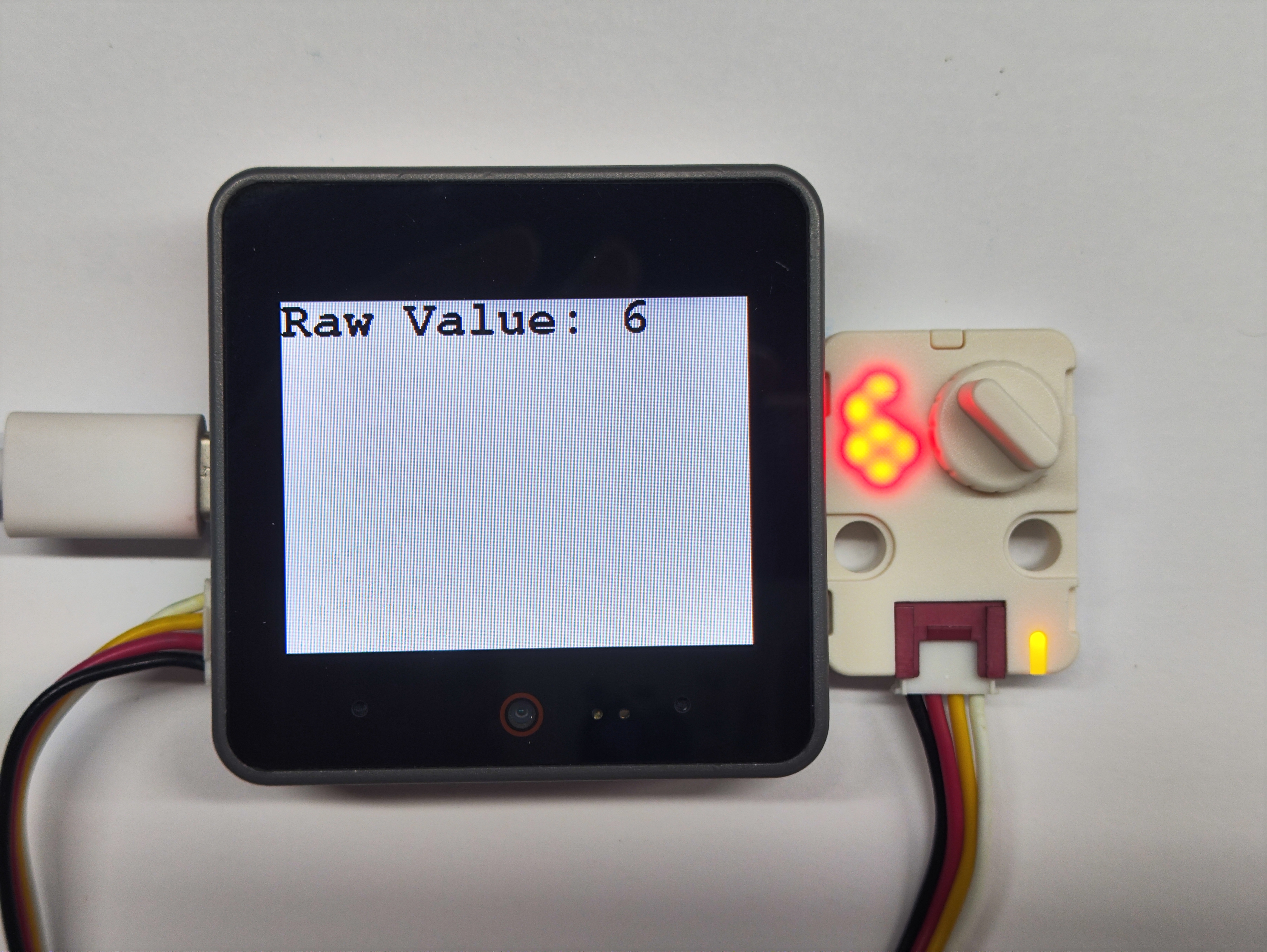
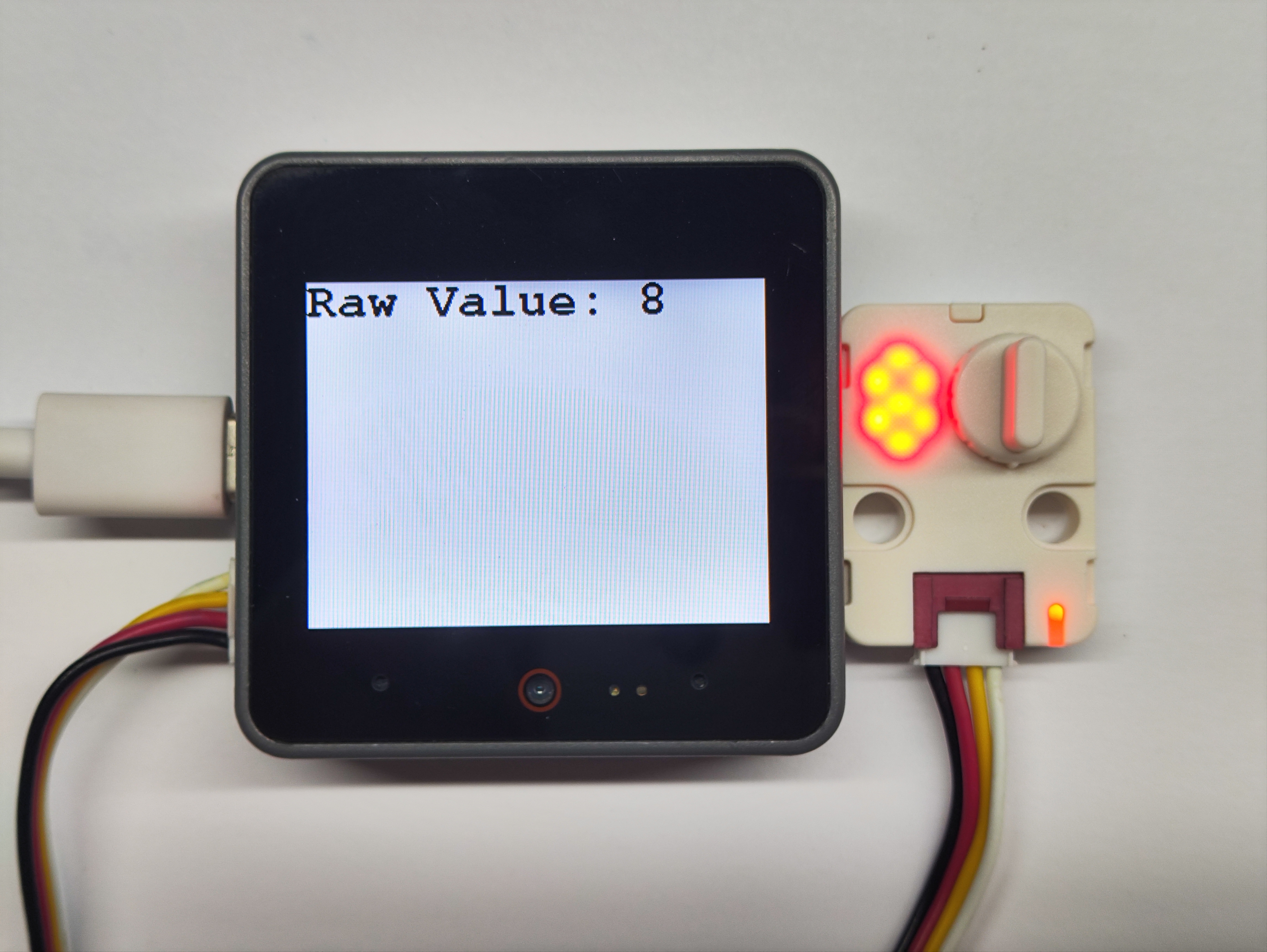
- プログラムの初期状態では数字表示管に 0 が表示されています。ノブを回転させると、表示管の数字が変化し、RGB ライトの色もそれに応じて変化します。
