Unit UWB Arduino チュートリアル
1. 準備作業
環境設定: Arduino IDE 入門ガイドを参照して IDE をインストールし、使用する開発ボードに応じたボード管理と必要なドライバライブラリをインストールしてください。
使用するドライバライブラリ:
使用するハードウェア製品:

2. 注意事項
3. サンプルプログラム
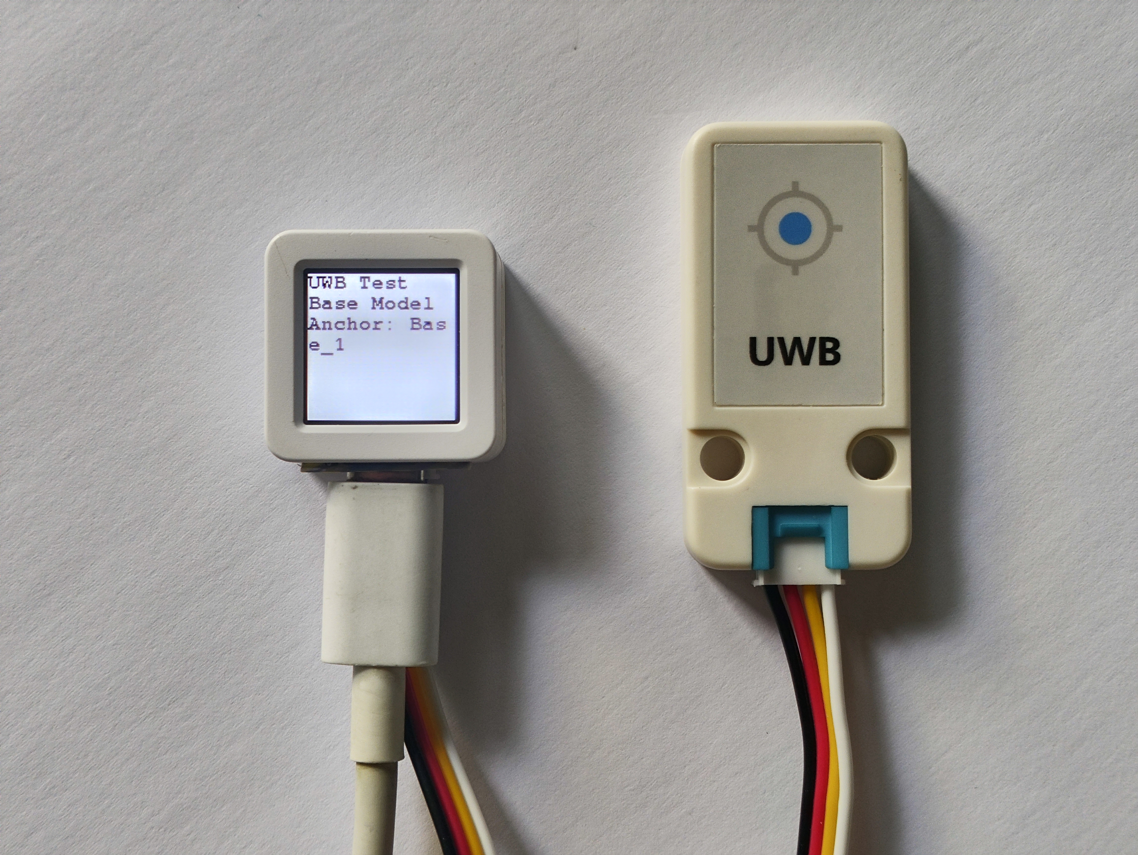
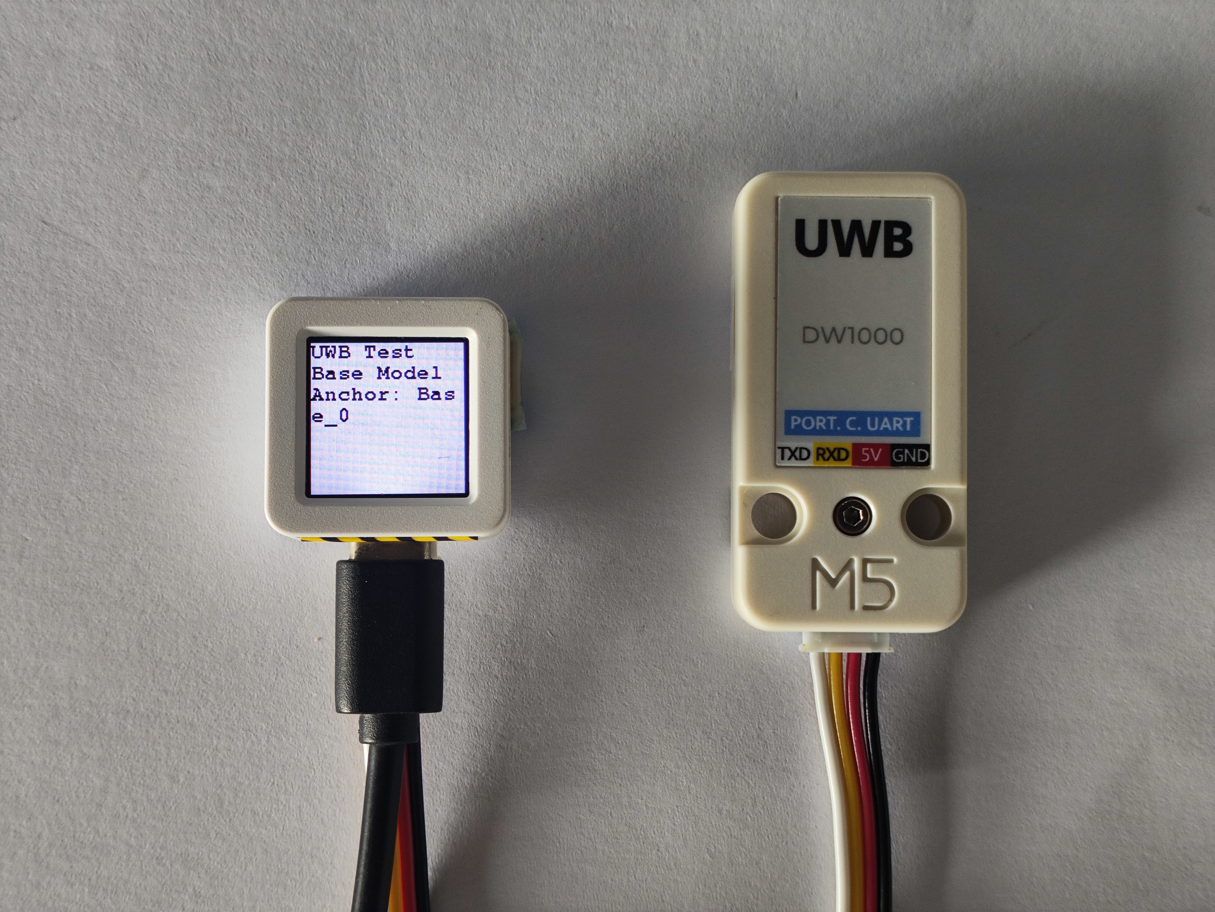
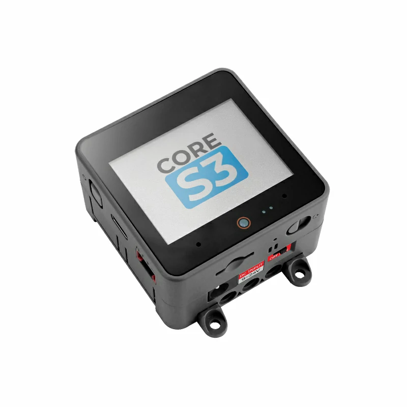
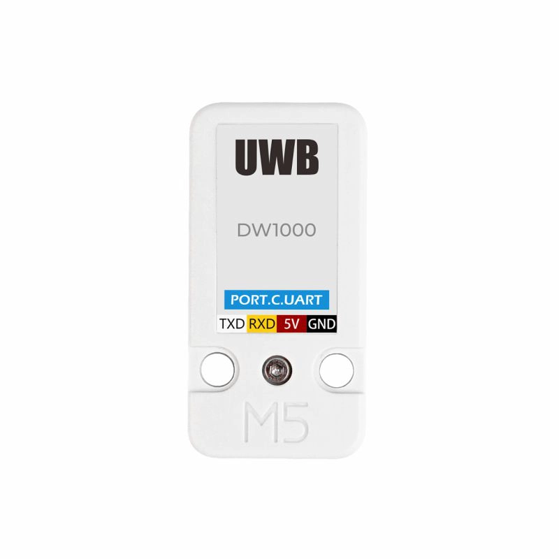
本チュートリアルでは、1 台の CoreS3 と 2 台の AtomS3 をメインコントローラとして使用し、3台のUnit UWBモジュールと組み合わせます。Unit UWBモジュールはUART通信方式を採用しています。実際の回路接続に応じてプログラム内のピン定義を修正し、 CoreS3 と AtomS3 接続後の対応する UART IO はどちらも
G1 (RX)とG2 (TX)です。Unit UWB のサンプルプログラムでは、Anchor の番号設定用に列挙型
UWB_Anchor_numを提供しています。必要に応じて関数setupmode()の値を修正してください(Tag モードでは任意の番号が使用可能です)。Tag 部分のプログラム:
/*
 * SPDX-FileCopyrightText: 2025 M5Stack Technology CO LTD
 *
 * SPDX-License-Identifier: MIT
 *
 *
 * @Hardwares: M5CoreS3 + Unit UWB
 * @Dependent Library:
 * M5Unified: https://github.com/m5stack/M5Unified
 * M5Unit_UWB: https://github.com/m5stack/M5Unit-UWB
 */
#include <M5Unified.h>
#include "M5_UWB.h"

M5_UWB Unit_UWB;
UWB_Mode        Unit_UWB_Mode   = UWB_Mode_Tag;
UWB_Anchor_num  Unit_UWB_Tag    = UWB_Anchor_0; // Select the anchor

bool Uwb_Init = 0;
uint8_t Tag_num       = 0;
uint8_t UI_Init_flag = 0;
void UWB_UI_display();

void setup(){
    M5.begin();
    Serial.begin(115200);
    Unit_UWB.begin(&Serial2, 22, 21, 115200);
    Uwb_Init = Unit_UWB.setupmode(Unit_UWB_Mode, Unit_UWB_Tag, (char *)"5"); // Set the UWB mode and distance value
    if(Uwb_Init){
        Serial.println("UWB Init Success");
    } else {
        Serial.println("UWB Init Failed");
    }
    M5.Display.fillScreen(WHITE);
    M5.Display.setTextColor(BLACK);
    M5.Display.setFont(&fonts::FreeMonoBold9pt7b);
    delay(100);
}

void loop(){
    Tag_num = Unit_UWB.readstring();
    UWB_UI_display();
    delay(100);
}

void UWB_UI_display(){
    if(UI_Init_flag == 0){
      M5.Display.fillScreen(WHITE);
      M5.Display.setCursor(0, 0);
      M5.Display.println("UWB Test");
      M5.Display.println("Tag Model, Distance: \r\n(uint: m)\r\n");
      UI_Init_flag = 1;
    }
    M5.Display.fillRect(0, 60, 340, 240, WHITE);
    M5.Display.setCursor(0, 60);
    M5.Display.print(Unit_UWB.DATA);
    Serial.println(Unit_UWB.DATA);
}- Anchor部分のプログラム:
/*
 * SPDX-FileCopyrightText: 2025 M5Stack Technology CO LTD
 *
 * SPDX-License-Identifier: MIT
 *
 *
 * @Hardwares: AtomS3 + Unit UWB
 * @Platform Version: Arduino M5Stack Board Manager v2.1.3
 * @Dependent Library:
 * M5Unified: https://github.com/m5stack/M5Unified
 * M5Unit_UWB: https://github.com/m5stack/M5Unit-UWB
 */
#include <M5Unified.h>
#include "M5_UWB.h"

M5_UWB Unit_UWB;
UWB_Mode Unit_UWB_Mode = UWB_Mode_Base;
UWB_Anchor_num Unit_UWB_Anchor = UWB_Anchor_1; // Select the anchor point

bool Uwb_Init = 0;
uint8_t Tag_num       = 0;
uint8_t UI_Init_flag = 0;
void UWB_UI_display();

const char* getAnchornNum(UWB_Anchor_num Num) {
    switch (Num) {
        case UWB_Anchor_0:      return "Base_0";
        case UWB_Anchor_1:      return "Base_1";
        case UWB_Anchor_2:      return "Base_2";
        case UWB_Anchor_3:      return "Base_3";
        case UWB_Anchor_4:      return "Base_4";
        default:                return "Unknown";
    }
}

void setup(){
    M5.begin();
    Serial.begin(115200);
    Unit_UWB.begin(&Serial2, 1, 2, 115200);
    Uwb_Init = Unit_UWB.setupmode(Unit_UWB_Mode, Unit_UWB_Anchor, (char *)"5"); // Set the UWB mode and distance value
    if(Uwb_Init){
        Serial.println("UWB Init Success");
    } else {
        Serial.println("UWB Init Failed");
    }
    M5.Display.fillScreen(WHITE);
    M5.Display.setTextColor(BLACK);
    M5.Display.setFont(&fonts::FreeMonoBold9pt7b);
    delay(100);
}

void loop(){
    Tag_num = Unit_UWB.readstring();
    UWB_UI_display();
    delay(100);
}

void UWB_UI_display(){
    if(UI_Init_flag == 0){
      M5.Display.fillScreen(WHITE);
      M5.Display.setCursor(0, 0);
      M5.Display.println("UWB Test");
      M5.Display.println("Base Model");
      const char * current_num = getAnchornNum(Unit_UWB_Anchor);
      M5.Display.printf("Anchor: %s", current_num);
      UI_Init_flag = 1;
    }
    M5.Display.setCursor(0, 80);
    M5.Display.print(Unit_UWB.DATA);
    Serial.println(Unit_UWB.DATA);
}3. コンパイルと書き込み
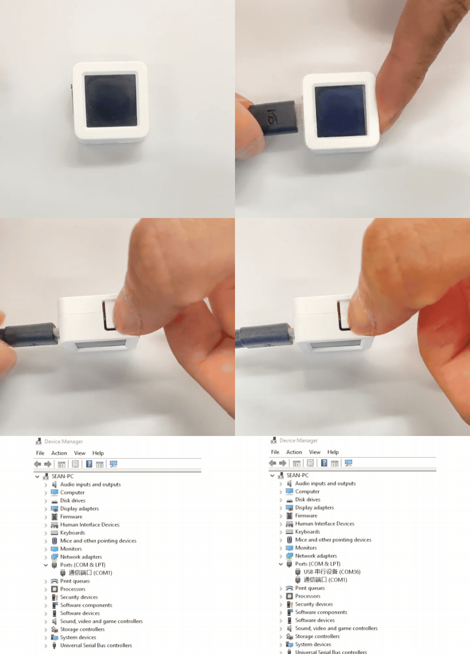
ダウンロードモード:デバイスごとにプログラム書き込み前にダウンロードモードに入る必要があります。この手順はメインコントローラによって異なる場合があります。詳細はArduino IDE入門ガイドのページ下部にあるデバイス別プログラム書き込みチュートリアルリストを参照してください。
CoreS3 と AtomS3 の書き込み方法は同じ:リセットボタンを長押し(約 2 秒)し、内部の緑色 LED が点灯するまで待ってから離します。これでデバイスはダウンロードモードに入り、書き込み待機状態になります。
.gif)
- デバイスポートを選択し、Arduino IDE の左上にある書き込みボタンをクリックします。プログラムがコンパイルされ、デバイスに書き込まれるのを待ちます。

4. 屋内測距
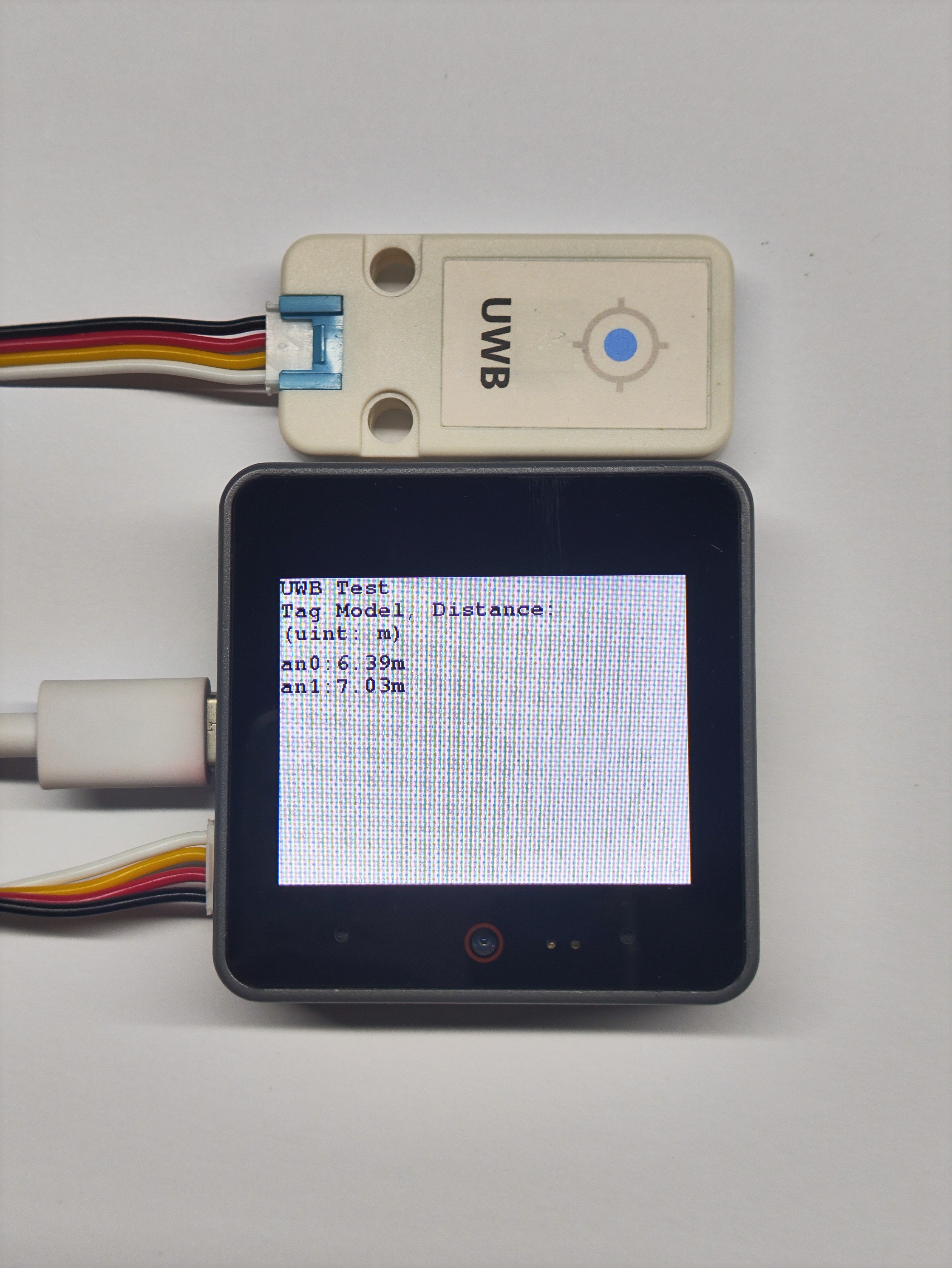
ここでは 2 台の AtomS3 にUnit UWB モジュールを接続して Anchor として、1 台の CoreS3 に Unit UWB モジュールを接続して Tag として使用します(Anchor と Tag の距離は 5-50m 程度が最適です)。
Tag の動作例:
- Anchor の動作例:
