


Arduino Quick Start
2. Devices & Examples
3. M5Unified
4. M5GFX
5. Extensions
Unit
Base
IoT
Accessories
Unit MIC Arduino Tutorial
1. Preparation
Environment configuration: Refer to Arduino IDE Quick Start to complete the IDE installation, install the corresponding board management according to the development board in use, and install the required driver libraries.
Driver libraries used:
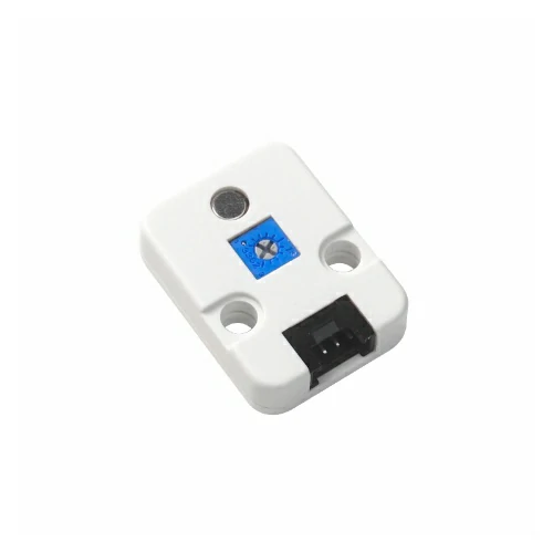
Hardware products used:
2. Notes
Pin Compatibility
Due to different pin configurations for each host device, to make it easier for users to use, M5Stack officially provides a pin compatibility chart for easy reference. Please modify the example program according to the actual pin connection situation.
3. Example Program
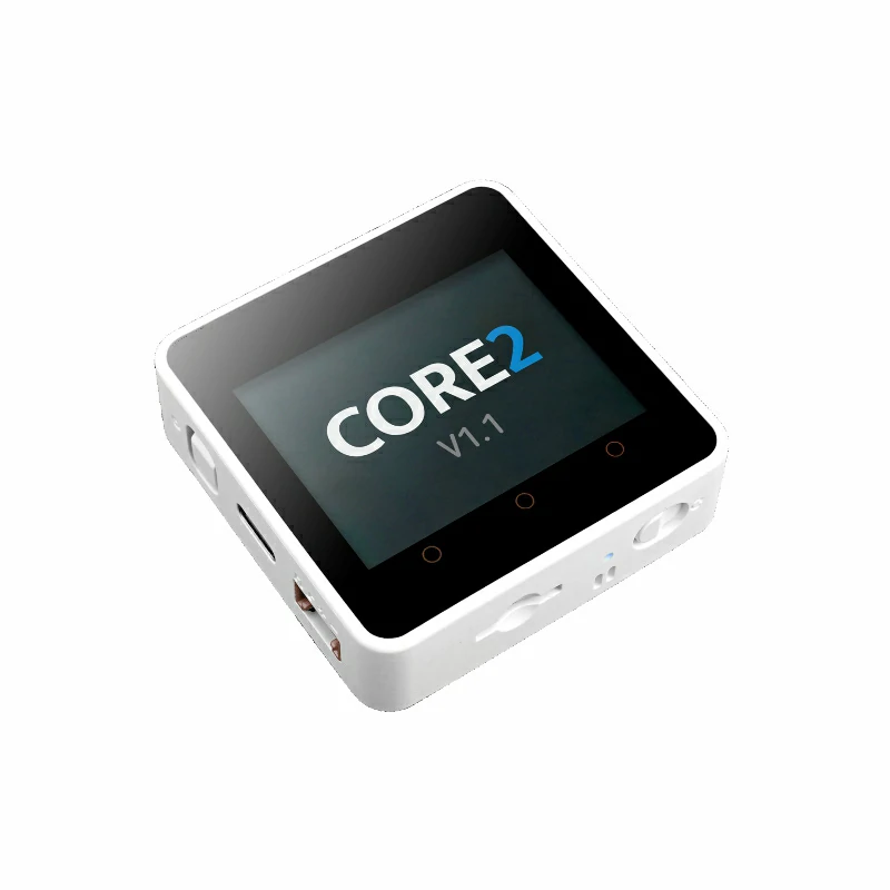
In this tutorial, the main control device used is Core2 v1.1, paired with Unit MIC. Please modify the pin definitions in the program according to your actual circuit connections. After the device is connected, the corresponding pins are G33 (AIN) and G32 (DIN).
cpp
1 2 3 4 5 6 7 8 9 10 11 12 13 14 15 16 17 18 19 20 21 22 23 24 25 26 27 28 29 30 31 32 33 34 35 36 37 38 39 40 41 42 43 44 45 46 47 48 49 50 51 52 53 54 55 56 57 58 59 60 61 62 63 64 65 66 67 68 69 70 71 72 73 74 75 76 77 78 79 80 81 82 83 84 85 86 87 88 89 90 91 92 93 94 95 96 97 98 99 100 101
#include <M5Unified.h>
#include <M5GFX.h>

// Input pins
#define AIN_PIN 33      // Analog input pin
#define DIN_PIN 32      // Digital input pin (ADC)
#define LCD_W 320
#define LCD_H 240
#define MAX_LEN LCD_W   // Buffer length (matches screen width)
#define X_OFFSET 0

#define Y_AIN_OFFSET 60   // Vertical offset for AIN waveform
#define Y_DIN_OFFSET 150  // Vertical offset for DIN waveform
#define X_SCALE 1         // Amplitude scaling factor

// Draw real-time waveforms and values for AIN and DIN channels
static void draw_waveform_dual() {
  static int16_t ain_buf[MAX_LEN] = {0};  // Buffer for AIN samples
  static int16_t din_buf[MAX_LEN] = {0};  // Buffer for DIN samples
  static int16_t pt = MAX_LEN - 1;        // Circular buffer pointer

  int ainValue = analogRead(AIN_PIN);     // Read AIN ADC value
  int dinValue = analogRead(DIN_PIN);     // Read DIN ADC value

  // Map AIN: higher ADC values produce higher positions
  ain_buf[pt] = map((int16_t)(ainValue * X_SCALE), 1800, 4095, 0, 80);

  // Map DIN: ADC=0 at waveform bottom, ADC=4095 at waveform top
  din_buf[pt] = map((int16_t)(dinValue * X_SCALE), 0, 4095, 80, 0);

  if (--pt < 0) pt = MAX_LEN - 1;         // Circular buffer wrap-around

  for (int i = 1; i < MAX_LEN; i++) {
    uint16_t now_pt = (pt + i) % MAX_LEN;

    // Erase previous AIN waveform points
    M5.Lcd.drawLine(
      i + X_OFFSET,
      ain_buf[(now_pt + 1) % MAX_LEN] + Y_AIN_OFFSET,
      i + 1 + X_OFFSET,
      ain_buf[(now_pt + 2) % MAX_LEN] + Y_AIN_OFFSET,
      TFT_BLACK);

    // Erase previous DIN waveform points
    M5.Lcd.drawLine(
      i + X_OFFSET,
      din_buf[(now_pt + 1) % MAX_LEN] + Y_DIN_OFFSET,
      i + 1 + X_OFFSET,
      din_buf[(now_pt + 2) % MAX_LEN] + Y_DIN_OFFSET,
      TFT_BLACK);

    if (i < MAX_LEN - 1) {
      // Draw current AIN waveform in green
      M5.Lcd.drawLine(
        i + X_OFFSET,
        ain_buf[now_pt] + Y_AIN_OFFSET,
        i + 1 + X_OFFSET,
        ain_buf[(now_pt + 1) % MAX_LEN] + Y_AIN_OFFSET,
        TFT_GREEN);

      // Draw current DIN waveform in cyan
      M5.Lcd.drawLine(
        i + X_OFFSET,
        din_buf[now_pt] + Y_DIN_OFFSET,
        i + 1 + X_OFFSET,
        din_buf[(now_pt + 1) % MAX_LEN] + Y_DIN_OFFSET,
        TFT_CYAN);
    }
  }

  // Display current AIN ADC value (upper area)
  M5.Lcd.fillRect(10, Y_AIN_OFFSET - 25, 100, 20, TFT_BLACK);
  M5.Lcd.setTextColor(TFT_GREEN, TFT_BLACK);
  M5.Lcd.setTextFont(&fonts::FreeMonoBold9pt7b);
  M5.Lcd.setTextDatum(TL_DATUM);
  M5.Lcd.drawString("AIN: " + String(ainValue), 10, Y_AIN_OFFSET - 24);

  // Display current DIN ADC value (lower area)
  M5.Lcd.fillRect(10, Y_DIN_OFFSET + 80 - 25, 100, 20, TFT_BLACK);
  M5.Lcd.setTextColor(TFT_CYAN, TFT_BLACK);
  M5.Lcd.drawString("DIN: " + String(dinValue), 10, Y_DIN_OFFSET + 80 - 24);
}

void setup() {
  M5.begin();
  M5.Lcd.setTextFont(&fonts::FreeMonoBold9pt7b);
  M5.Lcd.setTextDatum(top_center);

  // AIN waveform label
  M5.Lcd.setTextColor(TFT_GREEN, TFT_BLACK);
  M5.Lcd.setTextDatum(top_center);
  M5.Lcd.drawString("AIN Wave", 220, Y_AIN_OFFSET - 24);

  // DIN waveform label (near bottom)
  M5.Lcd.setTextColor(TFT_CYAN, TFT_BLACK);
  M5.Lcd.drawString("DIN Wave", 220, Y_DIN_OFFSET + 80 - 24);
}

void loop() {
  draw_waveform_dual();
}4. Compile and Upload
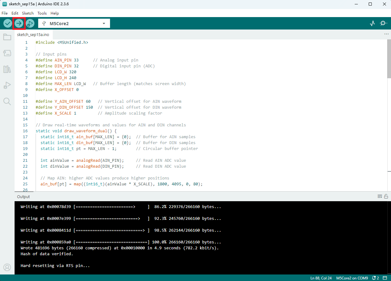
- Select the device port (for details, please refer to Program Compilation and Upload), click the compile and upload button in the upper left corner of the Arduino IDE, and wait for the program to complete compilation and upload to the device.
5. Microphone Function Demonstration
- This example draws the audio waveform and collected ADC values in real time. The display on the main control device is shown in the figure below. \
