


Arduino Quick Start
2. Devices & Examples
3. M5Unified
4. M5GFX
5. Extensions
Unit
Base
IoT
Accessories
Atomic CAN Base Arduino Tutorial
1. Preparation
Environment setup: Refer to Arduino IDE Quick Start to complete IDE installation, and install the corresponding board package for the development board in use along with the required driver libraries.
Required libraries:
Required hardware products:
2. CAN Communication Overview
CAN (Controller Area Network) is a multi-master, high-reliability serial communication protocol widely used in automotive electronics, industrial automation, and other applications that demand high real-time performance and reliability. A CAN network supports equal access for multiple nodes and features excellent error detection and arbitration mechanisms.
1. Core Definition:
- Controller Area Network (CAN) is a multi-master, non-hierarchical serial communication protocol that defines standards for the physical and data link layers.
- Supports multi-master communication, where all nodes are equal and can actively initiate data transmission without a central arbiter.
2. Key Features:
- Communication distance: At 1Mbps, maximum distance is 40 meters; reducing speed (e.g., to 10Kbps) extends range to up to 10 kilometers.
- Transmission rate: Standard CAN supports from 10Kbps to 1Mbps, with rate inversely proportional to distance.
- Node capacity: Theoretically up to 110 nodes per bus; in practice, dozens of nodes are common.
- Anti-interference: Uses differential transmission (two signal lines CAN_H/CAN_L) with strong resistance to electromagnetic interference and high reliability.
3. Working Principle:
- Voltage levels: Dominant level (logic "0") CAN_H ≈ 3.5V, CAN_L ≈ 1.5V; Recessive level (logic "1") both lines ≈ 2.5V.
- Transmitter: Encodes data as differential signals and transmits via CAN_H and CAN_L.
- Receiver: Detects the voltage difference between CAN_H and CAN_L to restore data; all nodes can receive bus data.
- Interface form: Two-wire (CAN_H, CAN_L), with typical terminal wiring or DB9 (9-pin) connectors.
A 120Ω termination resistor must be connected in parallel at both ends of the busto ensure signal integrity.
3. Example Program
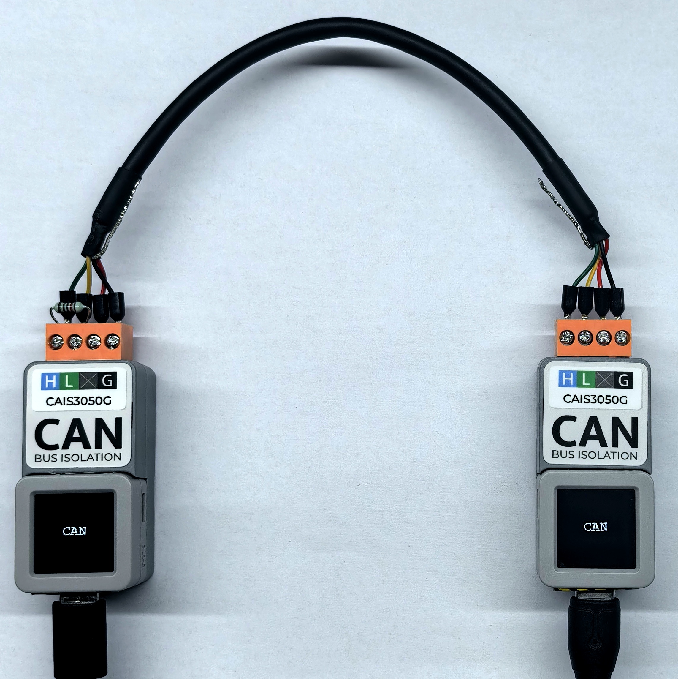
- This tutorial uses AtomS3R as the main controller paired with Atomic CAN Base. The module communicates via UART. Modify the pin definitions in the program based on actual wiring; after connection, the corresponding UART pins are
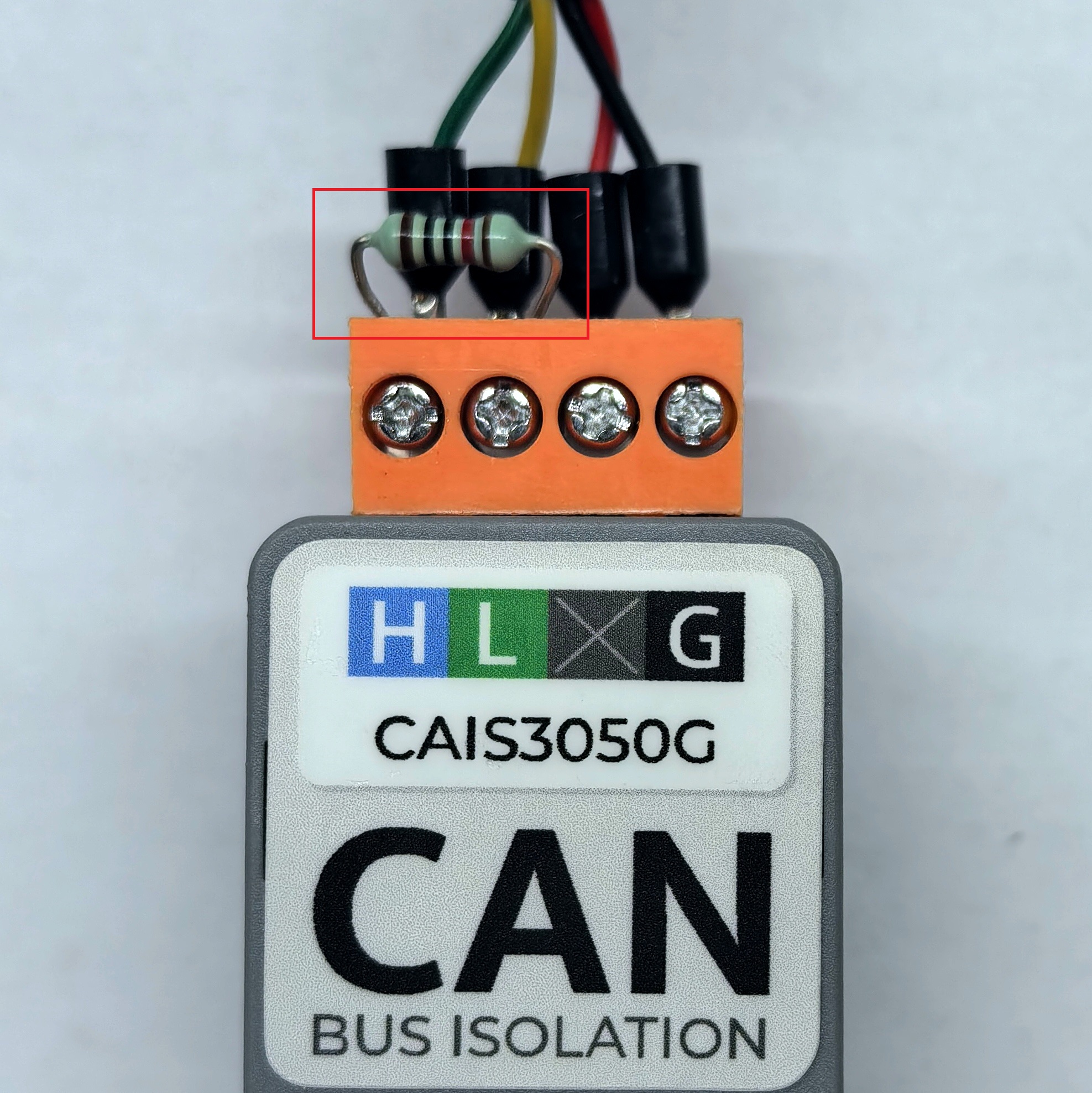
G5 (RX)andG6 (TX). - This module does not have a built-in 120Ω termination resistor; you can connect 120Ω resistors in parallel at both ends of the CAN bus as shown in the figure below.
cpp
1 2 3 4 5 6 7 8 9 10 11 12 13 14 15 16 17 18 19 20 21 22 23 24 25 26 27 28 29 30 31 32 33 34 35 36 37 38 39 40 41 42 43 44 45 46 47 48 49 50 51 52 53
#include <M5Unified.h>
#include <M5GFX.h>
#include "driver/twai.h"

const gpio_num_t MCU_CAN_TXD = GPIO_NUM_5;
const gpio_num_t MCU_CAN_RXD = GPIO_NUM_6;

void setup() {
  M5.begin();
  M5.Display.clear();
  M5.Display.setFont(&fonts::FreeMonoBold12pt7b);
  Serial.begin(115200);

  twai_general_config_t g_config = TWAI_GENERAL_CONFIG_DEFAULT(MCU_CAN_TXD, MCU_CAN_RXD, TWAI_MODE_NORMAL);
  twai_timing_config_t t_config = TWAI_TIMING_CONFIG_500KBITS();
  twai_filter_config_t f_config = TWAI_FILTER_CONFIG_ACCEPT_ALL();

  if (twai_driver_install(&g_config, &t_config, &f_config) == ESP_OK && twai_start() == ESP_OK) {
    Serial.println("\nCAN ready. ");
  } else {
    Serial.println("\nCAN init failed. ");
    while (1) delay(1000);
  }

  M5.Display.drawCenterString("CAN", 64, 50);
}

void loop() {
  // transmit
  twai_message_t tx_msg = {};
  tx_msg.extd = 0;            // 0 = standard frame, 1 = extended frame
  tx_msg.identifier = 0x123;  // 11-bit standard ID, change it on another device
  tx_msg.data_length_code = 2;
  tx_msg.data[0] = 0xAA;  // change it on another device
  tx_msg.data[1] = 0xBB;  // change it on another device

  if (twai_transmit(&tx_msg, pdMS_TO_TICKS(100)) == ESP_OK) {
    Serial.println("TX OK");
  } else {
    Serial.println("TX failed");
  }

  // receive (non-blocking)
  twai_message_t rx_msg;
  if (twai_receive(&rx_msg, pdMS_TO_TICKS(10)) == ESP_OK) {
    Serial.print("RX: ");
    for (int i = 0; i < rx_msg.data_length_code; i++) Serial.printf("%02X ", rx_msg.data[i]);
    Serial.printf("(ext=%d, id=0x%X, dlc=%d)", rx_msg.extd, rx_msg.identifier, rx_msg.data_length_code);
    Serial.println();
  }

  delay(2000);
} 4. Compile and Upload
- 1. Download mode: Devices must enter download mode before flashing the program; steps vary depending on the main controller. For details, refer to the device program download tutorial list at the bottom of the Arduino IDE Quick Start page.
- For AtomS3R, press and hold the reset button (about 2 seconds) until the internal green LED lights up, then release. The device is now in download mode, waiting for flashing.
- 2. Select the device port, click the compile/upload button in the upper left of Arduino IDE, and wait for compilation and upload to the device.
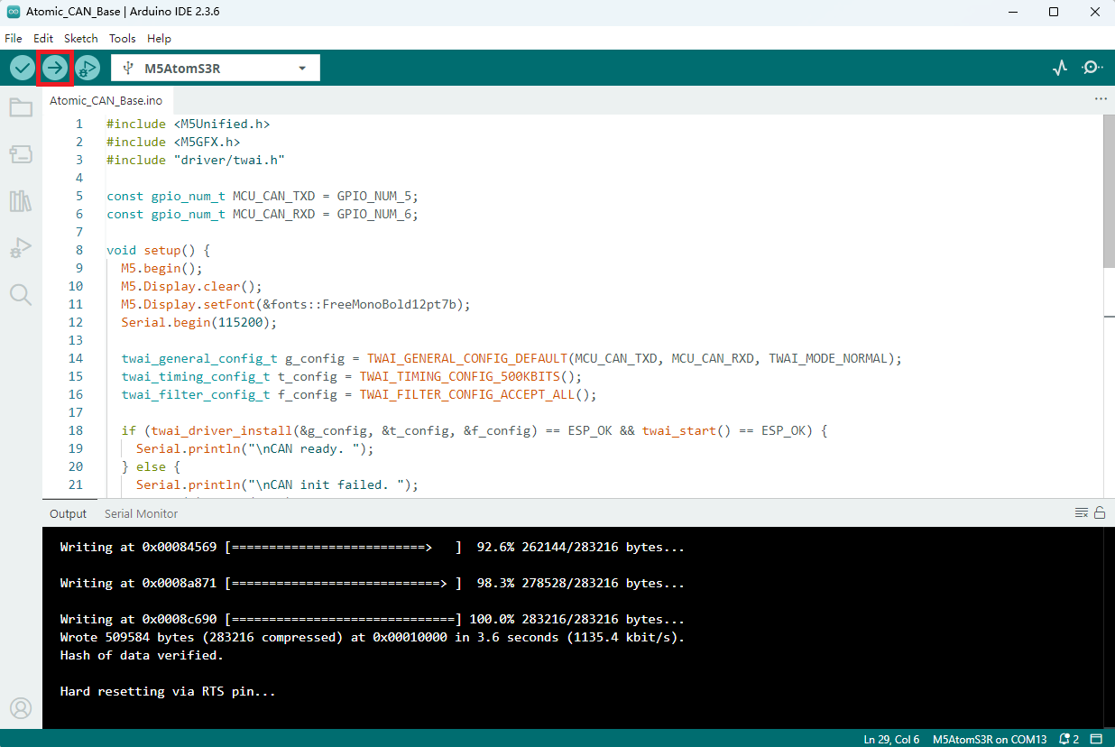
5. Example Output Display
- After powering on, the serial monitor will display the CAN bus transmit and receive information. The wiring is shown below.
- Serial output:
Transmitter:TX OK
Receiver:RX: AA BB (ext=0, id=0x123, dlc=2)