

Arduino Quick Start
2. Devices & Examples
3. M5Unified
4. M5GFX
5. Extensions
Unit
Atomic
Tab5
IoT
Accessories
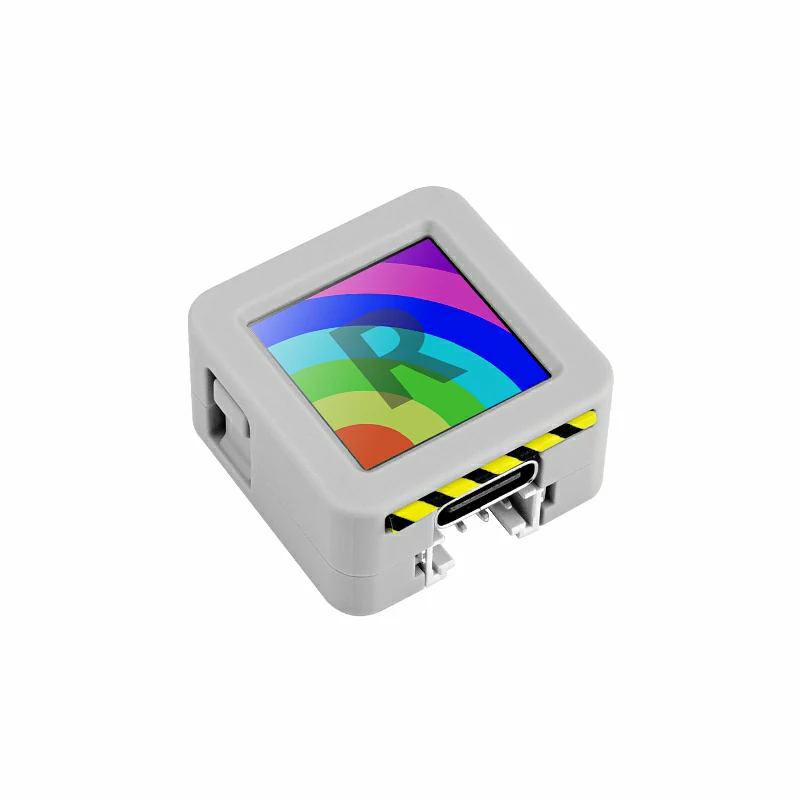
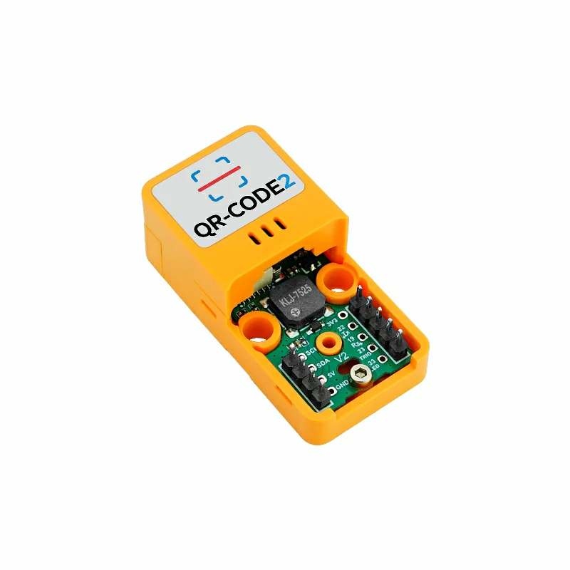
Atomic QRCode2 Base Arduino Tutorial
1. Preparation
Environment setup: Refer to the Arduino IDE Getting Started Guide to install the IDE, and install the appropriate board package and required libraries for your development board.
Required libraries:
Required hardware:
2. Example
- The main controller used in this tutorial is AtomS3R, paired with Atomic QRCode2 Base. This scanner module communicates via UART. Modify the pin definitions in the sample according to your wiring. After connection the UART IO pins are
G5 (TX)andG6 (RX).
Note
1. This module uses the same driver library family as similar products, but it can only be controlled via UART — do NOT use I2C-related features from the M5UnitQRCode library.
2. The example below defaults to manual scan mode; the user can press the host device screen to trigger a single scan/decode. To enable automatic scan mode, uncomment the
3.
2. The example below defaults to manual scan mode; the user can press the host device screen to trigger a single scan/decode. To enable automatic scan mode, uncomment the
#define UART_AUTO_SCAN_MODE macro in the code.3.
setDecodeTrigger only works in manual scan mode. In automatic mode, calling this function will not control scanning/decoding.cpp
1 2 3 4 5 6 7 8 9 10 11 12 13 14 15 16 17 18 19 20 21 22 23 24 25 26 27 28 29 30 31 32 33 34 35 36 37 38 39 40 41 42 43 44 45 46 47 48 49 50 51 52 53 54 55 56 57 58 59 60
#include <M5Unified.h>
#include <M5GFX.h>
#include "M5UnitQRCode.h"

M5Canvas canvas(&M5.Display);

M5UnitQRCodeUART qrcode;

// #define UART_AUTO_SCAN_MODE //Enabling this macro definition will automatically scan and decode the code.
#define UART_TX 5
#define UART_RX 6

void setup() {
    M5.begin();
    Serial.begin(115200);

    canvas.setColorDepth(16);
    canvas.createSprite(M5.Display.width(), M5.Display.height());
    canvas.setFont(&fonts::efontCN_16);
    canvas.setTextScroll(true);

    while (!qrcode.begin(&Serial1, 115200, UART_TX, UART_RX)) {
        canvas.println("Init Fail");
        Serial.println("QRCode2 Init Fail");
        canvas.pushSprite(0, 0);
        delay(1000);
    }
    canvas.println("Init Success");
    Serial.println("QRCode2 Init Success");
#ifdef UART_AUTO_SCAN_MODE
    canvas.println("Auto Scan Mode");
    qrcode.setTriggerMode(AUTO_SCAN_MODE);
#else
    canvas.println("Manual Scan Mode");
    qrcode.setTriggerMode(MANUAL_SCAN_MODE);
#endif
    canvas.setTextColor(TFT_YELLOW);
    canvas.println("Press screen to\nstop/start scan");
    canvas.setTextColor(TFT_WHITE);
    canvas.pushSprite(0, 0);
}

void loop() {
    if (qrcode.available()) {
        String data     = qrcode.getDecodeData();
        uint16_t length = data.length();
        Serial.printf("len:%d\n", length);
        Serial.printf("decode data:");
        Serial.println(data);
        canvas.println("Decode data:");
        canvas.println(data);
        canvas.pushSprite(0, 0);
    }
    M5.update();
#ifndef UART_AUTO_SCAN_MODE
    if (M5.BtnA.wasPressed()) {
        qrcode.setDecodeTrigger(true); //Trigger scanning and decoding process once
    }
#endif
}3. Compile and Upload
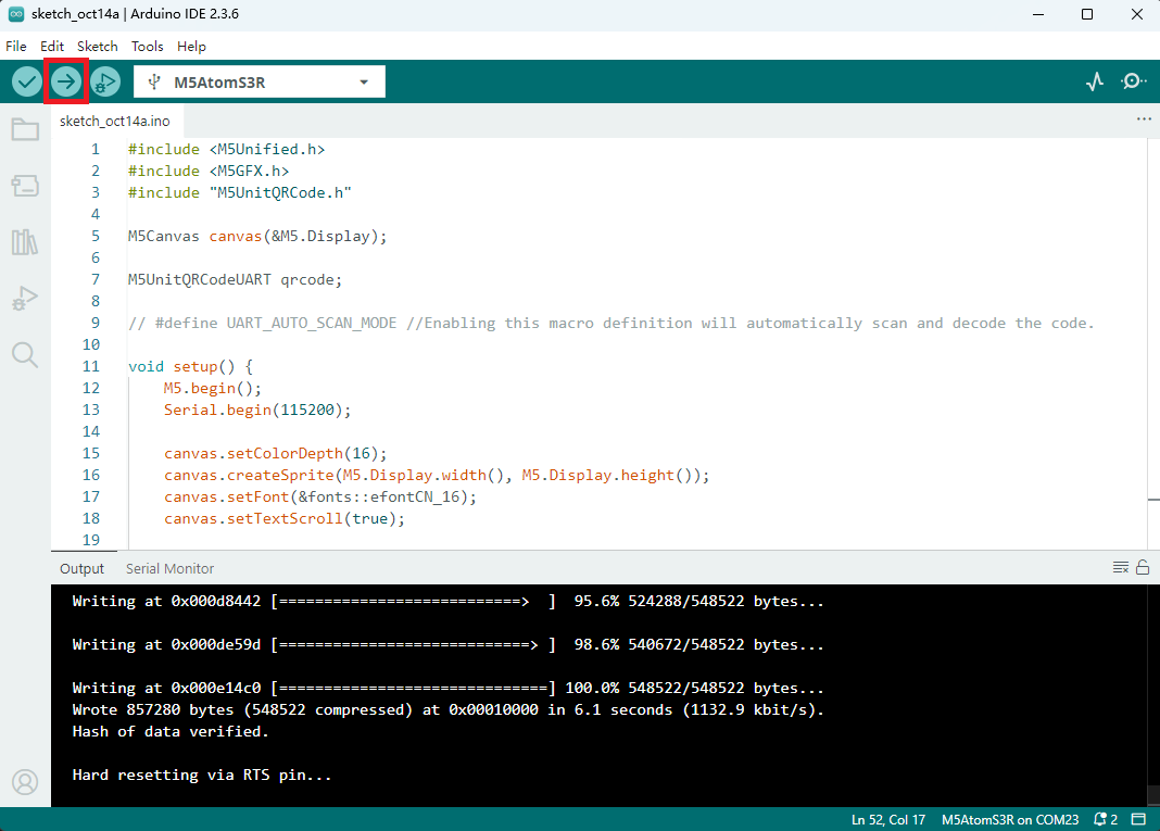
1. Download mode: Different devices require different steps to enter download/programming mode before flashing. Refer to the device programming section at the bottom of the Arduino IDE Getting Started Guide for detailed steps.
For AtomS3R, press and hold the reset button for about 2 seconds until the internal green LED lights, then release. The device is now in download mode and ready for programming.
- 2. Select the device port, click the Compile & Upload button in the Arduino IDE, and wait for the program to finish compiling and uploading to the device.
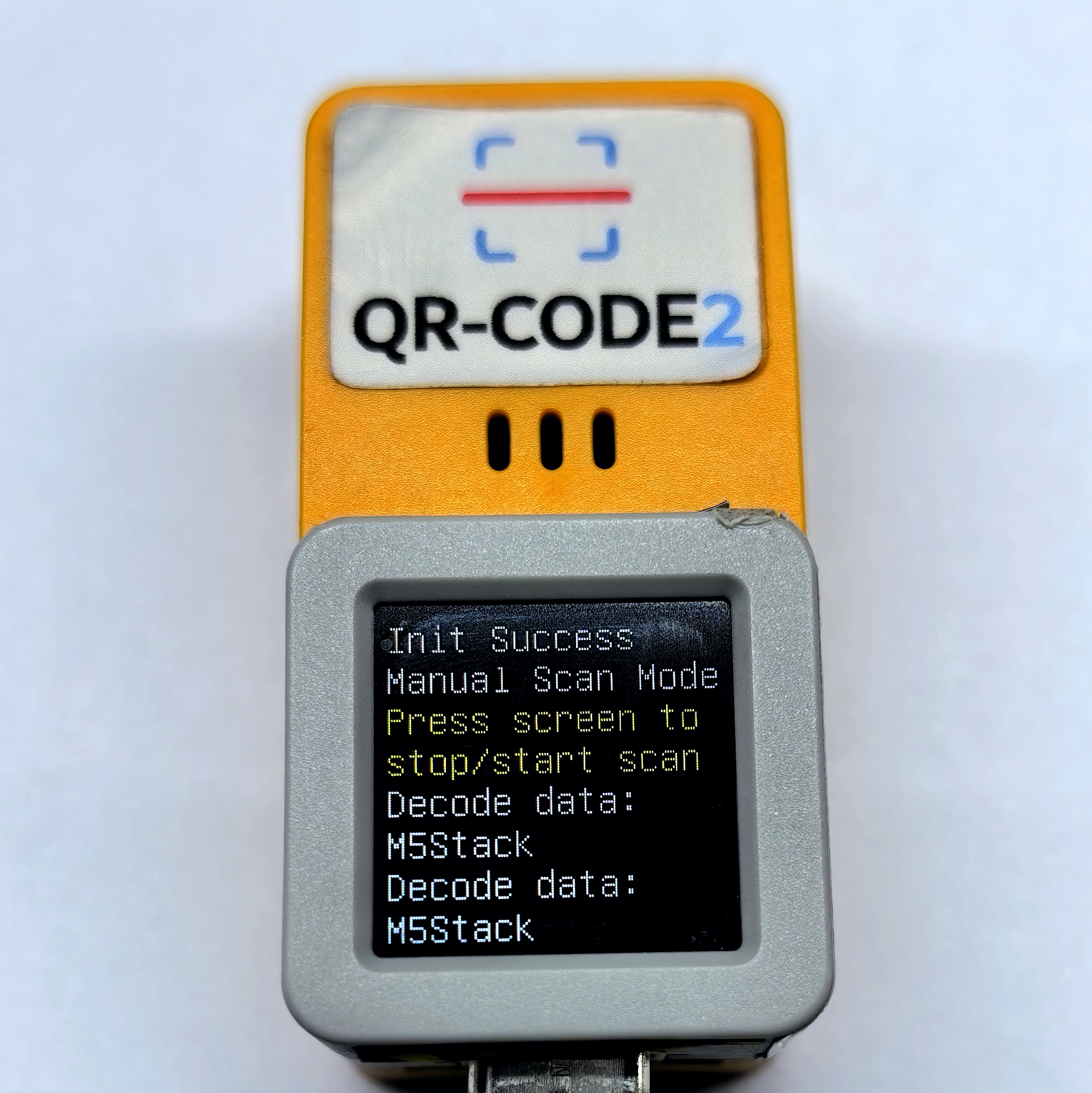
4. Scan Result Preview
- Press the host device screen to trigger a single scan/decode. Scan the QR code on the left in the example below — the result appears as in the right image.

Page Tools