

Arduino Quick Start
2. Devices & Examples
3. M5Unified
4. M5GFX
5. Extensions
Unit
Atomic
Tab5
IoT
Accessories
StamPLC AC Arduino Tutorial
1. Preparation
Environment setup: Refer to Getting Started with Arduino IDE to complete the IDE installation, and install the corresponding board manager and required driver libraries according to your development board.
Required libraries:
Required hardware products:

2. Example Program
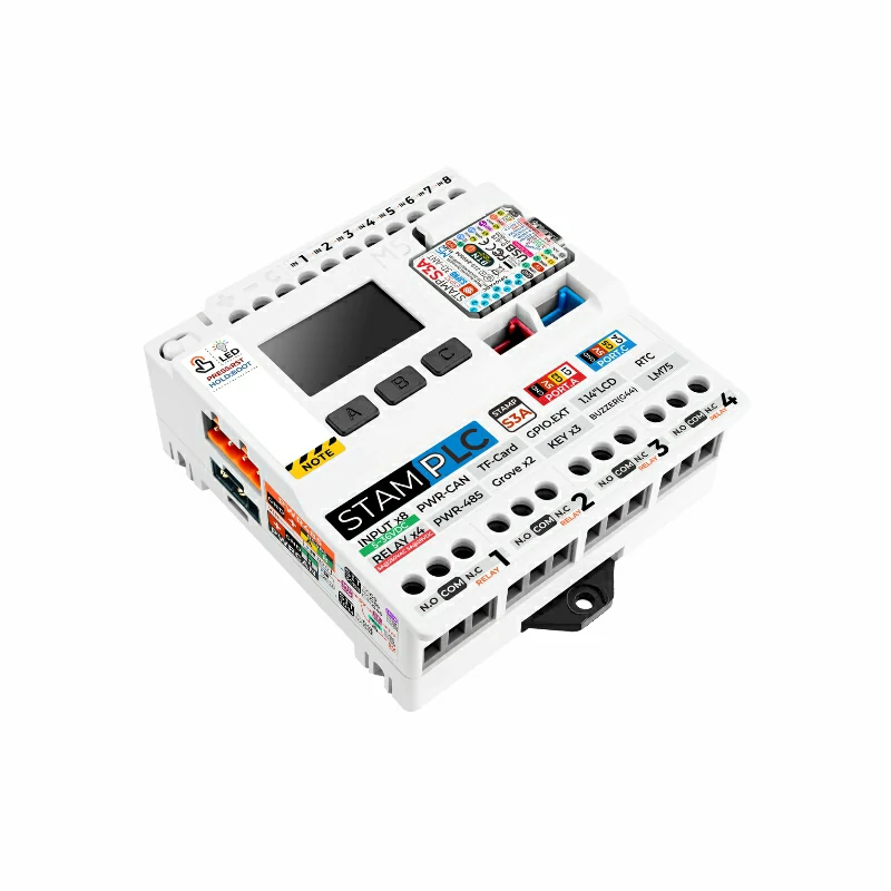
- In this tutorial, the main controller used is StamPLC, paired with StamPLC AC. StamPLC AC communicates with the host via I2C. The integrated RGB LED and relay switch are controlled by the IO expansion chip. Please modify the pin definitions in the program according to your actual circuit connection. After connecting the devices, the corresponding I2C IO are
G15 (SCL)andG13 (SDA), RGB LED IO areP5 (SYS_LEDR),P6 (SYS_LEDG),P7 (SYS_LEDB), and relay switch IO isP2 (REL_EN).
The physical connection and assembly are shown below:

cpp
1 2 3 4 5 6 7 8 9 10 11 12 13 14 15 16 17 18 19 20 21 22 23 24 25 26 27 28 29 30 31 32 33 34 35 36 37
#include "M5StamPLC.h"

M5StamPLC_AC stamplc_ac;

void setup()
{
    /* Init M5StamPLC */
    M5StamPLC.begin();
    M5StamPLC.Display.setFont(&fonts::FreeMonoBold12pt7b);
    M5StamPLC.Display.drawCenterString("StamPLC AC", 120, 60);
    /* Init M5StamPLC-AC */
    while (!stamplc_ac.begin()) {
        printf("M5StamPLC-AC init failed, retry in 1s...\n");
        delay(1000);
    }
}

void loop()
{
    static bool relay_state = false;

    /* Toggle M5StamPLC-AC relay state */
    relay_state = !relay_state;
    stamplc_ac.writeRelay(relay_state);
    printf("Write M5StamPLC-AC Relay to %s\n", stamplc_ac.readRelay() ? "ON" : "OFF");
    if (relay_state)
    {
        stamplc_ac.setStatusLight(0, 1, 0);
        printf("Set M5StamPLC-AC status light to green\n");
    }
    else
    {
        stamplc_ac.setStatusLight(1, 0, 0);
        printf("Set M5StamPLC-AC status light to red\n");
    }
    delay(1000);
}3. Compile & Upload
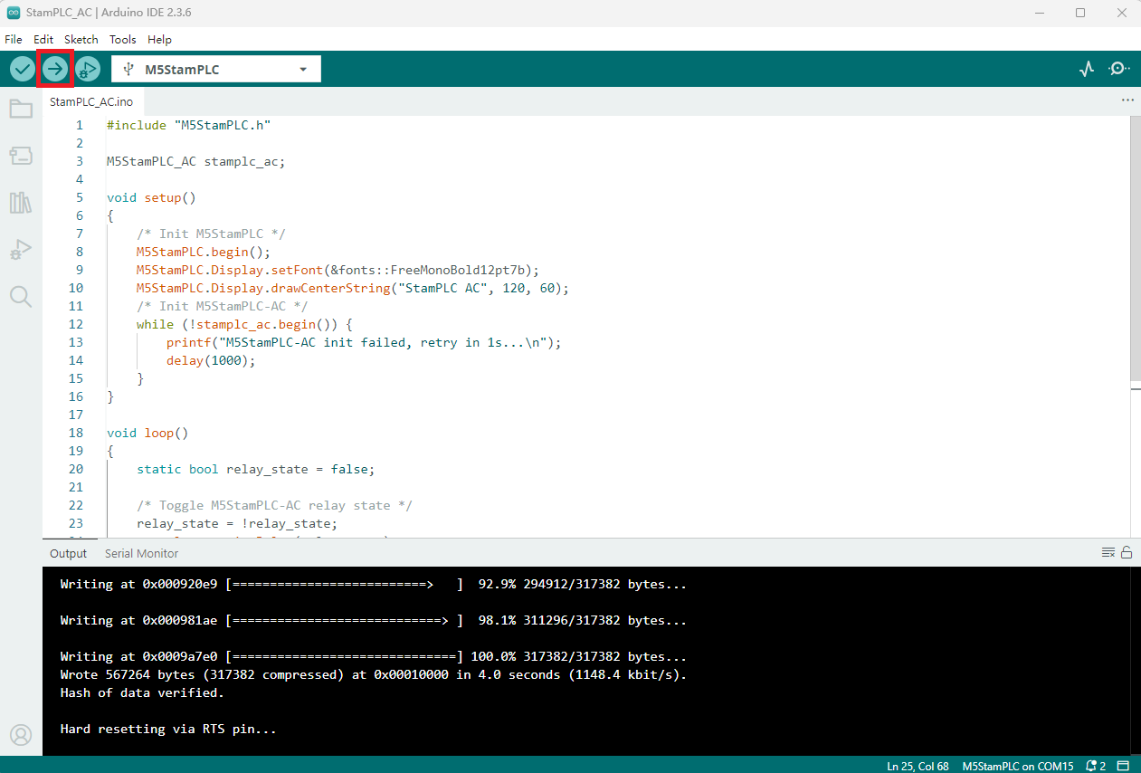
- Long press the Boot button on StamPLC, release it after the red LED lights up. The device will enter download mode and wait for flashing.
- Select the device port, click the compile and upload button in the upper left corner of Arduino IDE, and wait for the program to finish compiling and uploading to the device.
4. Relay Switch Control
- After powering on, the StamPLC will automatically initialize the StamPLC AC module and set the relay switch to the open state, with the status indicator showing red. Then, every second, the relay switch toggles its state, and the status indicator changes color accordingly: when the relay is closed, the status indicator turns green and the lamp lights up; when the relay is open, the status indicator turns red and the lamp turns off.
Serial monitor feedback is as follows:
Write M5StamPLC-AC Relay to ON
Set M5StamPLC-AC status light to green
Write M5StamPLC-AC Relay to OFF
Set M5StamPLC-AC status light to red
...Page Tools