


Arduino Quick Start
2. Devices & Examples
3. M5Unified
4. M5GFX
5. Extensions
Unit
Base
IoT
Accessories
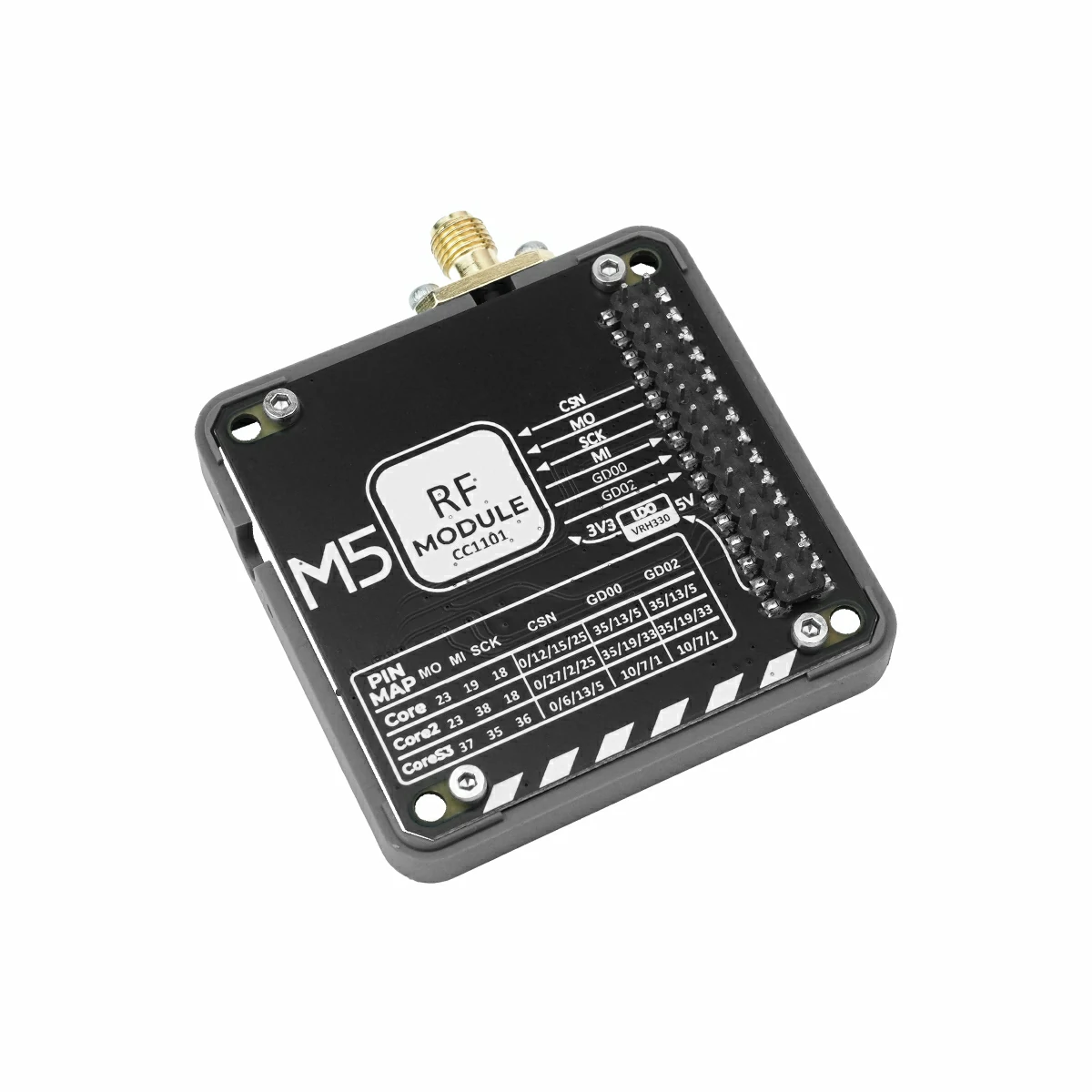
Module CC1101 Arduino Tutorial
1. Preparation
Environment Configuration: Refer to the Arduino IDE Quick Start Tutorial to complete the IDE installation, and install the corresponding board management for the development board you are using, as well as the required driver libraries.
Driver libraries used:
Hardware products used:

2. Notes
3. Example Program
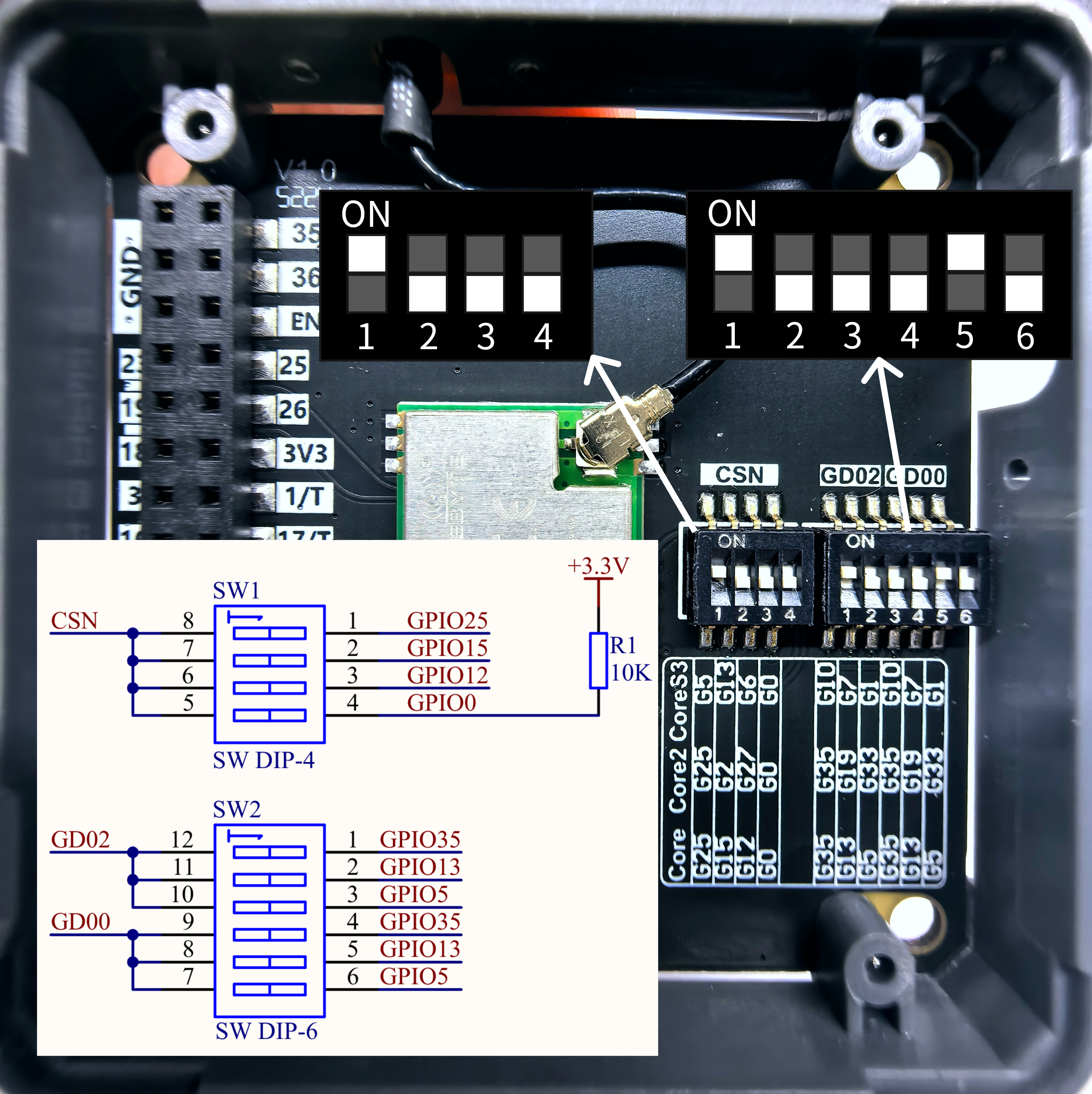
- In this tutorial, the main control device used is CoreS3, paired with Module CC1101 to implement wireless communication. Before use, please refer to the diagram below and set the pin DIP switches to the specified positions.
3.1 Pin DIP Switch
Module CC1101 communicates via SPI. Please modify the pin definitions in the program according to the actual circuit connections. After the device is connected, the corresponding SPI IO pins are G5 (CSN), G37 (MOSI), G35 (MISO), and G36 (SCK); the interrupt IO pins are G7 (GD00) and G10 (GD02). The physical setup is shown in the figure below:
3.2 Parameter Configuration
Module CC1101 supports multiple parameter configurations. Please refer to the following content for settings before use. For the meaning of each parameter and other detailed information, see the Datasheet, and adjust the parameter settings in the example program according to actual needs. Ensure that parameters are consistent between the transmitter and receiver.
Frequency (CC1101_FREQ)
This module supports 855 ~ 925 MHz band.Bit Rate (CC1101_BIT_RATE)- Calculation Formula:
Bit rate (kbps) = ((256 + DRATE_M) × 2^DRATE_E × f_xosc) / 2^28
DRATE_E: Value range 0-15, exponent of data rate
DRATE_M: Value range 0-255, mantissa of data rate
f_xosc: Crystal frequency, 26 MHz for this module - The bit rate range is several approximate discrete values between 0.6 ~ 500 kbps.
It is recommended to set it to 2.4 kbps (2400 bits/s). Higher bit rates can improve data transmission efficiency but shorten communication distance, reduce anti-interference capability, and increase the bit error rate.
- Calculation Formula:
Frequency Deviation (CC1101_FREQ_OFFSET)- Calculation Formula:
Frequency deviation (kHz) = (8 + DEVIATION_M) × 2^DEVIATION_E × (f_xosc / 2^17)
DEVIATION_E: Value range 0-7, exponent of frequency deviation
DEVIATION_M: Value range 0-7, mantissa of frequency deviation
f_xosc: Crystal frequency, 26 MHz for this module - The frequency deviation range is several approximate discrete values between 1.587 ~ 380.8 kHz.
The larger the value, the higher the distinguishability and signal anti-interference capability, but it will also increase bandwidth usage.
- Calculation Formula:
Bandwidth (CC1101_BW)- Carson Bandwidth Calculation Formula:
Bandwidth (kHz) = 2 × Frequency deviation + Bit rate - The receive filter bandwidth must be greater than or equal to the signal bandwidth. The bandwidth value calculated according to the above formula must be less than or equal to the set receive filter bandwidth; otherwise, signals cannot be received. It is recommended to reserve a 20%-30% margin.
CC1101 supports only 16 receive filter bandwidth settings: 58, 68, 81, 102, 116, 135, 162, 203, 232, 270, 325, 406, 541, 650, 812 (unit: kHz).
- Carson Bandwidth Calculation Formula:
Receive Power (CC1101_TX_POWER)- Available values: -30, -20, -15, -10, 0, 5, 7, 10 (unit: dBm)
- The larger the value, the higher the transmit power, and the longer the communication distance, but the higher the power consumption.
2. This parameter has no practical significance for the receiver and is only used to allow successful software compilation.
Preamble Length (CC1101_PREAMBLE_LEN)- Available values: 16, 24, 32, 48, 64, 96, 128, 192 (unit: bit)
- The preamble is used for the receiver to detect the start of a signal. The larger the value, the stronger the anti-interference capability, but it will increase the packet length and reduce transmission efficiency.
CSN, GD00, and GD02 pins are set. However, the RadioLib library will automatically map the remaining SPI pins (MOSI, MISO, SCK) according to the controller being used. When initialized with the M5Unified library, the default pins are defined based on the specific device. For CoreS3, they are G37 (MOSI), G35 (MISO), and G36 (SCK), so manual specification is not required.3.3 Transmitter
#include <M5Unified.h>
#include <RadioLib.h>

#define CC1101_FREQ         868.0f  // carrier frequency in MHz (float). Must match receiver
#define CC1101_BIT_RATE     2.4f    // bit rate in kbps (float). Recommend 2.4 = 2400 bits/s
#define CC1101_FREQ_OFFSET  25.4f   // frequency offset in kHz (float). FSK deviation
#define CC1101_BW           58.0    // receiver filter bandwidth in kHz (float). Must be >= signal occupied BW
#define CC1101_TX_POWER     10      // output power in dBm (must be one of allowed values: -30,-20,-15,-10,0,5,7,10)
#define CC1101_PREAMBLE_LEN 16      // preamble length in bits (supported values: 16--2 Bytes, 24--3 Bytes, 32--4 Bytes, 48--6 Bytes, 64--8 Bytes, 96--12 Bytes, 128--16 Bytes, 192--24 Bytes).

//        CC1101 PIN          CSN,       GD00,    RST(unused),    GD02
CC1101 radio = new Module(GPIO_NUM_5, GPIO_NUM_7, RADIOLIB_NC, GPIO_NUM_10);

// Tracks the result of the last transmission attempt (error code from RadioLib)
int transmissionState = RADIOLIB_ERR_NONE;
// Packet sent flag
volatile bool transmittedFlag = false;

// Special attribute for ESP8266/ESP32 to place ISR in RAM (faster interrupt response)
#if defined(ESP8266) || defined(ESP32)
ICACHE_RAM_ATTR
#endif
// This function is called when a complete packet is transmitted by the module
// IMPORTANT: this function MUST be 'void' type and MUST NOT have any arguments!
void setFlag(void)
{
    // we sent a packet, set the flag
    transmittedFlag = true;
}

void setup() {
    M5.begin();
    Serial.begin(115200);
    M5.Display.setFont(&fonts::FreeMonoBold9pt7b);

    Serial.print(F("[CC1101] Initializing ... "));
    int state = radio.begin(CC1101_FREQ, CC1101_BIT_RATE, CC1101_FREQ_OFFSET, CC1101_BW, CC1101_RX_POWER, CC1101_PREAMBLE_LEN);
    if (state == RADIOLIB_ERR_NONE) {
      Serial.println(F("Init success!"));
    } else {
      Serial.print(F("Init failed, code "));
      Serial.println(state);
      while (true) { delay(10); }
    }

    // Register callback function after sending packet successfully
    radio.setPacketSentAction(setFlag);

    // Send first packet to enable flag
    Serial.print(F("[CC1101] Sending first packet ... "));

    // you can transmit C-string or Arduino string up to
    // 255 characters long
    transmissionState = radio.startTransmit("Transmitter Ready");
    M5.Display.setCursor(5,0);
    M5.Display.printf("Transmitter Ready\n");
}

// Counter to keep track of transmitted packets
int count = 0;

void loop() {
    // check if the previous transmission finished
    if(transmittedFlag) {
        // reset flag
        transmittedFlag = false;

        if (transmissionState == RADIOLIB_ERR_NONE) {
          // packet was successfully sent
          Serial.println(F("Transmission finished!"));
          M5.Display.println("Send sucessfully!");

          // NOTE: when using interrupt-driven transmit method,
          //       it is not possible to automatically measure
          //       transmission data rate using getDataRate()

        } else {
          Serial.print(F("Send failed, code: "));
          Serial.println(transmissionState);
          M5.Display.print("\nSend failed\ncode:");
          M5.Display.println(transmissionState);
        }

        // clean up after transmission is finished
        // this will ensure transmitter is disabled,
        // RF switch is powered down etc.
        radio.finishTransmit();

        // wait a second before transmitting again
        delay(1000);

        Serial.printf("[CC1101] Sending #%d packet ... ", count);
        // you can transmit C-string or Arduino string up to 255 characters long
        String str = "Module CC1101 #" + String(count);
        transmissionState = radio.startTransmit(str);
        M5.Display.clear();
        M5.Display.setCursor(0,5);
        M5.Display.printf("[CC1101]\nSending #%d packet......\n", count++);

        // you can also transmit byte array up to 255 bytes long with limitations https://github.com/jgromes/RadioLib/discussions/1138
        /*
          byte byteArr[] = {0x01, 0x23, 0x45, 0x67,
                            0x89, 0xAB, 0xCD, 0xEF};
          int state = radio.startTransmit(byteArr, 8);
        */
    }
}3.4 Receiver
#include <M5Unified.h>
#include <RadioLib.h>

#define CC1101_FREQ         868.0f  // carrier frequency in MHz (float). Must match transmitter
#define CC1101_BIT_RATE     2.4f    // bit rate in kbps (float). Recommend 2.4 = 2400 bits/s
#define CC1101_FREQ_OFFSET  25.4f   // frequency offset in kHz (float). FSK deviation
#define CC1101_BW           58.0    // receiver filter bandwidth in kHz (float). Must beyond signal occupied BW
#define CC1101_PREAMBLE_LEN 16      // preamble length in bits (supported values: 16--2 Bytes, 24--3 Bytes, 32--4 Bytes, 48--6 Bytes, 64--8 Bytes, 96--12 Bytes, 128--16 Bytes, 192--24 Bytes).

M5Canvas canvas(&M5.Lcd);

//        CC1101 PIN          CSN,       GD00,    RST(unused),    GD02
CC1101 radio = new Module(GPIO_NUM_5, GPIO_NUM_7, RADIOLIB_NC, GPIO_NUM_10);

// Packet received flag
volatile bool receivedFlag = false;

// Special attribute for ESP8266/ESP32 to place ISR in RAM (faster interrupt response)
#if defined(ESP8266) || defined(ESP32)
  ICACHE_RAM_ATTR
#endif
// This function is called when a complete packet is received by the module
// IMPORTANT: this function MUST be 'void' type and MUST NOT have any arguments!
void setFlag(void) {
    // we got a packet, set the flag
    receivedFlag = true;
}

void setup() {
    M5.begin();
    Serial.begin(115200);
    canvas.createSprite(320, 240);
    canvas.setFont(&fonts::FreeMonoBold9pt7b);

    Serial.print(F("[CC1101] Initializing ... "));
    int state = radio.begin(CC1101_FREQ, CC1101_BIT_RATE, CC1101_FREQ_OFFSET, CC1101_BW, CC1101_RX_POWER, CC1101_PREAMBLE_LEN);
    if (state == RADIOLIB_ERR_NONE) {
      Serial.println(F("success!"));
    } else {
      Serial.print(F("failed, code "));
      Serial.println(state);
      while (true) { delay(10); }
    }

    // Register callback function after receiving packet successfully
    radio.setPacketReceivedAction(setFlag);

    // Start listening for packets
    Serial.print(F("[CC1101] Starting to listen ... "));
    state = radio.startReceive();
    if (state == RADIOLIB_ERR_NONE) {
      Serial.println(F("success!"));
    } else {
      Serial.print(F("failed, code "));
      Serial.println(state);
      while (true) { delay(10); }
    }

    // if needed, 'listen' mode can be disabled by calling
    // any of the following methods:
    //
    // radio.standby()
    // radio.sleep()
    // radio.transmit();
    // radio.receive();
    // radio.readData();
}

void loop() {
    // check if the flag is set
    if(receivedFlag) {
        // reset flag
        receivedFlag = false;

        // you can read received data as an Arduino String
        String str;
        int length = radio.getPacketLength();
        int state = radio.readData(str, length);

        // you can also read received data as byte array
        /*
          byte byteArr[8];
          int numBytes = radio.getPacketLength();
          int state = radio.readData(byteArr, numBytes);
        */

        if (state == RADIOLIB_ERR_NONE) {
          // Packet was successfully received
          Serial.println(F("[CC1101] Received packet:"));
          canvas.clear();
          canvas.setCursor(0,5);
          canvas.printf("[CC1101]\nReceived packet:\n");

          // Data of the packet
          Serial.print(F("[CC1101] Data:\t\t"));
          Serial.println(str);
          canvas.printf("Data: %s\n", str.c_str());

          // RSSI (Received Signal Strength Indicator)
          Serial.print(F("[CC1101] RSSI:\t\t"));
          Serial.print(radio.getRSSI());
          Serial.println(F(" dBm"));
          canvas.printf("RSSI: %0.2f dBm\n", radio.getRSSI());

          // LQI (Link Quality Indicator), lower is better
          Serial.print(F("[CC1101] LQI:\t\t"));
          Serial.println(radio.getLQI());
          canvas.printf("LQI:  %d\n", radio.getLQI());
          canvas.pushSprite(0, 0);

          radio.finishReceive();

        } else if (state == RADIOLIB_ERR_CRC_MISMATCH) {
          // Packet was received, but is malformed
          Serial.println(F("CRC error!"));
        } else {
          Serial.print(F("failed, code "));
          Serial.println(state);
        }
        // Put module back to listen mode
        radio.startReceive();
    }
}4. Compile and Upload
- Download Mode: Before flashing the program on different devices, you need to enter download mode. This step may vary depending on the main control device. For details, refer to the list of device program download tutorials at the bottom of the Arduino IDE Quick Start Tutorial page to see the specific operation method.
- For CoreS3, press and hold the reset button (for about 2 seconds) until the internal green LED lights up, then release. At this point, the device has entered download mode and is ready for flashing.
.gif)
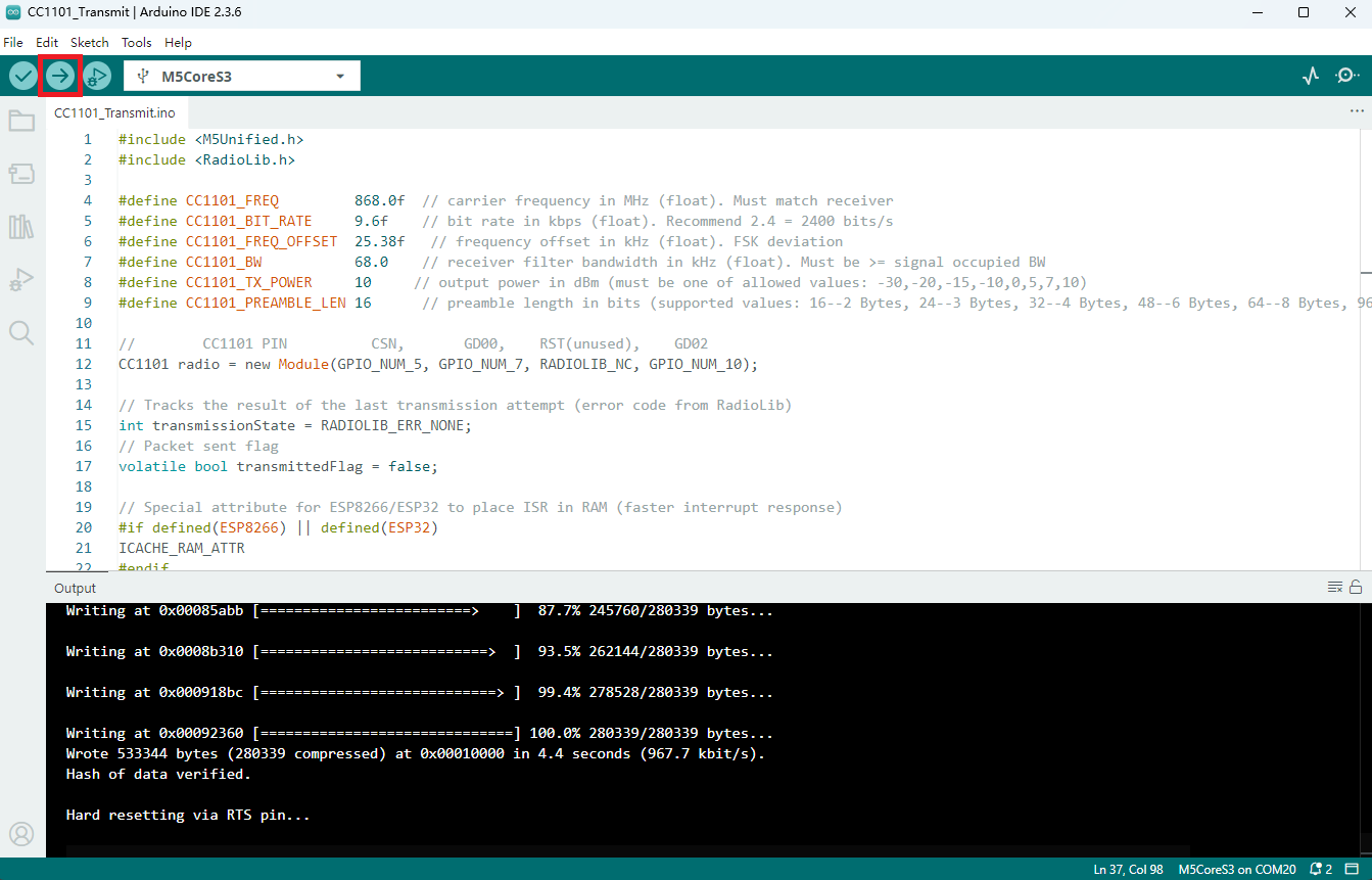
- Select the device port, click the Compile and Upload button in the upper left of Arduino IDE, and wait for the program to complete compilation and upload to the device.
5. Information Transmission and Reception Demonstration
The above example shows that the transmitter sends a string containing a counter once per second, while the receiver prints the received string and displays RSSI and other information.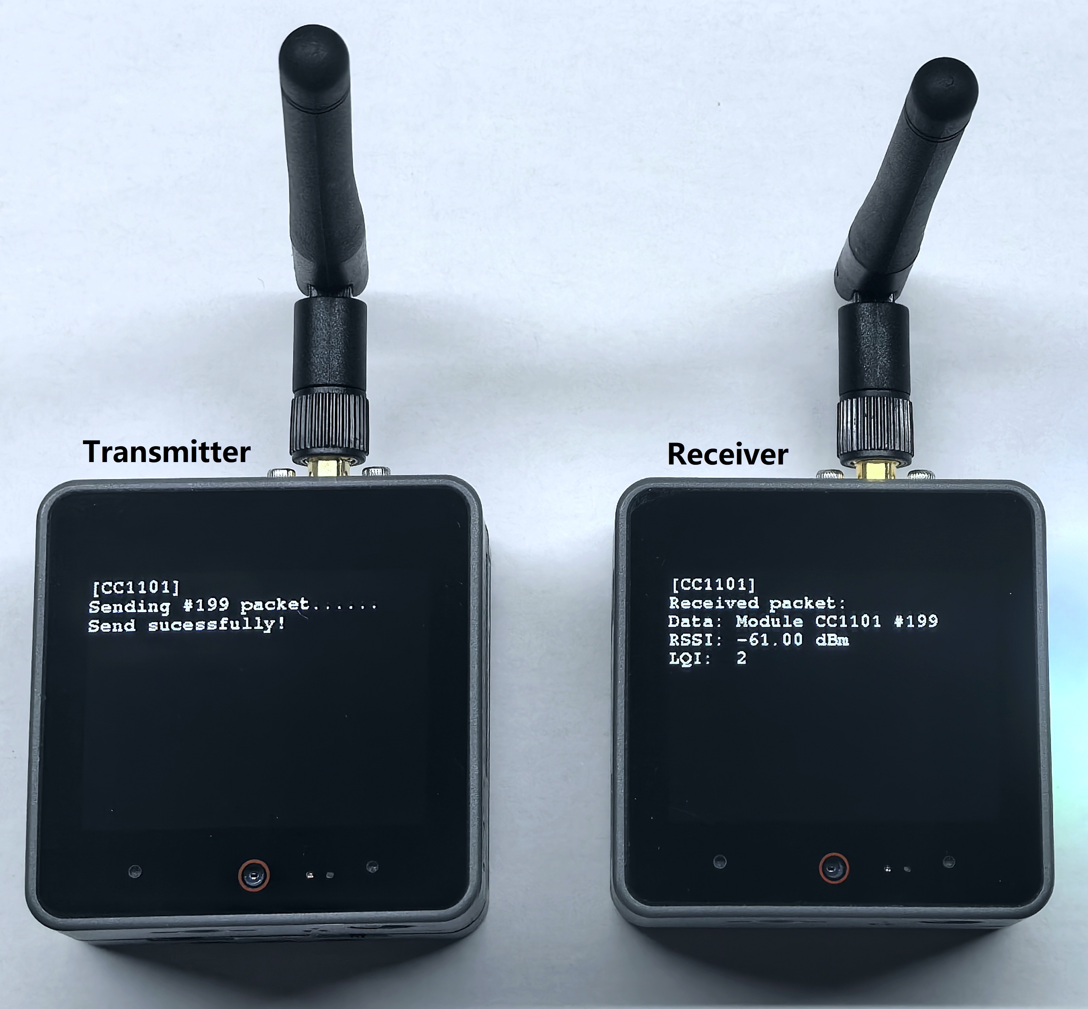
- Transmitter serial output:
[CC1101] Sending #199 packet ... Transmission finished! - Receiver serial output:
[CC1101] Received packet:
[CC1101] Data:            Module CC1101 #199
[CC1101] RSSI:            -61.00 dBm
[CC1101] LQI:             2