


Arduino Quick Start
2. Devices & Examples
3. M5Unified
4. M5GFX
5. Extensions
Unit
Base
IoT
Accessories
Atomic PWM Base Arduino Tutorial
1. Preparation
Environment Configuration: Refer to the Arduino IDE Quick Start Tutorial to install the IDE, add the board manager entries for your board, and install any required drivers and libraries.
Required driver libraries:
Hardware used:

2. Example
- In this tutorial the main controller is the AtomS3 paired with the Atomic PWM Base. The PWM output pin is
G5 (SIGNAL).
cpp
1 2 3 4 5 6 7 8 9 10 11 12 13 14 15 16 17 18 19 20 21 22 23 24 25 26 27 28 29
#include "M5Unified.h"

#define SIGNAL 5 // PWM signal output pin

int freq        = 10000; // 10kHz
int resolution  = 10;    // Duty cycle resolution in bits (10-bit = 0 to 1023)

void setup() {
    M5.begin();

    M5.Display.setTextColor(GREEN);
    M5.Display.setTextDatum(middle_center);
    M5.Display.setFont(&fonts::Orbitron_Light_24);
    M5.Display.drawString("PWM", M5.Display.width() / 2, M5.Display.height() / 2);

    ledcAttach(SIGNAL, freq, resolution);// Bind the pin, frequency, and resolution
}

void loop() {
    for (int i = 0; i < 500; i++) {
        ledcWrite(SIGNAL, i);// Update the PWM duty cycle
        delay(2);
    }

    for (int i = 500; i > 0; i--) {
        ledcWrite(SIGNAL, i);
        delay(2);
    }
}3. Compile and Upload
- 1. To enter download mode on AtomS3: press and hold the reset button for about 2 seconds until the internal green LED lights, then release — the device will enter download mode and is ready for flashing.
Note
Different devices require different steps to enter download mode before flashing. See the device-specific download instructions at the bottom of the Arduino IDE Quick Start Tutorial page for details.
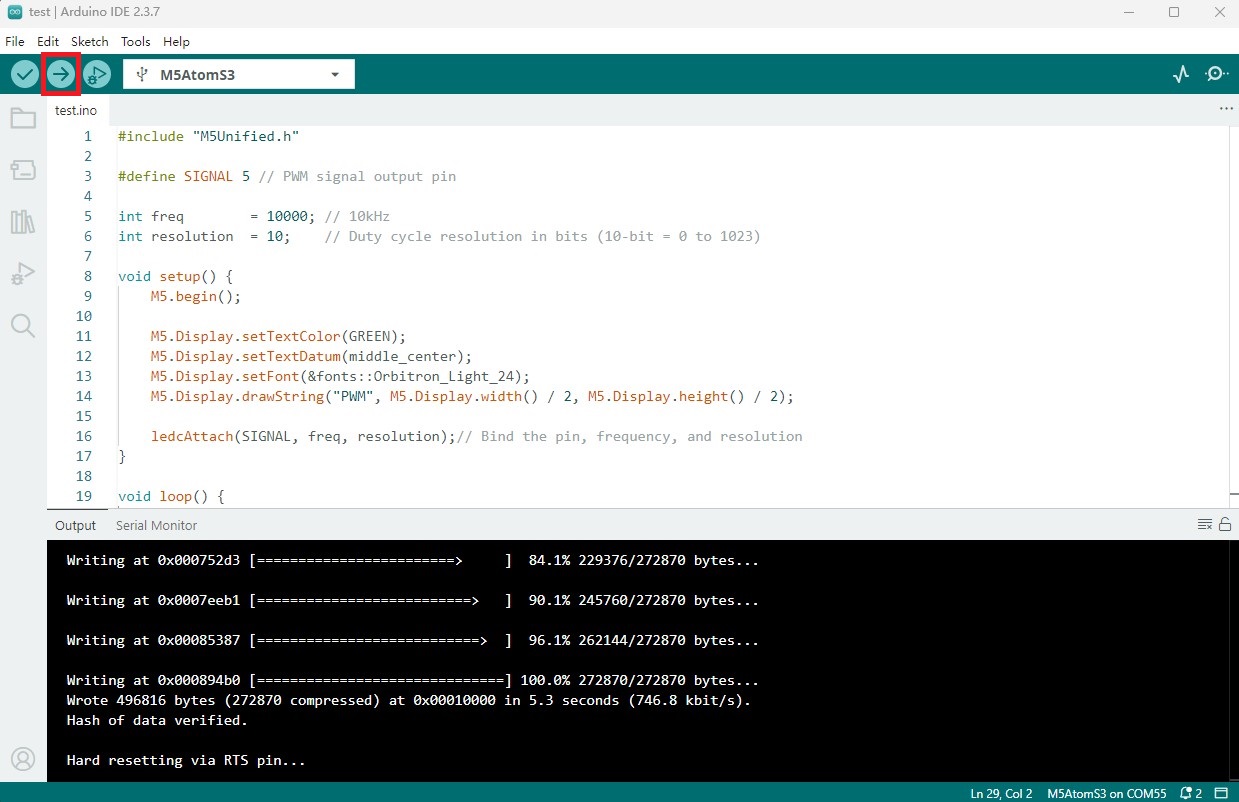
- 2. Select the device port, then click the compile & upload button in the Arduino IDE (top-left). Wait for the sketch to finish compiling and uploading to the device.
4. PWM output to control LED strip brightness
- After power-up the device will start outputting the PWM signal. The LED strip will gradually brighten, then dim, and repeat the cycle.