

Arduino 上手教程
2. 设备开发 & 案例程序
3. M5Unified
4. M5GFX
5. 拓展模块
Unit
Atomic
Tab5
IoT
NanoC6 Zigbee Arduino
NanoC6 Zigbee Arduino 相关案例程序。
准备工作
编译要求
- M5Stack 板管理版本 >= 3.2.5
- 开发板选项 = M5NanoC6
Zigbee 恒温器 (协调器)
这个例程展示了如何配置 Zigbee 协调器 (Coordinator) 并将其用作恒温器来实现以下功能:
- 作为 Zigbee 协调器运行
- 接收温度传感器数据
- 配置温度传感器的报告间隔
- 串口打印温度和配置信息
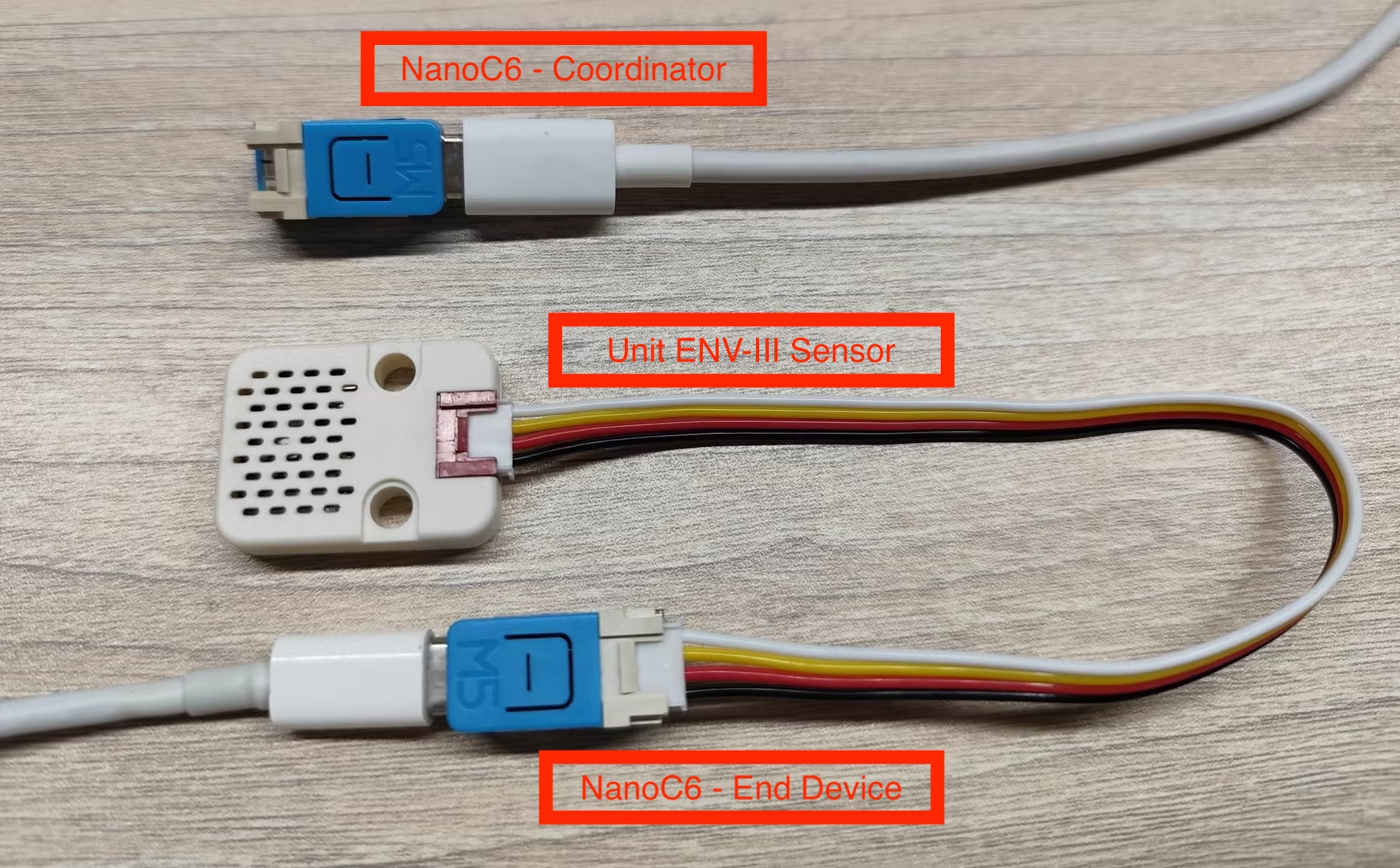
硬件要求
- 一块 NanoC6 作为 Zigbee 协调器(运行此恒温器例程)
- 一块 NanoC6 作为 Zigbee 终端设备(运行温度传感器例程)
- 一块 Unit ENV-III (测量环境温度)
配置说明
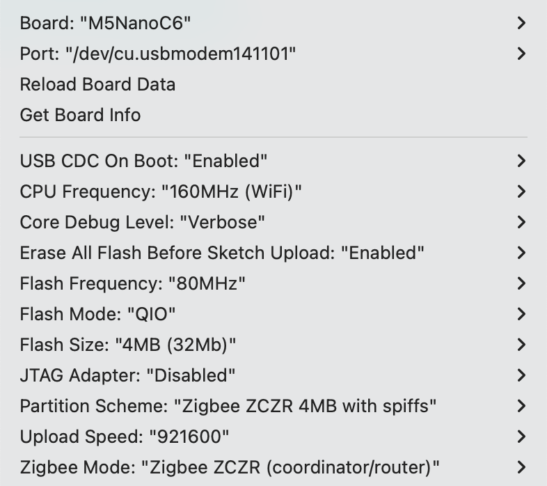
Arduino IDE 工具菜单配置:
- 选择正确的开发板:
Tools -> Board: M5NanoC6 - 选择 USB 串口启动使能:
Tools -> USB CDC On Boot: Enabled - 选择开启擦除:
Tools -> Erase All Flash Before Sketch Upload: Enabled(不开启可能导致连接失败) - 选择 flash 大小:
Tools -> Flash Size: 4MB - 选择 Zigbee 分区方案:
Tools -> Partition Scheme: Zigbee ZCZR 4MB with spiffs - 选择协调器模式:
Tools -> Zigbee mode: Zigbee ZCZR (coordinator/router) - 选择正确的串口:
Tools -> Port
案例程序
cpp
1 2 3 4 5 6 7 8 9 10 11 12 13 14 15 16 17 18 19 20 21 22 23 24 25 26 27 28 29 30 31 32 33 34 35 36 37 38 39 40 41 42 43 44 45 46 47 48 49 50 51 52 53 54 55 56 57 58 59 60 61 62 63 64 65 66 67 68 69 70 71 72 73 74 75 76 77 78 79 80 81 82 83 84 85 86 87 88 89 90 91 92 93
#ifndef ZIGBEE_MODE_ZCZR
#error "Zigbee coordinator mode is not selected in Tools->Zigbee mode"
#endif

#include "Zigbee.h"

// 定义端点编号
#define THERMOSTAT_ENDPOINT_NUMBER 5

// 创建 Zigbee 温控器对象(用于接收温度数据)
ZigbeeThermostat zbThermostat = ZigbeeThermostat(THERMOSTAT_ENDPOINT_NUMBER);

// 温度数据变量
float sensor_temp = 0.0;
float sensor_max_temp = 120.0;
float sensor_min_temp = -40.0;
float sensor_tolerance = 1.0;

// 温度接收回调函数
void receiveSensorTemp(float temperature) {
    Serial.printf("Temperature received: %.2f°C\n", temperature);
    sensor_temp = temperature;
}

// 传感器配置接收回调函数
void receiveSensorConfig(float min_temp, float max_temp, float tolerance) {
    Serial.printf("Sensor config: min=%.2f°C, max=%.2f°C, tolerance=%.2f°C\n",
                   min_temp, max_temp, tolerance);
    sensor_min_temp = min_temp;
    sensor_max_temp = max_temp;
    sensor_tolerance = tolerance;
}

void setup() {
    Serial.begin(115200);
    delay(1000);
    Serial.println("=== NanoC6 Zigbee Coordinator ===");

    // 设置回调函数
    zbThermostat.onTempReceive(receiveSensorTemp);
    zbThermostat.onConfigReceive(receiveSensorConfig);

    // 配置设备信息
    zbThermostat.setManufacturerAndModel("Espressif", "ZigbeeThermostat");

    // 添加端点
    Zigbee.addEndpoint(&zbThermostat);

    // 开放网络 180 秒
    Zigbee.setRebootOpenNetwork(180);

    // 启动 Coordinator
    Serial.println("Starting Zigbee Coordinator...");
    if (!Zigbee.begin(ZIGBEE_COORDINATOR)) {
        Serial.println("Zigbee failed to start!");
        Serial.println("Rebooting...");
        ESP.restart();
    }

    Serial.println("Zigbee Coordinator started");
    Serial.println("Network is open for 180 seconds");
    Serial.println("Waiting for temperature sensor to bind...");

    // 等待 End Device 绑定
    while (!zbThermostat.bound()) {
        Serial.print(".");
        delay(500);
    }

    Serial.println("\nTemperature sensor bound successfully!");

    // 只配置一次报告间隔
    zbThermostat.setTemperatureReporting(0, 10, 2);
    Serial.println("Temperature reporting configured");

    // 获取传感器配置
    zbThermostat.getSensorSettings();
}

void loop() {
    // 定期打印温度数据
    static uint32_t last_print = 0;
    if (millis() - last_print > 10000) {
        last_print = millis();

        int temp_percent = (int)((sensor_temp - sensor_min_temp) /
                                 (sensor_max_temp - sensor_min_temp) * 100);
        Serial.printf("Current temperature: %.2f°C (%d%%)\n",
                      sensor_temp, temp_percent);
    }

    delay(100);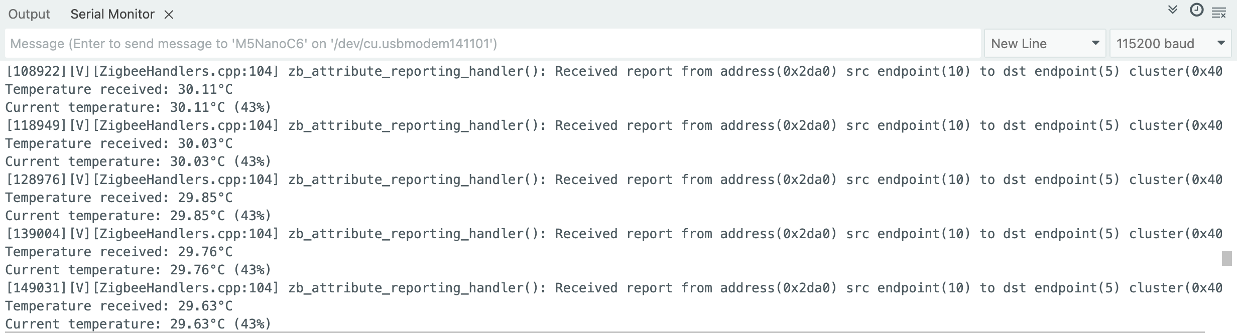
}使用步骤
- 将恒温器代码烧录到协调器 Coordinator 设备
- 将温度传感器代码烧录到终端设备 End Device
- 协调器启动后会自动创建网络并等待设备加入,每 10 秒会打印一次当前温度信息
- 查看串口监视器中的温度数据,观察温度变化时的自动报告,检查配置信息是否正确接收
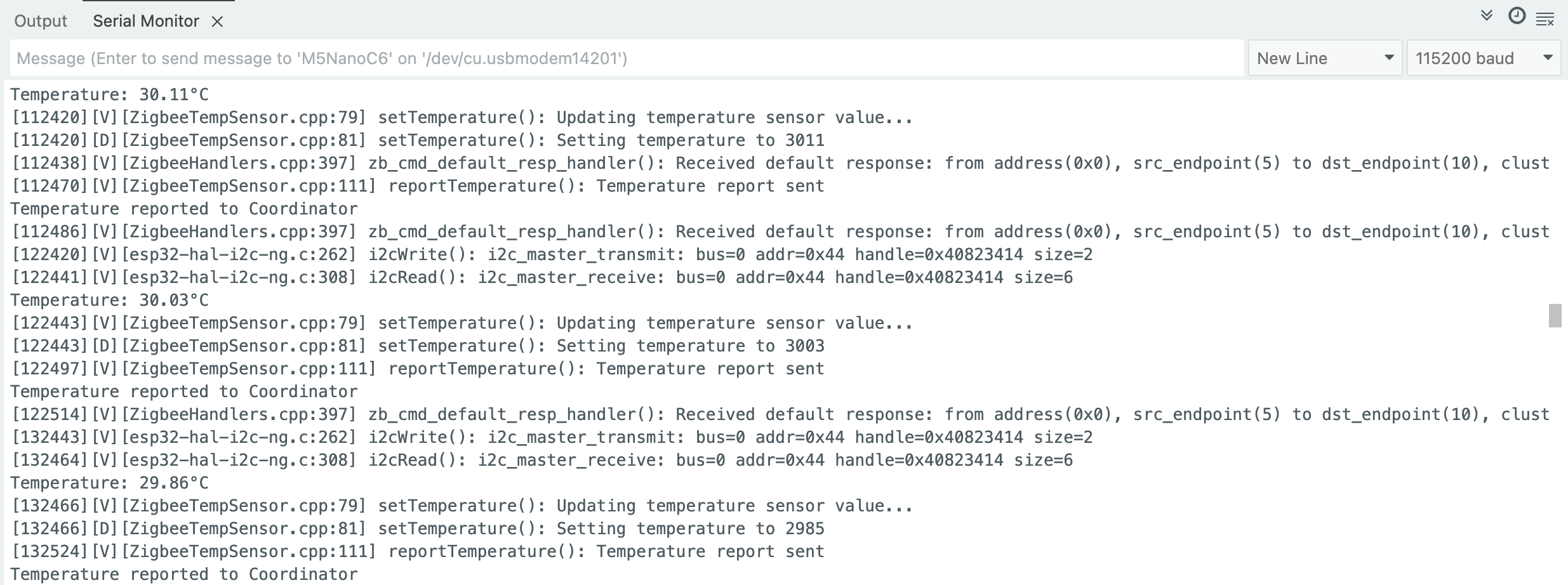
Zigbee 温度传感器
这个例程展示了如何配置 Zigbee 终端设备 (End Device) 并将其用作家庭自动化(HA)温度传感器实现以下功能:
- 作为 Zigbee 终端设备运行
- 读取芯片温度数据
- 定期向协调器报告温度
- 支持按需温度上报
配置说明
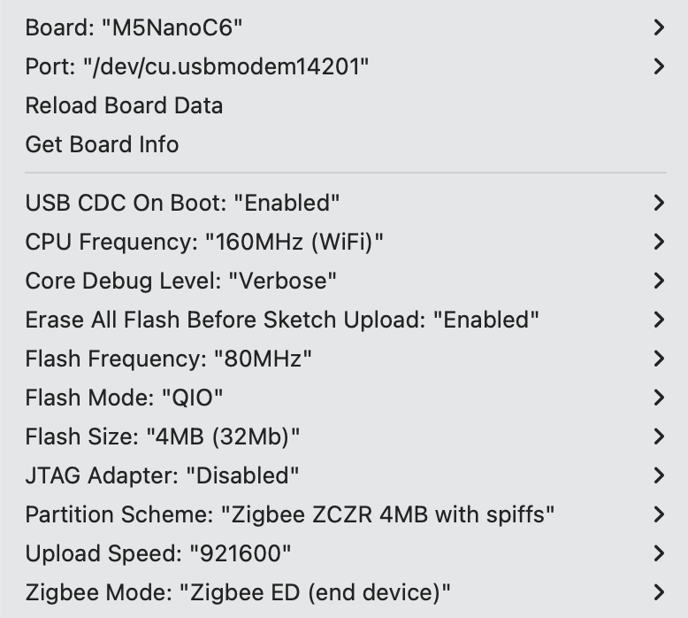
Arduino IDE 工具菜单配置:
- 选择正确的开发板:
Tools -> Board: M5NanoC6 - 选择 USB 串口启动使能:
Tools -> USB CDC On Boot: Enabled - 选择开启擦除:
Tools -> Erase All Flash Before Sketch Upload: Enabled(不开启可能导致连接失败) - 选择 flash 大小:
Tools -> Flash Size: 4MB - 选择 Zigbee 分区方案:
Tools -> Partition Scheme: Zigbee ZCZR 4MB with spiffs - 选择终端设备模式:
Tools -> Zigbee mode: Zigbee ED (end device) - 选择正确的串口:
Tools -> Port
案例程序
cpp
1 2 3 4 5 6 7 8 9 10 11 12 13 14 15 16 17 18 19 20 21 22 23 24 25 26 27 28 29 30 31 32 33 34 35 36 37 38 39 40 41 42 43 44 45 46 47 48 49 50 51 52 53 54 55 56 57 58 59 60 61 62 63 64 65 66 67 68 69 70 71 72 73 74 75 76 77 78 79 80 81 82 83 84 85 86 87 88 89 90 91 92 93 94 95 96 97 98 99 100 101 102 103 104 105 106 107 108 109 110 111 112 113 114 115 116 117 118 119 120 121 122 123 124 125 126 127 128 129 130 131 132 133 134 135 136 137 138 139 140 141 142 143 144 145 146 147 148 149 150 151 152 153 154 155 156 157 158 159 160 161 162 163 164 165 166 167 168 169 170
#ifndef ZIGBEE_MODE_ED
#error "Zigbee end device mode is not selected in Tools->Zigbee mode"
#endif

#include "Zigbee.h"
#include <Wire.h>

// 定义端点编号
#define TEMP_SENSOR_ENDPOINT_NUMBER 10

// 定义 SHT30 I2C 地址
#define SHT30_I2C_ADDR 0x44

// NanoH2 Grove 接口的 I2C 引脚
#define I2C_SDA 2   // G2 = GPIO2 (黄色线)
#define I2C_SCL 1   // G1 = GPIO1 (白色线)

// 创建 Zigbee 温度传感器对象
ZigbeeTempSensor zbTempSensor = ZigbeeTempSensor(TEMP_SENSOR_ENDPOINT_NUMBER);

// 温度数据变量
float temperature = 0.0;

// 任务同步标志
volatile bool temp_updated = false;

/************************ SHT30 温度读取函数(仅温度)*****************************/
bool readSHT30Temperature(float &temp) {
    // 发送测量命令(高重复性测量)
    Wire.beginTransmission(SHT30_I2C_ADDR);
    Wire.write(0x2C);  // 测量命令高字节
    Wire.write(0x06);  // 测量命令低字节

    if (Wire.endTransmission() != 0) {
        Serial.println("SHT30 communication failed!");
        return false;
    }

    // 等待测量完成(SHT30 需要约 15ms)
    delay(20);

    // 请求读取 6 字节数据(温度 3 字节 + 湿度 3 字节)
    Wire.requestFrom(SHT30_I2C_ADDR, 6);

    if (Wire.available() < 6) {
        Serial.println("SHT30 data not available!");
        return false;
    }

    // 读取温度数据(前 3 字节)
    uint8_t tempData[3];
    for (int i = 0; i < 3; i++) {
        tempData[i] = Wire.read();
    }

    // 跳过湿度数据(后 3 字节)
    for (int i = 0; i < 3; i++) {
        Wire.read();
    }

    // 计算温度(公式:-45 + 175 * (rawTemp / 65535))
    uint16_t rawTemp = (tempData[0] << 8) | tempData[1];
    temp = -45.0 + 175.0 * ((float)rawTemp / 65535.0);

    // 数据合理性检查
    if (temp < -40.0 || temp > 125.0) {
        Serial.printf("Invalid temperature: %.2f°C\n", temp);
        return false;
    }

    return true;
}

/************************ 温度读取任务 *****************************/
static void temp_sensor_value_update(void *arg) {
    for (;;) {
        // 读取 SHT30 温度
        if (readSHT30Temperature(temperature)) {
            Serial.printf("Temperature: %.2f°C\n", temperature);

            // 更新温度值到 Zigbee 端点
            zbTempSensor.setTemperature(temperature);

            // 设置标志,通知主循环上报
            temp_updated = true;
        } else {
            Serial.println("Failed to read SHT30");
        }

        delay(10000);  // 每 10 秒读取一次
    }
}

/********************* Arduino 主函数 ***************************/
void setup() {
    Serial.begin(115200);
    delay(1000);
    Serial.println("=== NanoC6 End Device + Unit ENV III (Temperature Only) ===");

    // 初始化 I2C(使用正确的引脚)
    Wire.begin(I2C_SDA, I2C_SCL, 100000);  // 100kHz
    Serial.printf("I2C initialized (SDA=GPIO%d, SCL=GPIO%d, 100kHz)\n",
                  I2C_SDA, I2C_SCL);

    // 增加延迟,等待总线稳定
    delay(100);

    // 测试 SHT30 连接
    Serial.println("Scanning I2C bus...");
    Wire.beginTransmission(SHT30_I2C_ADDR);
    uint8_t error = Wire.endTransmission();

    if (error == 0) {
        Serial.println("SHT30 detected at address 0x44");
    } else {
        Serial.printf("SHT30 not found! Error code: %d\n", error);
        Serial.println("\n   Expected wiring:");
        Serial.println("   - Black (GND) → GND");
        Serial.println("   - Red (5V) → 5V");
        Serial.println("   - Yellow (SDA) → G2 (GPIO2)");
        Serial.println("   - White (SCL) → G1 (GPIO1)");
        while (1) delay(1000);  // 停止运行
    }

    // 配置 Zigbee 温度传感器
    zbTempSensor.setManufacturerAndModel("Espressif", "TempSensor");
    zbTempSensor.setMinMaxValue(-40, 120);  // 设置温度范围
    zbTempSensor.setTolerance(1);  // 设置容差 ±1°C

    // 添加端点到 Zigbee 核心
    Zigbee.addEndpoint(&zbTempSensor);

    // 启动 Zigbee End Device
    Serial.println("Starting Zigbee End Device...");
    if (!Zigbee.begin()) {
        Serial.println("Zigbee failed to start!");
        Serial.println("Rebooting in 5 seconds...");
        delay(5000);
        ESP.restart();
    }

    Serial.println("Zigbee End Device started");
    Serial.println("Connecting to network...");

    // 等待连接到 Zigbee 网络
    while (!Zigbee.connected()) {
        Serial.print(".");
        delay(1000);
    }

    Serial.println("\nConnected to Zigbee network!");

    // 创建温度读取任务(栈大小 4096 字节)
    xTaskCreate(temp_sensor_value_update, "temp_sensor_update", 4096, NULL, 10, NULL);

    // 配置报告间隔
    zbTempSensor.setReporting(1, 0, 1);
    Serial.println("Temperature reporting configured");
}

void loop() {
    // 只在温度更新时上报
    if (temp_updated) {
        temp_updated = false;
        zbTempSensor.reportTemperature();
        Serial.println("Temperature reported to Coordinator");
    }

    delay(100);
}使用步骤
- 确保协调器已经运行并创建网络,将温度传感器代码烧录到终端设备
- 设备启动后会自动搜索并加入网络,每 10 秒读取一次温度数据,当温度变化超过 0.01°C 时自动上报
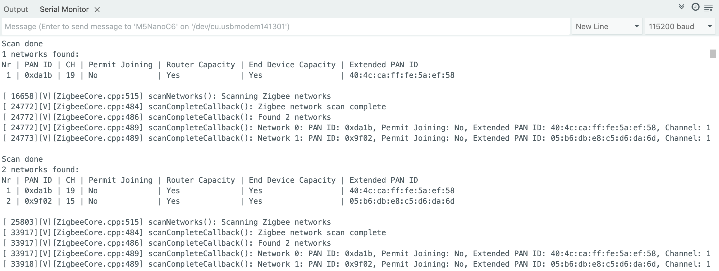
Zigbee 网络扫描
这个例程展示了扫描周围的 Zigbee 网络,并打印网络信息至串口。
- 确保周围有活跃的 Zigbee 网络,将扫描代码烧录到设备
- 设备启动后自动开始扫描,每次扫描完成后显示结果,并自动开始下一轮扫描
案例程序
cpp
1 2 3 4 5 6 7 8 9 10 11 12 13 14 15 16 17 18 19 20 21 22 23 24 25 26 27 28 29 30 31 32 33 34 35 36 37 38 39 40 41 42 43 44 45 46 47 48 49 50 51 52 53 54 55 56 57 58 59 60 61 62 63 64 65 66 67 68 69 70 71 72 73 74 75 76 77 78 79 80 81 82
#if !defined(ZIGBEE_MODE_ED) && !defined(ZIGBEE_MODE_ZCZR)
#error "Zigbee device mode is not selected in Tools->Zigbee mode"
#endif

#include "Zigbee.h"

#ifdef ZIGBEE_MODE_ZCZR
zigbee_role_t role = ZIGBEE_ROUTER;  // or can be ZIGBEE_COORDINATOR, but it won't scan itself
#else
zigbee_role_t role = ZIGBEE_END_DEVICE;
#endif

void printScannedNetworks(uint16_t networksFound) {
    if (networksFound == 0) {
        Serial.println("No networks found");
    } else {
        zigbee_scan_result_t *scan_result = Zigbee.getScanResult();
        Serial.println("\nScan done");
        Serial.print(networksFound);
        Serial.println(" networks found:");
        Serial.println("Nr | PAN ID | CH | Permit Joining | Router Capacity | End Device Capacity | Extended PAN ID");
        for (int i = 0; i < networksFound; ++i) {
        // Print all available info for each network found
        Serial.printf("%2d", i + 1);
        Serial.print(" | ");
        Serial.printf("0x%04hx", scan_result[i].short_pan_id);
        Serial.print(" | ");
        Serial.printf("%2d", scan_result[i].logic_channel);
        Serial.print(" | ");
        Serial.printf("%-14.14s", scan_result[i].permit_joining ? "Yes" : "No");
        Serial.print(" | ");
        Serial.printf("%-15.15s", scan_result[i].router_capacity ? "Yes" : "No");
        Serial.print(" | ");
        Serial.printf("%-19.19s", scan_result[i].end_device_capacity ? "Yes" : "No");
        Serial.print(" | ");
        Serial.printf(
            "%02x:%02x:%02x:%02x:%02x:%02x:%02x:%02x", scan_result[i].extended_pan_id[7], scan_result[i].extended_pan_id[6], scan_result[i].extended_pan_id[5],
            scan_result[i].extended_pan_id[4], scan_result[i].extended_pan_id[3], scan_result[i].extended_pan_id[2], scan_result[i].extended_pan_id[1],
            scan_result[i].extended_pan_id[0]
        );
        Serial.println();
        delay(10);
        }
        Serial.println("");
        // Delete the scan result to free memory for code below.
        Zigbee.scanDelete();
    }
}

void setup() {
    Serial.begin(115200);

    // Initialize Zigbee stack without any EPs just for scanning
    if (!Zigbee.begin(role)) {
        Serial.println("Zigbee failed to start!");
        Serial.println("Rebooting...");
        ESP.restart();
    }

    Serial.println("Setup done, starting Zigbee network scan...");
    // Start Zigbee Network Scan with default parameters (all channels, scan time 5)
    Zigbee.scanNetworks();
}

void loop() {
    // check Zigbee Network Scan process
    int16_t ZigbeeScanStatus = Zigbee.scanComplete();
    if (ZigbeeScanStatus < 0) {  // it is busy scanning or got an error
        if (ZigbeeScanStatus == ZB_SCAN_FAILED) {
        Serial.println("Zigbee scan has failed. Starting again.");
        delay(1000);
        Zigbee.scanNetworks();
        }
        delay(100);
        // other option is status ZB_SCAN_RUNNING - just wait.
    } else {  // Found Zero or more Wireless Networks
        printScannedNetworks(ZigbeeScanStatus);
        delay(1000);
        Zigbee.scanNetworks();  // start over...
    }
    // Loop can do something else...
}使用步骤
- 确保周围有活跃的 Zigbee 网络,将扫描代码烧录到设备
- 设备启动后自动开始扫描,每次扫描完成后显示结果,并自动开始下一轮扫描
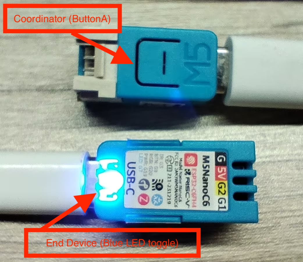
Zigbee Switch (协调器)
这个例程展示了如何配置 Zigbee 协调器 (Coordinator), 检测 ButtonA 来控制终端设备 (End device) 的蓝色 LED 灯开关,并实现以下功能:
- 作为 Zigbee 协调器运行
- 检测 ButtonA 是否被按下
- 指令终端设备 (End device) 的蓝色 LED 灯开关
- 串口打印指令信息
硬件要求
- 一块 NanoC6 作为 Zigbee 协调器 (Switch)
- 一块 NanoC6 作为 Zigbee 终端设备 (Blue LED toggle)
配置说明
Arduino IDE 工具菜单配置:
- 选择正确的开发板:
Tools -> Board: M5NanoC6 - 选择 USB 串口启动使能:
Tools -> USB CDC On Boot: Enabled - 选择开启擦除:
Tools -> Erase All Flash Before Sketch Upload: Enabled(不开启可能导致连接失败) - 选择 flash 大小:
Tools -> Flash Size: 4MB - 选择 Zigbee 分区方案:
Tools -> Partition Scheme: Zigbee ZCZR 4MB with spiffs - 选择协调器模式:
Tools -> Zigbee mode: Zigbee ZCZR (coordinator/router) - 选择正确的串口:
Tools -> Port
案例程序
cpp
1 2 3 4 5 6 7 8 9 10 11 12 13 14 15 16 17 18 19 20 21 22 23 24 25 26 27 28 29 30 31 32 33 34 35 36 37 38 39 40 41 42 43 44 45 46 47 48 49 50 51 52 53 54 55 56 57 58 59 60 61 62 63 64 65 66 67 68 69 70 71 72 73 74 75 76 77 78 79 80 81 82 83 84
#ifndef ZIGBEE_MODE_ZCZR
#error "Zigbee coordinator mode is not selected in Tools->Zigbee mode"
#endif

#include "Zigbee.h"

#define SWITCH_ENDPOINT_NUMBER 5

// ButtonA Pin(GPIO9)
#define BUTTON_A_PIN 9

// Zigbee Switch (To send On/OFF command)
ZigbeeSwitch zbSwitch = ZigbeeSwitch(SWITCH_ENDPOINT_NUMBER);

// LED state
bool led_state = false;

// ButtonA debounce
unsigned long last_button_press = 0;
const unsigned long debounce_delay = 200;  // 200ms

void setup() {
    Serial.begin(115200);
    delay(1000);
    Serial.println("=== NanoC6 Zigbee Coordinator (ButtonA Controller) ===");

    pinMode(BUTTON_A_PIN, INPUT_PULLUP);
    Serial.println("ButtonA (G9/GPIO9) initialized");

    zbSwitch.setManufacturerAndModel("Espressif", "ZigbeeSwitch");

    Zigbee.addEndpoint(&zbSwitch);

    // Network open for joining for 180 secs
    Zigbee.setRebootOpenNetwork(180);

    // Setup Coordinator
    Serial.println("Starting Zigbee Coordinator...");
    if (!Zigbee.begin(ZIGBEE_COORDINATOR)) {
        Serial.println("Zigbee failed to start!");
        Serial.println("Rebooting...");
        ESP.restart();
    }

    Serial.println("Zigbee Coordinator started");
    Serial.println("Network is open for 180 seconds");
    Serial.println("Waiting for LED device to bind...");

    while (!zbSwitch.bound()) {
        Serial.print(".");
        delay(500);
    }

    Serial.println("\nLED device bound successfully!");
    Serial.println("\nPress ButtonA to toggle LED");
}

void loop() {
    // Check if ButtonA is pressed
    if (digitalRead(BUTTON_A_PIN) == LOW) {
        unsigned long current_time = millis();
        if (current_time - last_button_press > debounce_delay) {
            last_button_press = current_time;

            // Switch LED states
            led_state = !led_state;

            if (led_state) {
                Serial.println("Sending ON command...");
                zbSwitch.lightOn();
            } else {
                Serial.println("Sending OFF command...");
                zbSwitch.lightOff();
            }

            // Wait for ButtonA to release
            while (digitalRead(BUTTON_A_PIN) == LOW) {
                delay(10);
            }
        }
    }

    delay(10);
}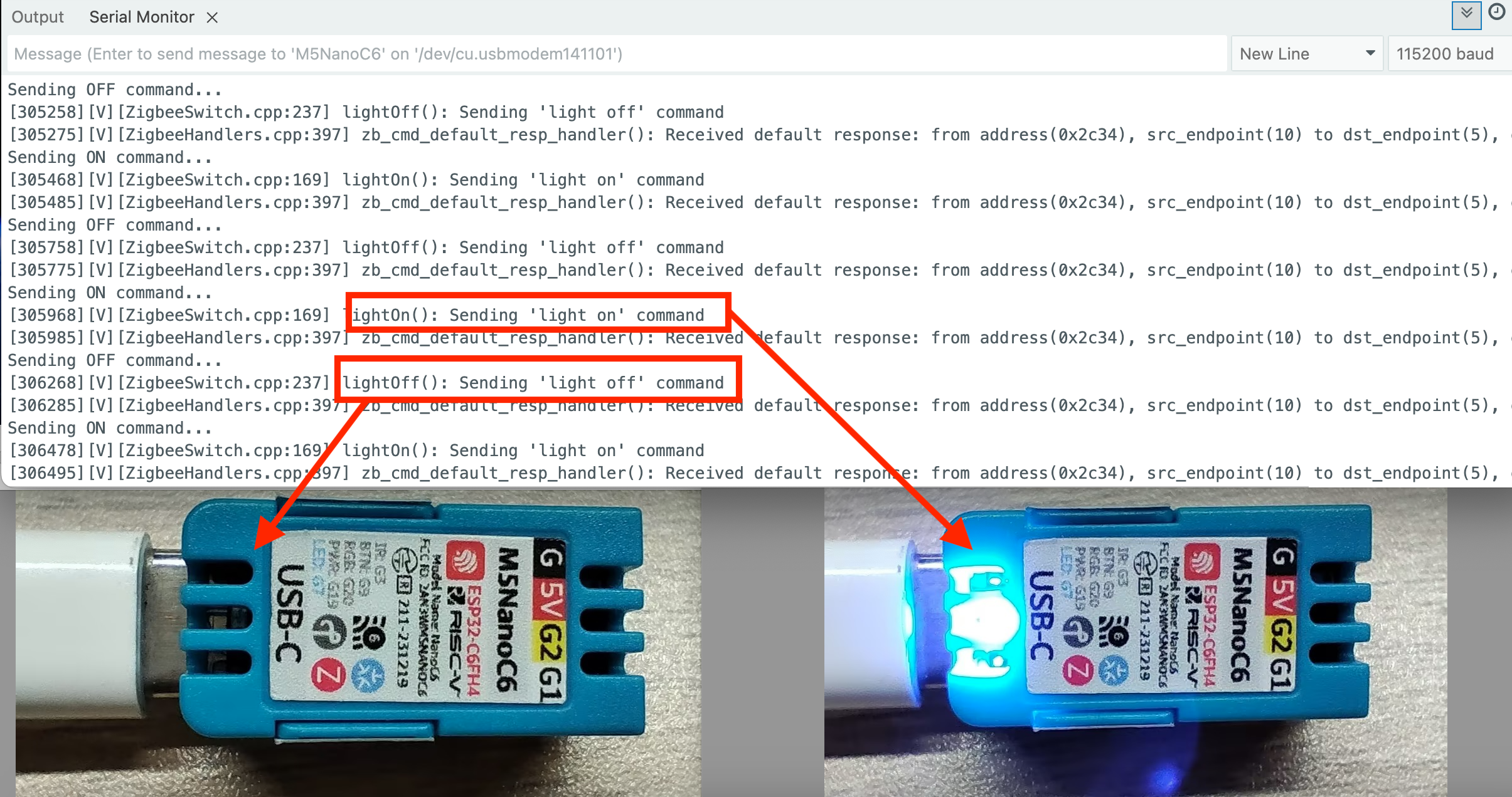
Zigbee 接受指令开关蓝色 LED 灯
这个例程展示了如何配置 Zigbee 终端设备 (End Device), 接受指令开关蓝色 LED 灯,并实现以下功能:
- 作为 Zigbee 终端设备运行
- 读取 Coordinator 传来的指令
- 串口打印接受数据
- 开关 NanoC6 上的蓝色 LED 灯
配置说明
Arduino IDE 工具菜单配置:
- 选择正确的开发板:
Tools -> Board: M5NanoC6 - 选择 USB 串口启动使能:
Tools -> USB CDC On Boot: Enabled - 选择开启擦除:
Tools -> Erase All Flash Before Sketch Upload: Enabled(不开启可能导致连接失败) - 选择 flash 大小:
Tools -> Flash Size: 4MB - 选择 Zigbee 分区方案:
Tools -> Partition Scheme: Zigbee ZCZR 4MB with spiffs - 选择终端设备模式:
Tools -> Zigbee mode: Zigbee ED (end device) - 选择正确的串口:
Tools -> Port
案例程序
cpp
1 2 3 4 5 6 7 8 9 10 11 12 13 14 15 16 17 18 19 20 21 22 23 24 25 26 27 28 29 30 31 32 33 34 35 36 37 38 39 40 41 42 43 44 45 46 47 48 49 50 51 52 53 54 55 56 57 58 59 60 61
#ifndef ZIGBEE_MODE_ED
#error "Zigbee end device mode is not selected in Tools->Zigbee mode"
#endif

#include "Zigbee.h"

#define LIGHT_ENDPOINT_NUMBER 10

// Blue LED Pin(GPIO7)
#define BLUE_LED_PIN 7

// Zigbee controlled LED (listen for On/Off command)
ZigbeeLight zbLight = ZigbeeLight(LIGHT_ENDPOINT_NUMBER);

// LED toggle
void setLED(bool state) {
    digitalWrite(BLUE_LED_PIN, state ? HIGH : LOW); // NanoC6 Blue LED is active LOW
}

void setup() {
    Serial.begin(115200);
    delay(1000);
    Serial.println("=== NanoC6 Zigbee End Device (LED) ===");

    // Set Blue LED Pin
    pinMode(BLUE_LED_PIN, OUTPUT);
    digitalWrite(BLUE_LED_PIN, HIGH);
    Serial.println("Blue LED (G4/GPIO4) initialized");

    zbLight.setManufacturerAndModel("Espressif", "ZigbeeLight");

    zbLight.onLightChange(setLED);

    Zigbee.addEndpoint(&zbLight);

    // Setup End Device
    Serial.println("Starting Zigbee End Device...");
    if (!Zigbee.begin()) {
        Serial.println("Zigbee failed to start!");
        Serial.println("Rebooting in 5 seconds...");
        delay(5000);
        ESP.restart();
    }

    Serial.println("Zigbee End Device started");
    Serial.println("Searching for Zigbee network...");

    // Wait for connecting to network
    while (!Zigbee.connected()) {
        Serial.print(".");
        delay(1000);
    }

    Serial.println("\nConnected to Zigbee network!");
    Serial.println("Waiting for commands from Coordinator...");
}

void loop() {
    // Zigbee network will auto serial print
    delay(100);
}
Page Tools