


Arduino Quick Start
2. Devices & Examples
3. M5Unified
4. M5GFX
5. Extensions
Unit
Base
IoT
Accessories
Stamp-S3Bat M5PM1 Power Management
1. Multi-level Power Switch Design
Stamp-S3Bat integrates the M5PM1 internally, which, combined with hardware circuitry, implements a multi-level power switch. Different levels of power switches correspond to the control of power supply for related peripherals and interfaces. Users can enable different power levels according to operational requirements and turn off unused peripheral parts to achieve low power consumption for the entire device.
M5PM1 Driver Library
Using the M5PM1 driver library makes it very convenient to configure the M5PM1 pin functions for low-power wakeup and peripheral power supply switching.
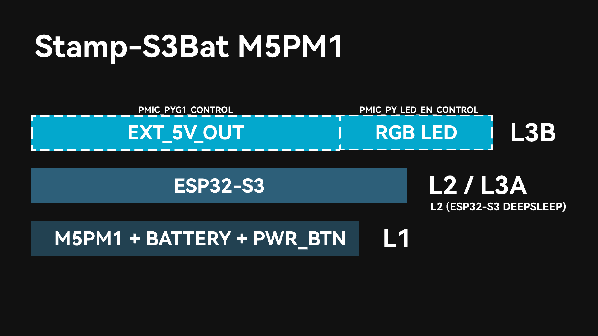
After the M5PM1 starts and powers up, L1, L2, and L3A will automatically turn on (DCDC3V3_EN_PP and CHG_EN_PP are on by default). At this point, the ESP32-S3 on the device completes initialization upon power-up, EXT_5V_OUT is not enabled, and the power supply for the RGB LED is not turned on.
L1
Under this power level, the battery maintains the power supply to the M5PM1. As long as the battery is not exhausted, this level of power will always be maintained. M5PM1 supports basic power on/off operations via buttons.
L2 / L3A
Under this power level, the power supply for the ESP32-S3 main controller is enabled. When the ESP32-S3 is in sleep mode, the power is at the L2 level. When the ESP32-S3 is in an active state, the power is at the L3A level.
The ESP32-S3 can shut down its own power supply (L2->L1/L0) by controlling the M5PM1 to enter sleep mode.
L3B
This power level can further enable the power supply for the EXT_5V_OUT output interface and the RGB LED through the M5PM1. Switch control can be achieved via the following APIs.
- Enable
EXT_5V_OUToutput: Controlled via PY_G1 (5VOUT_EN).
pm1.gpioSetFunc(M5PM1_GPIO_NUM_1, M5PM1_GPIO_FUNC_GPIO);
pm1.gpioSetMode(M5PM1_GPIO_NUM_1, M5PM1_GPIO_MODE_OUTPUT);
pm1.gpioSetDrive(M5PM1_GPIO_NUM_1, M5PM1_GPIO_DRIVE_PUSHPULL);
pm1.gpioSetOutput(M5PM1_GPIO_NUM_1, true);- Enable
RGB LEDpower supply: Controlled via PY_LED_EN.
pm1.setLedEnLevel(true)2. M5PM1 Sleep
Manual Sleep
The M5PM1 can be manually controlled via software to enter a sleep state to reduce the overall power consumption of the device. By default, directly setting sleep will revert the power to the L1 level. At this time, only the M5PM1 maintains power. In the absence of other wakeup sources, the PWR button must be clicked to wake it up.
External wakeup IOs or other wakeup sources (such as timers) can be configured before sleep. After the device enters the sleep state, the wakeup source can trigger the M5PM1 to wake up and restore power to the ESP32-S3.
pm1.shutdown();IO Wakeup
After starting this example program, the Stamp-S3Bat will configure G4 (WAKE) of the M5PM1 as the wakeup IO. After shutdown, pulling the WAKE pin low to create a falling edge will wake up the device.
#include <Arduino.h>
#include <M5PM1.h>
#include <Wire.h>

M5PM1 pm1;

static const uint8_t PIN_SDA = 48;
static const uint8_t PIN_SCL = 47;

void setup()
{
    Serial.begin(115200);
    delay(300);

    Wire.end();
    Wire.begin(PIN_SDA, PIN_SCL, 100000U);

    // Initialize PM1
    m5pm1_err_t err = pm1.begin(&Wire, M5PM1_DEFAULT_ADDR, PIN_SDA, PIN_SCL, M5PM1_I2C_FREQ_100K);

    if (err != M5PM1_OK) {
        Serial.printf("[PM1][E] PM1 initialization failed: %d\r\n", err);
        while (true) {
            delay(1000);
        }
    }
    Serial.printf("[PM1][I] PM1 initialization successful\r\n");

    pm1.irqClearGpioAll();
    pm1.irqClearSysAll();
    pm1.irqClearBtnAll();

    pm1.irqSetGpioMaskAll(M5PM1_IRQ_MASK_ENABLE);
    pm1.irqSetSysMaskAll(M5PM1_IRQ_MASK_ENABLE);
    pm1.irqSetBtnMaskAll(M5PM1_IRQ_MASK_ENABLE);

    pm1.irqSetGpioMask(M5PM1_IRQ_GPIO4, M5PM1_IRQ_MASK_DISABLE);
    pm1.gpioSetMode(M5PM1_GPIO_NUM_4, M5PM1_GPIO_MODE_INPUT);
    pm1.gpioSetPull(M5PM1_GPIO_NUM_4, M5PM1_GPIO_PULL_UP);

    // Configure G4 as IO wake source: low-level trigger (falling edge)
    m5pm1_err_t err_wake_en = pm1.gpioSetWakeEnable(M5PM1_GPIO_NUM_4, true);
    m5pm1_err_t err_wake_ed = pm1.gpioSetWakeEdge(M5PM1_GPIO_NUM_4, M5PM1_GPIO_WAKE_FALLING);
    if (err_wake_en != M5PM1_OK || err_wake_ed != M5PM1_OK) {
        Serial.printf("[PM1][E] GPIO wake config failed, en:%d edge:%d\r\n", err_wake_en, err_wake_ed);
        while (true) {
            delay(1000);
        }
    }
    Serial.printf("[PM1][I] Shutdown now, wait GPIO4 low level to wake\r\n");
    delay(1000);
    m5pm1_err_t err_shutdown = pm1.shutdown();
    if (err_shutdown != M5PM1_OK) {
        Serial.printf("[PM1][E] shutdown failed: %d\r\n", err_shutdown);
    }
}

void loop()
{
}Sleep Hold
In some special use cases, the M5PM1 is allowed to enter sleep to reduce power consumption while maintaining the current state of the chip's GPIO pins. To implement this function, the corresponding pin states must be configured before the M5PM1 enters sleep, and the GPIO state hold mechanism must be enabled.
- M5PM1 sleep while maintaining
M5PM1_GPIO_NUM_1(EXT_5V_OUT) power output.
pm1.gpioSetMode(M5PM1_GPIO_NUM_1, M5PM1_GPIO_MODE_OUTPUT);
pm1.gpioSetDrive(M5PM1_GPIO_NUM_1, M5PM1_GPIO_DRIVE_PUSHPULL);
pm1.gpioSetOutput(M5PM1_GPIO_NUM_1, true);
pm1.gpioSetPowerHold(M5PM1_GPIO_NUM_1, true);

Serial.println("[DEMO] GPIO1 HIGH + HOLD");
delay(1000);
Serial.println("[DEMO] Shutdown now");
delay(300);
pm1.shutdown();- M5PM1 sleep while maintaining
M5PM1_GPIO_NUM_4(WAKE) output at high level.
pm1.gpioSetMode(M5PM1_GPIO_NUM_4, M5PM1_GPIO_MODE_OUTPUT);
pm1.gpioSetDrive(M5PM1_GPIO_NUM_4, M5PM1_GPIO_DRIVE_PUSHPULL);
pm1.gpioSetOutput(M5PM1_GPIO_NUM_4, true);
pm1.gpioSetPowerHold(M5PM1_GPIO_NUM_4, true);

Serial.println("[DEMO] GPIO4 HIGH + HOLD");
delay(1000);
Serial.println("[DEMO] Shutdown now");
delay(300);
pm1.shutdown();I2C Idle Sleep
M5PM1 supports configuring an I2C idle communication automatic sleep state to reduce overall power consumption. After entering the sleep state, the first communication between the ESP32-S3 and the M5PM1 will be used to wake up the M5PM1; because this will result in communication failure, valid communication will occur on the next attempt after wakeup.
m5pm1_err_t setI2cSleepTime(uint8_t seconds);3. M5PM1 Timer
M5PM1 supports timer configuration. After the countdown ends, corresponding actions such as power on, power off, or reset can be executed.
m5pm1_err_t timerSet(uint32_t seconds, m5pm1_tim_action_t action);typedef enum {
M5PM1_TIM_ACTION_STOP = 0b000, // Stop, no action
M5PM1_TIM_ACTION_FLAG = 0b001, // Set flag only
M5PM1_TIM_ACTION_REBOOT = 0b010, // System reboot
M5PM1_TIM_ACTION_POWERON = 0b011, // Power on
M5PM1_TIM_ACTION_POWEROFF = 0b100 // Power off
} m5pm1_tim_action_t;Scheduled Power On/Off Example
After the device powers up and runs this program, it will automatically shut down after 10 seconds.
#include <M5Unified.h>
#include <M5PM1.h>
#include <Wire.h>

M5PM1 pm1;

void setup(void)
{
    M5.begin();
    Serial.begin(115200);

    auto sda = M5.getPin(m5::pin_name_t::in_i2c_sda);
    auto scl = M5.getPin(m5::pin_name_t::in_i2c_scl);

    Wire.end();
    Wire.begin(sda, scl, 100000U);

    if (pm1.begin(&Wire, M5PM1_DEFAULT_ADDR, sda, scl, M5PM1_I2C_FREQ_100K) != M5PM1_OK) {
        Serial.println("PM1 init failed");
        return;
    }

    Serial.println("Set timer: power off after 10s");
    pm1.timerSet(10, M5PM1_TIM_ACTION_POWEROFF);
}

void loop(void) {

}After the device executes this program, it will shut down immediately and automatically power on again after 10 seconds.
#include <M5Unified.h>
#include <M5PM1.h>
#include <Wire.h>

M5PM1 pm1;

void setup(void)
{
    M5.begin();
    Serial.begin(115200);

    auto sda = M5.getPin(m5::pin_name_t::in_i2c_sda);
    auto scl = M5.getPin(m5::pin_name_t::in_i2c_scl);

    Wire.end();
    Wire.begin(sda, scl, 100000U);

    if (pm1.begin(&Wire, M5PM1_DEFAULT_ADDR, sda, scl, M5PM1_I2C_FREQ_100K) != M5PM1_OK) {
        Serial.println("PM1 init failed");
        return;
    }

    Serial.println("Set timer: power on after 10s");
    pm1.timerSet(10, M5PM1_TIM_ACTION_POWERON);
    pm1.shutdown();  // Must enter shutdown first, then PM1 can wake it up by timer.
}

void loop(void) {

}4. RGB LED Control
#include <Arduino.h>
#include <M5PM1.h>
#include <Wire.h>

M5PM1 pm1;

#define PIN_SCL 47
#define PIN_SDA 48

static const uint8_t LED_COUNT  = 1;
static const uint8_t BRIGHTNESS = 64;

static const m5pm1_rgb_t COLOR_GREEN = {0, BRIGHTNESS, 0};

void setup()
{
    Serial.begin(115200);
    delay(2000);

    Wire.end();
    Wire.begin(PIN_SDA, PIN_SCL, 100000U);

    // Initialize PM1
    m5pm1_err_t err = pm1.begin(&Wire, M5PM1_DEFAULT_ADDR, PIN_SDA, PIN_SCL, M5PM1_I2C_FREQ_400K);

    if (err != M5PM1_OK) {
        Serial.printf("[PM1][E] PM1 initialization failed: %d\r\n", err);
        while (true) {
            delay(1000);
        }
    }
    Serial.printf("[PM1][I] PM1 initialization successful\r\n");

    // Configure PM1 GPIO0 for LED output path.
    pm1.gpioSetFunc(M5PM1_GPIO_NUM_0, M5PM1_GPIO_FUNC_OTHER);
    pm1.gpioSetDrive(M5PM1_GPIO_NUM_0, M5PM1_GPIO_DRIVE_PUSHPULL);
    pm1.gpioSetOutput(M5PM1_GPIO_NUM_0, true);
    pm1.pinMode(M5PM1_GPIO_NUM_0, M5PM1_OTHER);

    // Enable LED output and set LED count.
    m5pm1_err_t err1 = pm1.setLedEnLevel(true);
    if (err1 != M5PM1_OK) {
        Serial.printf("[PM1][E] Failed to enable LED output: %d\r\n", err1);
    }

    m5pm1_err_t err2 = pm1.setLedCount(LED_COUNT);
    if (err2 != M5PM1_OK) {
        Serial.printf("[PM1][E] Failed to set LED count: %d\r\n", err2);
    }

    // Keep LED solid green.
    m5pm1_err_t err3 = pm1.setLedColor(0, COLOR_GREEN);
    m5pm1_err_t err4 = pm1.refreshLeds();
    if (err3 != M5PM1_OK || err4 != M5PM1_OK) {
        Serial.printf("[PM1][E] Failed to set GREEN LED, color:%d refresh:%d\r\n", err3, err4);
    }
}

void loop()
{
    delay(1000);
}5. Charging Control
Switch the charging current of the charging IC to the battery via PY_G3_CHG_PROG (low level: 650mA / floating: 200mA).
Set the macro CHARGE_CURRENT_650MA_ENABLED to 1 to enable the 650mA high-current charging mode.
#include <Arduino.h>
#include <M5PM1.h>
#include <Wire.h>

M5PM1 pm1;

#define PIN_SCL 47
#define PIN_SDA 48
#define CHARGE_CURRENT_650MA_ENABLED 1
static const uint8_t LED_COUNT = 1;
static const uint8_t LED_BRIGHTNESS = 64;

static const m5pm1_gpio_num_t PY_G3_CHG_PROG = M5PM1_GPIO_NUM_3;

#if CHARGE_CURRENT_650MA_ENABLED
static const m5pm1_rgb_t LED_COLOR = {0, LED_BRIGHTNESS, 0};
#else
static const m5pm1_rgb_t LED_COLOR = {0, 0, LED_BRIGHTNESS};
#endif

static bool applyChargeCurrentConfig()
{
#if CHARGE_CURRENT_650MA_ENABLED
    return pm1.gpioSetMode(PY_G3_CHG_PROG, M5PM1_GPIO_MODE_OUTPUT) == M5PM1_OK &&
           pm1.gpioSetPull(PY_G3_CHG_PROG, M5PM1_GPIO_PULL_NONE) == M5PM1_OK &&
           pm1.gpioSetOutput(PY_G3_CHG_PROG, false) == M5PM1_OK;
#else
    return pm1.gpioSetMode(PY_G3_CHG_PROG, M5PM1_GPIO_MODE_INPUT) == M5PM1_OK &&
           pm1.gpioSetPull(PY_G3_CHG_PROG, M5PM1_GPIO_PULL_NONE) == M5PM1_OK;
#endif
}

static bool applyRgbLedConfig()
{
    bool ok = pm1.gpioSetFunc(M5PM1_GPIO_NUM_0, M5PM1_GPIO_FUNC_OTHER) == M5PM1_OK &&
              pm1.gpioSetDrive(M5PM1_GPIO_NUM_0, M5PM1_GPIO_DRIVE_PUSHPULL) == M5PM1_OK &&
              pm1.gpioSetOutput(M5PM1_GPIO_NUM_0, true) == M5PM1_OK;
    pm1.pinMode(M5PM1_GPIO_NUM_0, M5PM1_OTHER);
    return ok && pm1.setLedEnLevel(true) == M5PM1_OK && pm1.setLedCount(LED_COUNT) == M5PM1_OK &&
           pm1.setLedColor(0, LED_COLOR) == M5PM1_OK && pm1.refreshLeds() == M5PM1_OK;
}

void setup()
{
    delay(200);

    Wire.end();
    Wire.begin(PIN_SDA, PIN_SCL, 100000U);

    m5pm1_err_t err = pm1.begin(&Wire, M5PM1_DEFAULT_ADDR, PIN_SDA, PIN_SCL, M5PM1_I2C_FREQ_400K);

    pm1.setChargeEnable(true);

    if (err != M5PM1_OK) {
        while (true) {
            delay(1000);
        }
    }

    if (!applyChargeCurrentConfig()) {
        while (true) {
            delay(1000);
        }
    }

    if (!applyRgbLedConfig()) {
        while (true) {
            delay(1000);
        }
    }
}

void loop()
{
    delay(1000);
}6. Power Status
Read the current power status of the Stamp-S3Bat.
#include <Arduino.h>
#include <M5PM1.h>
#include <Wire.h>

M5PM1 pm1;

static const uint8_t PIN_SCL            = 47;
static const uint8_t PIN_SDA            = 48;
static const uint32_t PRINT_INTERVAL_MS = 2000;

static void printVoltages()
{
    uint16_t mv = 0;

    if (pm1.readVref(&mv) == M5PM1_OK) {
        Serial.printf("[PM1][I] Vref: %u mV (%.3f V)\r\n", mv, mv / 1000.0f);
    }
    if (pm1.readVbat(&mv) == M5PM1_OK) {
        Serial.printf("[PM1][I] VBAT: %u mV (%.3f V)\r\n", mv, mv / 1000.0f);
    }
    if (pm1.readVin(&mv) == M5PM1_OK) {
        Serial.printf("[PM1][I] VIN: %u mV (%.3f V)\r\n", mv, mv / 1000.0f);
    }
    if (pm1.read5VInOut(&mv) == M5PM1_OK) {
        Serial.printf("[PM1][I] 5V IN/OUT: %u mV (%.3f V)\r\n", mv, mv / 1000.0f);
    }
}

void setup()
{
    Serial.begin(115200);
    delay(300);
    Serial.println("[DEMO] Boot");

    Wire.end();
    Wire.begin(PIN_SDA, PIN_SCL, 100000U);
    if (pm1.begin(&Wire, M5PM1_DEFAULT_ADDR, PIN_SDA, PIN_SCL, M5PM1_I2C_FREQ_400K) != M5PM1_OK) {
        Serial.println("[DEMO] PM1 init failed");
        return;
    }
    Serial.println("[DEMO] PM1 init ok");
}

void loop()
{
    static uint32_t lastMs = 0;
    if (millis() - lastMs >= PRINT_INTERVAL_MS) {
        lastMs = millis();
        printVoltages();
    }
}