

Arduino入門
2. デバイス&サンプル
3. M5Unified
4. M5GFX
5. 拡張モジュール&サンプル
Unit
Module
Atomic
Tab5
IoT
アクセサリー
Module13.2 LoRa-1262 Arduino チュートリアル
1. 準備作業
- 環境設定: Arduino IDE 入門ガイドを参照して IDE をインストールし、使用する開発ボードに対応するボード管理と必要なドライバライブラリをインストールしてください。
- 使用するドライバライブラリ:
- 使用するハードウェア製品:


2. 注意事項
アンテナ接続
LoRa モジュールを使用する前に、適合する外部アンテナを接続してください。アンテナを接続せずに送信することは禁止されています。ハードウェアが恒久的に損傷するおそれがあります。
I2C アドレス
モジュールの IO エクスパンダーアドレスは、SW2 の A、B ディップスイッチで設定できます。アドレス表は以下のとおりです。
| A | B | I2C アドレス |
|---|---|---|
| 0 | 0 | 0x74 |
| 1 | 0 | 0x73 |
| 0 | 1 | 0x72 |
| 1 | 1 | 0x71 |
ピン互換性
ホストデバイスによってピン配置が異なるため、M5Stack が提供するピン互換性表を参照し、実際のピン接続に応じてサンプルプログラムを修正してください。
3. サンプルプログラム
- 本チュートリアルでは CoreS3 と Module13.2 LoRa-1262 を組み合わせて無線通信を行います。使用前に下図を参照し、ピンのディップスイッチを指定の位置に切り替えてください。
3.1 ピンディップスイッチ
- Module13.2 LoRa-1262 は SPI で通信します。実際の回路接続に応じて、プログラム内のピン定義を修正してください。CoreS3 に接続した場合、対応する SPI IO ピンは
G1 (NSS)、G2 (BUSY)、G37 (MOSI)、G35 (MISO)、G36 (SCK)、割り込み IO はG10 (IRQ)です。IO エクスパンダーのアドレスは、実物を下図で確認してください。

3.2 パラメータ設定
Module13.2 LoRa-1262 は複数のパラメータ設定に対応しています。使用前に以下の内容を参照して設定してください。各パラメータの意味や詳細についてはデータシートを参照し、用途に応じてサンプルプログラムのパラメータを調整してください。送信側と受信側のパラメータを一致させてください。
周波数 (LORA_FREQ)
- Module13.2 LoRa-1262 は
868 ~ 923 MHz帯域に対応しています。使用地域の電波法に従って周波数を選択してください。 - 送信側と受信側には同じ周波数を設定してください。
帯域幅 (LORA_BW)
- 単位は kHz です。帯域幅を小さくすると、一般に受信感度と長距離通信性能が向上しますが、データレートが低下し、パケット占有時間が長くなります。帯域幅を大きくするとデータレートは向上しますが、耐ノイズ性能と通信距離が低下する場合があります。
拡散率 (LORA_SF)
- 設定範囲は 6 ~ 12 です。
- 値を大きくすると、一般に受信感度と耐干渉性能が向上しますが、伝送速度が低下し、パケット占有時間が長くなります。
- 送信側と受信側には同じ拡散率を設定してください。
符号化率 (LORA_CR)
- 設定範囲は 5 ~ 8 で、それぞれ符号化率
4/5~4/8に対応します。 - 値を大きくすると誤り訂正能力は高くなりますが、有効データレートが低下し、パケット占有時間が長くなります。
同期ワード (LORA_SYNC_WORD)
- 異なる LoRa ネットワークを区別するために使用します。
- 同期ワードが一致した場合のみ、受信側はパケットを正しく識別できます。送信側と受信側には同じ同期ワードを設定してください。
送信出力 (LORA_TX_POWER)
- 設定範囲は -9 ~ 22 dBm です。
- 値を大きくすると、一般に送信出力と通信距離が増加しますが、消費電力と電源への要求も大きくなります。
注意:
1. 安定した電源を使用できない場合(例:CoreS3 バッテリーベースを使用する場合)は、低い出力値を設定してください。そうしないと、モジュールが正常に動作しない場合があります。
2. このパラメータは受信側には実質的な効果がなく、ソフトウェアを正常にコンパイルするためだけに使用されます。
2. このパラメータは受信側には実質的な効果がなく、ソフトウェアを正常にコンパイルするためだけに使用されます。
プリアンブル長 (LORA_PREAMBLE_LEN)
- プリアンブルは受信側がパケットの開始を検出するために使用します。長さを適切に増やすと弱い信号の受信に役立ちますが、パケット占有時間が長くなります。
- 送信側と受信側には同じ設定を使用してください。
注意
下記のコードでは
NSS、IRQ、BUSY の 3 本のピンのみを設定していますが、RadioLib ライブラリは使用するコントローラに応じて残りの SPI ピン (MOSI、MISO、SCK) を自動的に割り当てます。M5Unified ライブラリで初期化するとデバイスごとのデフォルトピンが使用されるため、手動で指定する必要はありません。3.3 送信側
cpp
1 2 3 4 5 6 7 8 9 10 11 12 13 14 15 16 17 18 19 20 21 22 23 24 25 26 27 28 29 30 31 32 33 34 35 36 37 38 39 40 41 42 43 44 45 46 47 48 49 50 51 52 53 54 55 56 57 58 59 60 61 62 63 64 65 66 67 68 69 70 71 72 73 74 75 76 77 78 79 80 81 82 83 84 85 86 87 88 89 90 91 92 93 94 95 96 97 98 99 100 101 102 103 104 105 106 107 108 109 110 111 112 113 114 115 116 117 118 119 120 121 122 123 124 125 126 127 128 129 130 131 132 133 134 135 136 137 138 139 140 141 142 143 144 145 146 147 148 149 150 151 152 153 154 155 156 157 158 159 160 161 162 163 164 165 166 167 168 169 170 171 172 173 174 175 176 177 178 179 180 181 182 183 184 185 186 187 188 189 190 191 192 193 194
#include <M5Unified.h>
#include <M5IOE1.h>
#include <RadioLib.h>

// M5IOE1 I2C address selected by SW2.
#define IO_EXPANDER_ADDRESS 0x74

// CoreS3 pins selected by the module DIP switches.
#define LORA_NSS_PIN  GPIO_NUM_1
#define LORA_BUSY_PIN GPIO_NUM_2
#define LORA_IRQ_PIN  GPIO_NUM_10

// M5IOE1 pins for LoRa reset, bypass, and power control.
#define PY_IO2_LORA_RST   M5IOE1_PIN_2
#define PY_IO3_BYPASS     M5IOE1_PIN_3
#define PY_IO5_PWR_EN     M5IOE1_PIN_5

// LoRa parameters. These values must match on both devices.
#define LORA_FREQ         868.0f  // Carrier frequency (MHz).
#define LORA_BW           125.0f  // Bandwidth (kHz).
#define LORA_SF           12      // Spreading factor.
#define LORA_CR           5       // Coding rate: 4/5.
#define LORA_SYNC_WORD    0x34    // Sync word.
#define LORA_TX_POWER     22      // TX power (dBm).
#define LORA_CURRENT_LIMIT 140.0f // TX current limit (mA).
#define LORA_PREAMBLE_LEN 20      // Preamble length (symbols).

// SX1262 pins: NSS, IRQ, reset (controlled by M5IOE1), and BUSY.
SX1262 radio = new Module(LORA_NSS_PIN, LORA_IRQ_PIN, RADIOLIB_NC, LORA_BUSY_PIN);
M5Canvas canvas(&M5.Lcd);
M5IOE1 ioe1;

int transmissionState = RADIOLIB_ERR_NONE;
volatile bool transmittedFlag = false;

bool setExpanderOutput(uint8_t pin, uint8_t level)
{
    // Configure one M5IOE1 pin as a push-pull output and set its level.
    m5ioe1_err_t error = M5IOE1_OK;
    ioe1.pinModeWithRes(pin, OUTPUT, &error);
    if (error != M5IOE1_OK) {
        return false;
    }
    if (ioe1.setDriveMode(pin, M5IOE1_DRIVE_PUSHPULL) != M5IOE1_OK) {
        return false;
    }
    ioe1.digitalWriteWithRes(pin, level, &error);
    return error == M5IOE1_OK;
}

bool initModuleControl()
{
    // Initialize the M5IOE1 control interface.
    const m5ioe1_err_t ioeState = ioe1.begin(
        &M5.In_I2C, IO_EXPANDER_ADDRESS, M5IOE1_I2C_FREQ_100K,
        M5IOE1_INT_MODE_DISABLED);
    if (ioeState != M5IOE1_OK) {
        Serial.printf("M5IOE1 init failed at 0x%02X, code: %d\n",
                      IO_EXPANDER_ADDRESS, ioeState);
        return false;
    }

    // Hold reset, set the bypass control, and disable module power.
    if (!setExpanderOutput(PY_IO2_LORA_RST, LOW) ||
        !setExpanderOutput(PY_IO3_BYPASS, HIGH) ||
        !setExpanderOutput(PY_IO5_PWR_EN, LOW)) {
        return false;
    }
    delay(25);

    // Enable module power before releasing reset.
    if (!setExpanderOutput(PY_IO5_PWR_EN, HIGH)) {
        return false;
    }
    delay(120);

    // Release reset after the power rail is stable.
    if (!setExpanderOutput(PY_IO2_LORA_RST, HIGH)) {
        return false;
    }
    delay(120);
    return true;
}

void IRAM_ATTR setFlag(void)
{
    // Mark the packet-sent event for loop().
    transmittedFlag = true;
}

void showSending(const String& payload, int count)
{
    canvas.clear();
    canvas.setCursor(0, 5);
    canvas.printf("[SX1262]\nSending #%d packet......\n", count);
    canvas.printf("Data:\n %s\n", payload.c_str());
    canvas.pushSprite(0, 0);
}

void setup()
{
    auto cfg = M5.config();
    M5.begin(cfg);
    Serial.begin(115200);
    canvas.createSprite(320, 240);
    canvas.setFont(&fonts::FreeMonoBold9pt7b);

    if (!initModuleControl()) {
        Serial.println(F("IO_EXP init failed"));
        canvas.println(F("IO_EXP init failed"));
        canvas.pushSprite(0, 0);
        while (true) {
            delay(1000);
        }
    }

    // Initialize the SX1262.
    Serial.print(F("[SX1262] Initializing ... "));
    int state = radio.begin(LORA_FREQ, LORA_BW, LORA_SF, LORA_CR,
                            LORA_SYNC_WORD, LORA_TX_POWER, LORA_PREAMBLE_LEN,
                            3.0f, true);
    if (state != RADIOLIB_ERR_NONE) {
        Serial.print(F("failed, code "));
        Serial.println(state);
        canvas.println(F("SX1262 init failed"));
        canvas.pushSprite(0, 0);
        while (true) {
            delay(1000);
        }
    }
    state = radio.setCurrentLimit(LORA_CURRENT_LIMIT);
    if (state != RADIOLIB_ERR_NONE) {
        Serial.print(F("current limit setup failed, code "));
        Serial.println(state);
        canvas.println(F("Current limit setup failed"));
        canvas.pushSprite(0, 0);
        while (true) {
            delay(1000);
        }
    }
    Serial.println(F("success!"));

    // Register the callback for the packet-sent interrupt.
    radio.setPacketSentAction(setFlag);
    // Send an initial packet to start interrupt-driven transmission.
    Serial.print(F("[SX1262] Sending first packet ... "));
    transmissionState = radio.startTransmit("Transmitter Ready");
    if (transmissionState != RADIOLIB_ERR_NONE) {
        Serial.print(F("startTransmit failed, code: "));
        Serial.println(transmissionState);
    }
    canvas.clear();
    canvas.setCursor(0, 5);
    canvas.println(F("[SX1262]"));
    canvas.println(F("Transmitter Ready"));
    canvas.pushSprite(0, 0);
}

int count = 0;

void loop()
{
    // Wait until the packet-sent interrupt is received.
    if (!transmittedFlag) {
        return;
    }
    transmittedFlag = false;

    if (transmissionState == RADIOLIB_ERR_NONE) {
        Serial.println(F("Transmission finished!"));
        canvas.println(F("Send successfully!"));
        canvas.pushSprite(0, 0);
    } else {
        Serial.print(F("Send failed, code: "));
        Serial.println(transmissionState);
        canvas.println(F("Send failed"));
        canvas.printf("code: %d\n", transmissionState);
        canvas.pushSprite(0, 0);
    }

    // Finish the previous transmission before starting the next one.
    radio.finishTransmit();
    delay(1000);

    // Start the next packet.
    String payload = "Module13.2 LoRa-1262 #" + String(count);
    Serial.printf("[SX1262] Sending #%d packet ... ", count);
    transmissionState = radio.startTransmit(payload);
    if (transmissionState != RADIOLIB_ERR_NONE) {
        Serial.print(F("startTransmit failed, code: "));
        Serial.println(transmissionState);
    }
    showSending(payload, count++);
}3.4 受信側
cpp
1 2 3 4 5 6 7 8 9 10 11 12 13 14 15 16 17 18 19 20 21 22 23 24 25 26 27 28 29 30 31 32 33 34 35 36 37 38 39 40 41 42 43 44 45 46 47 48 49 50 51 52 53 54 55 56 57 58 59 60 61 62 63 64 65 66 67 68 69 70 71 72 73 74 75 76 77 78 79 80 81 82 83 84 85 86 87 88 89 90 91 92 93 94 95 96 97 98 99 100 101 102 103 104 105 106 107 108 109 110 111 112 113 114 115 116 117 118 119 120 121 122 123 124 125 126 127 128 129 130 131 132 133 134 135 136 137 138 139 140 141 142 143 144 145 146 147 148 149 150 151 152 153 154 155 156 157 158 159 160 161 162 163 164 165 166 167 168 169 170 171 172 173 174 175 176 177 178 179 180 181 182 183 184 185 186 187 188 189 190 191 192 193 194 195 196 197 198 199 200 201 202 203 204
#include <M5Unified.h>
#include <M5IOE1.h>
#include <RadioLib.h>

// M5IOE1 I2C address selected by SW2.
#define IO_EXPANDER_ADDRESS 0x74

// CoreS3 pins selected by the module DIP switches.
#define LORA_NSS_PIN  GPIO_NUM_1
#define LORA_BUSY_PIN GPIO_NUM_2
#define LORA_IRQ_PIN  GPIO_NUM_10

// M5IOE1 pins for LoRa reset, bypass, and power control.
#define PY_IO2_LORA_RST   M5IOE1_PIN_2
#define PY_IO3_BYPASS     M5IOE1_PIN_3
#define PY_IO5_PWR_EN     M5IOE1_PIN_5

// LoRa parameters. These values must match on both devices.
#define LORA_FREQ         868.0f  // Carrier frequency (MHz).
#define LORA_BW           125.0f  // Bandwidth (kHz).
#define LORA_SF           12      // Spreading factor.
#define LORA_CR           5       // Coding rate: 4/5.
#define LORA_SYNC_WORD    0x34    // Sync word.
#define LORA_TX_POWER     22      // TX power (dBm).
#define LORA_CURRENT_LIMIT 140.0f // TX current limit (mA).
#define LORA_PREAMBLE_LEN 20      // Preamble length (symbols).

// SX1262 pins: NSS, IRQ, reset (controlled by M5IOE1), and BUSY.
SX1262 radio = new Module(LORA_NSS_PIN, LORA_IRQ_PIN, RADIOLIB_NC, LORA_BUSY_PIN);
M5Canvas canvas(&M5.Lcd);
M5IOE1 ioe1;

// Set by the packet-received interrupt.
volatile bool receivedFlag = false;

bool setExpanderOutput(uint8_t pin, uint8_t level)
{
    // Configure one M5IOE1 pin as a push-pull output and set its level.
    m5ioe1_err_t error = M5IOE1_OK;
    ioe1.pinModeWithRes(pin, OUTPUT, &error);
    if (error != M5IOE1_OK) {
        return false;
    }
    if (ioe1.setDriveMode(pin, M5IOE1_DRIVE_PUSHPULL) != M5IOE1_OK) {
        return false;
    }
    ioe1.digitalWriteWithRes(pin, level, &error);
    return error == M5IOE1_OK;
}

bool initModuleControl()
{
    // Initialize the M5IOE1 control interface.
    const m5ioe1_err_t ioeState = ioe1.begin(
        &M5.In_I2C, IO_EXPANDER_ADDRESS, M5IOE1_I2C_FREQ_100K,
        M5IOE1_INT_MODE_DISABLED);
    if (ioeState != M5IOE1_OK) {
        Serial.printf("M5IOE1 init failed at 0x%02X, code: %d\n",
                      IO_EXPANDER_ADDRESS, ioeState);
        return false;
    }

    // Hold reset, set the bypass control, and disable module power.
    if (!setExpanderOutput(PY_IO2_LORA_RST, LOW) ||
        !setExpanderOutput(PY_IO3_BYPASS, HIGH) ||
        !setExpanderOutput(PY_IO5_PWR_EN, LOW)) {
        return false;
    }
    delay(25);

    // Enable module power before releasing reset.
    if (!setExpanderOutput(PY_IO5_PWR_EN, HIGH)) {
        return false;
    }
    delay(120);

    // Release reset after the power rail is stable.
    if (!setExpanderOutput(PY_IO2_LORA_RST, HIGH)) {
        return false;
    }
    delay(120);
    return true;
}

void IRAM_ATTR setFlag(void)
{
    // Mark the packet-received event for loop().
    receivedFlag = true;
}

void setup()
{
    auto cfg = M5.config();
    M5.begin(cfg);
    Serial.begin(115200);
    canvas.createSprite(320, 240);
    canvas.setFont(&fonts::FreeMonoBold9pt7b);

    if (!initModuleControl()) {
        Serial.println(F("IO_EXP init failed"));
        canvas.println(F("IO_EXP init failed"));
        canvas.pushSprite(0, 0);
        while (true) {
            delay(1000);
        }
    }

    // Initialize the SX1262.
    Serial.print(F("[SX1262] Initializing ... "));
    int state = radio.begin(LORA_FREQ, LORA_BW, LORA_SF, LORA_CR,
                            LORA_SYNC_WORD, LORA_TX_POWER, LORA_PREAMBLE_LEN,
                            3.0f, true);
    if (state != RADIOLIB_ERR_NONE) {
        Serial.print(F("failed, code "));
        Serial.println(state);
        canvas.println(F("SX1262 init failed"));
        canvas.pushSprite(0, 0);
        while (true) {
            delay(1000);
        }
    }
    state = radio.setCurrentLimit(LORA_CURRENT_LIMIT);
    if (state != RADIOLIB_ERR_NONE) {
        Serial.print(F("current limit setup failed, code "));
        Serial.println(state);
        canvas.println(F("Current limit setup failed"));
        canvas.pushSprite(0, 0);
        while (true) {
            delay(1000);
        }
    }
    Serial.println(F("success!"));

    // Register the callback for the packet-received interrupt.
    radio.setPacketReceivedAction(setFlag);
    // Start interrupt-driven receive mode.
    Serial.print(F("[SX1262] Starting to listen ... "));
    state = radio.startReceive();
    if (state != RADIOLIB_ERR_NONE) {
        Serial.print(F("failed, code "));
        Serial.println(state);
        canvas.println(F("Receive start failed"));
        canvas.pushSprite(0, 0);
        while (true) {
            delay(1000);
        }
    }
    Serial.println(F("success!"));

    canvas.setCursor(0, 5);
    canvas.println(F("[SX1262]"));
    canvas.println(F("Waiting for packet..."));
    canvas.pushSprite(0, 0);
}

void loop()
{
    // Wait until the packet-received interrupt is received.
    if (!receivedFlag) {
        return;
    }
    receivedFlag = false;

    // Read the packet after the interrupt is received.
    String payload;
    int state = radio.readData(payload);
    if (state == RADIOLIB_ERR_NONE) {
        // Read link quality information for the received packet.
        const float rssi = radio.getRSSI();
        const float snr = radio.getSNR();
        const float frequencyError = radio.getFrequencyError();

        Serial.println(F("[SX1262] Received packet:"));
        Serial.print(F("[SX1262] Data:\t\t"));
        Serial.println(payload);
        Serial.print(F("[SX1262] RSSI:\t\t"));
        Serial.print(rssi);
        Serial.println(F(" dBm"));
        Serial.print(F("[SX1262] SNR:\t\t"));
        Serial.print(snr);
        Serial.println(F(" dB"));
        Serial.print(F("[SX1262] Frequency error:\t"));
        Serial.print(frequencyError);
        Serial.println(F(" Hz"));

        canvas.clear();
        canvas.setCursor(0, 5);
        canvas.printf("[SX1262]\nReceived packet:\n");
        canvas.printf("Data:\n %s\n", payload.c_str());
        canvas.printf("RSSI: %0.2f dBm\n", rssi);
        canvas.printf("SNR: %0.2f dB\n", snr);
        canvas.printf("Freq err: %0.2f Hz\n", frequencyError);
        canvas.pushSprite(0, 0);
    } else if (state == RADIOLIB_ERR_CRC_MISMATCH) {
        Serial.println(F("[SX1262] CRC error!"));
    } else {
        Serial.print(F("[SX1262] Receive failed, code: "));
        Serial.println(state);
    }

    // Return to continuous receive mode.
    radio.finishReceive();
    radio.startReceive();
}4. コンパイルとアップロード
- 1. ダウンロードモードに入る:CoreS3 のリセットボタンを約 2 秒間長押しし、内蔵の緑色 LED が点灯したらボタンを離します。ボタンを離すと緑色 LED が消灯し、デバイスがダウンロードモードに入り、書き込み待機状態になったことを示します。
説明
デバイスによって、プログラムを書き込む前にダウンロードモードへ入る必要があります。手順はメインコントローラによって異なる場合があります。詳細は、Arduino IDE 入門ガイドページ下部のデバイス別プログラム書き込みチュートリアル一覧を参照してください。
.gif)
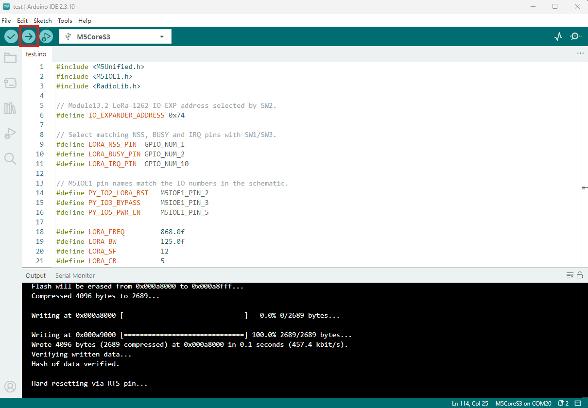
- 2. デバイスポートを選択し、Arduino IDE の左上にあるコンパイルとアップロードボタンをクリックします。プログラムのコンパイルとデバイスへの書き込みが完了するまで待ちます。
5. 情報送受信の動作例
送信側はカウンターを含む文字列を毎秒送信します。受信側は受信した文字列を出力し、RSSI などの情報を表示します。

- 送信側のシリアル出力:
[SX1262] Sending #34 packet ... Transmission finished!- 受信側のシリアル出力:
[SX1262] Received packet:
[SX1262] Data:           Module13.2 LoRa-1262 #34
[SX1262] RSSI:           -0.00 dBm
[SX1262] SNR:            5.00 dB
[SX1262] Frequency error: 23.01 HzPage Tools