

Arduino入門
2. デバイス&サンプル
3. M5Unified
4. M5GFX
5. 拡張モジュール&サンプル
Unit
Module
Atomic
Tab5
IoT
アクセサリー
Module13.2 Servo2 Arduino 使用手順
1. 準備作業
環境設定:Arduino IDE 入門チュートリアルを参照して IDE をインストールし、使用する開発ボードに対応するボードパッケージと必要なドライバライブラリをインストールしてください。
使用するドライバライブラリ:
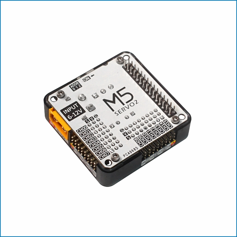
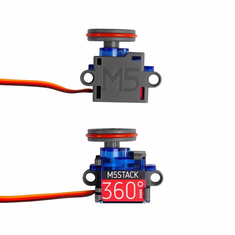
使用するハードウェア製品:

2. 注意事項
ピン互換性
ホストデバイスごとにピン構成が異なるため、使用前に製品ドキュメントのピン互換性表を参照し、実際のピン接続に応じてサンプルプログラムを修正してください。
3. サンプルプログラム
- このチュートリアルでは、CoreS3 と Module13.2 Servo2 を組み合わせてサーボを制御します。Module13.2 Servo2 は I2C で通信します。実際の回路接続に応じて、プログラム内のピン定義を変更してください。デバイス接続後、対応する I2C IO ピンは
G12 (SDA)とG11 (SCL)です。
3.1 マルチチャネル制御
cpp
1 2 3 4 5 6 7 8 9 10 11 12 13 14 15 16 17 18 19 20 21 22 23 24 25 26 27 28 29 30 31 32 33 34 35 36 37 38 39 40 41 42 43 44 45 46 47 48 49 50 51 52 53 54 55 56 57 58 59 60 61 62 63 64 65 66 67 68 69 70 71 72 73 74 75 76 77 78 79 80 81 82 83 84 85 86 87 88 89 90 91 92 93 94 95
#include <M5Unified.h>
#include <Wire.h>
#include "Adafruit_PWMServoDriver.h"

#define SERVO_FREQ 50  // Servo PWM frequency.
#define SERVO2_I2C_ADDRESS 0x41

Adafruit_PWMServoDriver* pwm = nullptr;

void setup()
{
    auto cfg = M5.config();
    M5.begin(cfg);
    M5.Lcd.setFont(&fonts::FreeMonoBold12pt7b);
    Serial.begin(115200);

    // Get M5Bus I2C pins.
    const int8_t wireSda = M5.getPin(m5::pin_name_t::in_i2c_sda);
    const int8_t wireScl = M5.getPin(m5::pin_name_t::in_i2c_scl);

    // Find the configured SERVO2 address.
    Serial.printf("Scanning SERVO2 address 0x%02X...\n", SERVO2_I2C_ADDRESS);
    if (M5.In_I2C.scanID(SERVO2_I2C_ADDRESS)) {
        Serial.printf("Found PCA9685 at 0x%02X\n", SERVO2_I2C_ADDRESS);
    } else {
        Serial.println("PCA9685 not found on M5Bus");
        M5.Display.drawString("PCA9685 not found", 10, 80);
        while (true) {
            delay(1000);
        }
    }

    Wire.setPins(wireSda, wireScl);
    pwm = new Adafruit_PWMServoDriver(SERVO2_I2C_ADDRESS, Wire);

    if (!pwm->begin()) {
        Serial.printf("Wire could not initialize PCA9685 at 0x%02X\n", SERVO2_I2C_ADDRESS);
        M5.Display.drawString("Wire init failed", 10, 80);
        while (true) {
            delay(1000);
        }
    }

    // Set the PWM frequency for analog servos.
    pwm->setPWMFreq(SERVO_FREQ);

    M5.Lcd.setTextColor(TFT_GREEN, TFT_BLACK);
    M5.Lcd.drawCenterString("Module13.2 Servo2 Test", 160, 10);
}

// Set one PCA9685 channel using a pulse width in milliseconds.
void setServoPulse(uint8_t n, double pulse)
{
    double pulselength;

    // Calculate the PWM period in microseconds.
    pulselength = 1000000;
    pulselength /= SERVO_FREQ;

    // Print the period for debugging.
    Serial.print(pulselength);
    Serial.println(" us per period");

    // Convert the period to one 12-bit PWM step.
    pulselength /= 4096;
    Serial.print(pulselength);
    Serial.println(" us per bit");

    // Convert the pulse width from milliseconds to PWM steps.
    pulse *= 1000;
    pulse /= pulselength;
    Serial.println(pulse);

    // Output the requested high pulse.
    pwm->setPWM(n, 0, pulse);
}

void loop()
{
    // Drive all channels with a 0.5 ms pulse.
    for (int i = 0; i < 16; i++) {
        setServoPulse(i, 0.5);
    }
    M5.Lcd.fillRect(0, 70, 320, 20, TFT_BLACK);
    M5.Lcd.drawCenterString("Pulse width: 0.5 ms", 160, 80);
    delay(1000);

    // Drive all channels with a 2.5 ms pulse.
    for (int i = 0; i < 16; i++) {
        setServoPulse(i, 2.5);
    }
    M5.Lcd.fillRect(0, 70, 320, 20, TFT_BLACK);
    M5.Lcd.drawCenterString("Pulse width: 2.5 ms", 160, 80);
    delay(1000);
}3.2 ALL_CALL 機能の設定
I2C アドレスの競合
Module13.2 Servo2 に搭載された PCA9685 チップは、複数のチップを同期制御するための ALL_CALL ブロードキャストアドレス
0x70 がデフォルトで有効になっています。電源投入後、モジュールは自身の I2C 通信アドレス (0x40 ~ 0x47) へのリクエストだけでなく、ALL_CALL 機能の I2C アドレス 0x70 にも応答します。現在の I2C バスに同じアドレスのデバイスが接続されている場合、アドレスが競合し、通信異常が発生する可能性があります。PCA9685 の MODE1 レジスタ (0x00H) の ALLCALL (bit:0) を 0 に設定して ALL_CALL 機能を無効にすることで、この問題を解決できます。cpp
1 2 3 4 5 6 7 8 9 10 11 12 13 14 15 16 17 18 19 20 21 22 23 24 25 26 27 28 29 30 31 32 33 34 35 36 37 38 39 40 41 42 43 44 45 46 47 48 49 50 51 52 53 54 55 56 57 58 59 60 61 62 63 64 65 66 67 68 69 70 71 72 73 74 75 76 77 78 79 80 81 82 83 84 85 86 87 88 89 90 91 92 93 94 95 96 97 98 99 100 101 102 103 104 105 106 107 108 109 110 111 112 113 114 115 116 117 118 119
#include <M5Unified.h>
#include <Wire.h>

#define SERVO2_I2C_ADDRESS 0x41

constexpr uint8_t PCA9685_MODE1_REG = 0x00;
constexpr uint8_t PCA9685_ALLCALL_BIT = 0x01;

bool readRegister8(uint8_t address, uint8_t reg, uint8_t &value)
{
    Wire.beginTransmission(address);
    Wire.write(reg);

    if (Wire.endTransmission(false) != 0) {
        return false;
    }

    if (Wire.requestFrom(address, static_cast<uint8_t>(1)) != 1) {
        return false;
    }

    value = Wire.read();
    return true;
}

bool writeRegister8(uint8_t address, uint8_t reg, uint8_t value)
{
    Wire.beginTransmission(address);
    Wire.write(reg);
    Wire.write(value);
    return Wire.endTransmission(true) == 0;
}

bool setAllCall(uint8_t address, bool enable)
{
    uint8_t mode1 = 0;

    if (!readRegister8(address, PCA9685_MODE1_REG, mode1)) {
        return false;
    }

    // Set or clear MODE1 bit 0 and preserve the other MODE1 bits.
    if (enable) {
        mode1 |= PCA9685_ALLCALL_BIT;
    } else {
        mode1 &= static_cast<uint8_t>(~PCA9685_ALLCALL_BIT);
    }
    return writeRegister8(address, PCA9685_MODE1_REG, mode1);
}

bool probeI2C(uint8_t address)
{
    Wire.beginTransmission(address);
    return Wire.endTransmission(true) == 0;
}

void setup()
{
    auto cfg = M5.config();
    M5.begin(cfg);

    Serial.begin(115200);
    delay(500);

    const int8_t wireSda = M5.getPin(m5::pin_name_t::in_i2c_sda);
    const int8_t wireScl = M5.getPin(m5::pin_name_t::in_i2c_scl);
    Wire.setPins(wireSda, wireScl);
    Wire.begin();

    if (!probeI2C(SERVO2_I2C_ADDRESS)) {
        Serial.printf("PCA9685 not found at 0x%02X\n", SERVO2_I2C_ADDRESS);
        while (true) {
            delay(1000);
        }
    }

    // Enable ALL_CALL and test the 0x70 address.
    if (setAllCall(SERVO2_I2C_ADDRESS, true)) {
        uint8_t mode1 = 0;
        if (readRegister8(SERVO2_I2C_ADDRESS, PCA9685_MODE1_REG, mode1)) {
            Serial.printf("ALL_CALL enabled, MODE1: 0x%02X\n", mode1);
        } else {
            Serial.println("ALL_CALL enabled, but MODE1 readback failed");
        }
    } else {
        Serial.println("Failed to enable ALL_CALL");
    }

    Serial.println("Test 0x70 with ALL_CALL enabled:");
    if (probeI2C(0x70)) {
        Serial.println("0x70: ACK");
    } else {
        Serial.println("0x70: NACK");
    }

    // Disable ALL_CALL and test the 0x70 address again.
    if (setAllCall(SERVO2_I2C_ADDRESS, false)) {
        uint8_t mode1 = 0;
        if (readRegister8(SERVO2_I2C_ADDRESS, PCA9685_MODE1_REG, mode1)) {
            Serial.printf("ALL_CALL disabled, MODE1: 0x%02X\n", mode1);
        } else {
            Serial.println("ALL_CALL disabled, but MODE1 readback failed");
        }
    } else {
        Serial.println("Failed to disable ALL_CALL");
    }

    Serial.println("Test 0x70 with ALL_CALL disabled:");
    if (probeI2C(0x70)) {
        Serial.println("0x70: ACK");
    } else {
        Serial.println("0x70: NACK");
    }
}

void loop()
{
    delay(1000);
}シリアル出力例:
ALL_CALL disabled
MODE1: 0x20
0x70: NACK
ALL_CALL enabled, MODE1: 0x21
Test 0x70 with ALL_CALL enabled:
0x70: ACK
ALL_CALL disabled, MODE1: 0x20
Test 0x70 with ALL_CALL disabled:
0x70: NACK4. コンパイルとアップロード
- 1. ダウンロードモードに入る:CoreS3 のリセットボタンを長押し(約 2 秒)し、内部の緑色 LED が点灯したら離します。これでデバイスはダウンロードモードに入り、書き込み待機状態になります。 ボタンを離すと緑色 LEDが消灯し、デバイスがダウンロードモードに入ったことを確認できます。
説明
デバイスによって、プログラムを書き込む前にダウンロードモードに入る必要があります。手順はメインコントローラーによって異なる場合があります。詳細は、Arduino IDE 入門チュートリアルページ下部のデバイス別プログラム書き込みチュートリアル一覧を参照してください。
.gif)
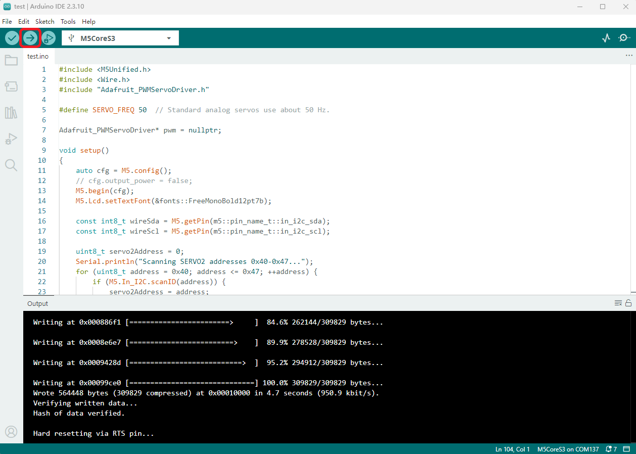
- 2. デバイスのポートを選択し、Arduino IDE 左上のコンパイル&アップロードボタンをクリックします。プログラムのコンパイルとデバイスへのアップロードが完了するまで待ちます。
5. サーボ駆動
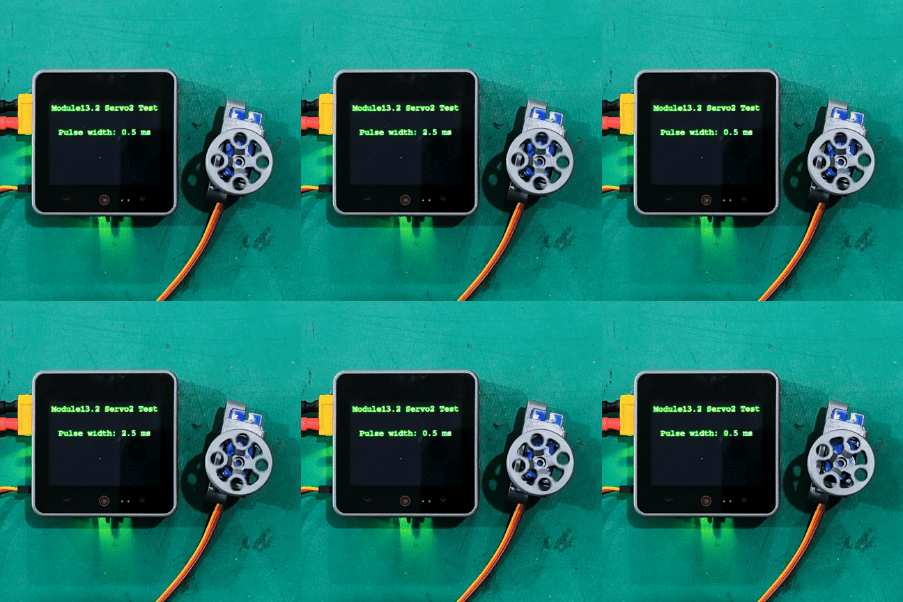
- 電源を投入すると Module13.2 Servo2 モジュールが自動的に初期化され、その後 0.5ms / 2.5ms のパルス幅を繰り返し設定してサーボを駆動します。
説明
サンプルコードでは実際に 16 チャンネルすべてを駆動しますが、下の画像ではデモ用に 1 チャンネルだけサーボを接続しています。
Page Tools