

Arduino 上手教程
2. 设备开发 & 案例程序
3. M5Unified
4. M5GFX
5. 扩展模块
Unit
Module
Atomic
Tab5
IoT
Module13.2 Servo2 Arduino 使用教程
1. 准备工作
环境配置: 参考 Arduino IDE 上手教程完成 IDE 安装,并根据实际使用的开发板安装对应的板管理,与需要的驱动库。
使用到的驱动库:
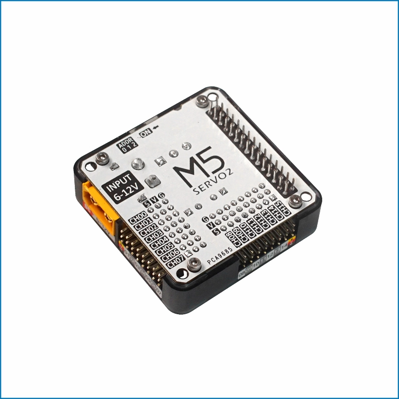
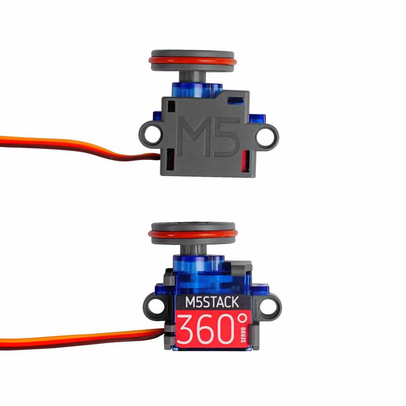
使用到的硬件产品:

2. 注意事项
引脚兼容性
由于每款主机的引脚配置不同,使用前请参考产品文档中的引脚兼容表,并根据实际引脚连接情况修改案例程序。
3. 案例程序
- 本教程中使用的主控设备为 CoreS3,搭配 Module13.2 Servo2 实现舵机控制。Module13.2 Servo2 使用 I2C 通讯,请根据实际的电路连接修改程序中的引脚定义,设备连接后对应的 I2C IO 为
G12 (SDA)、G11 (SCL)。
3.1 多通道控制
cpp
1 2 3 4 5 6 7 8 9 10 11 12 13 14 15 16 17 18 19 20 21 22 23 24 25 26 27 28 29 30 31 32 33 34 35 36 37 38 39 40 41 42 43 44 45 46 47 48 49 50 51 52 53 54 55 56 57 58 59 60 61 62 63 64 65 66 67 68 69 70 71 72 73 74 75 76 77 78 79 80 81 82 83 84 85 86 87 88 89 90 91 92 93 94 95
#include <M5Unified.h>
#include <Wire.h>
#include "Adafruit_PWMServoDriver.h"

#define SERVO_FREQ 50  // Servo PWM frequency.
#define SERVO2_I2C_ADDRESS 0x41

Adafruit_PWMServoDriver* pwm = nullptr;

void setup()
{
    auto cfg = M5.config();
    M5.begin(cfg);
    M5.Lcd.setFont(&fonts::FreeMonoBold12pt7b);
    Serial.begin(115200);

    // Get M5Bus I2C pins.
    const int8_t wireSda = M5.getPin(m5::pin_name_t::in_i2c_sda);
    const int8_t wireScl = M5.getPin(m5::pin_name_t::in_i2c_scl);

    // Find the configured SERVO2 address.
    Serial.printf("Scanning SERVO2 address 0x%02X...\n", SERVO2_I2C_ADDRESS);
    if (M5.In_I2C.scanID(SERVO2_I2C_ADDRESS)) {
        Serial.printf("Found PCA9685 at 0x%02X\n", SERVO2_I2C_ADDRESS);
    } else {
        Serial.println("PCA9685 not found on M5Bus");
        M5.Display.drawString("PCA9685 not found", 10, 80);
        while (true) {
            delay(1000);
        }
    }

    Wire.setPins(wireSda, wireScl);
    pwm = new Adafruit_PWMServoDriver(SERVO2_I2C_ADDRESS, Wire);

    if (!pwm->begin()) {
        Serial.printf("Wire could not initialize PCA9685 at 0x%02X\n", SERVO2_I2C_ADDRESS);
        M5.Display.drawString("Wire init failed", 10, 80);
        while (true) {
            delay(1000);
        }
    }

    // Set the PWM frequency for analog servos.
    pwm->setPWMFreq(SERVO_FREQ);

    M5.Lcd.setTextColor(TFT_GREEN, TFT_BLACK);
    M5.Lcd.drawCenterString("Module13.2 Servo2 Test", 160, 10);
}

// Set one PCA9685 channel using a pulse width in milliseconds.
void setServoPulse(uint8_t n, double pulse)
{
    double pulselength;

    // Calculate the PWM period in microseconds.
    pulselength = 1000000;
    pulselength /= SERVO_FREQ;

    // Print the period for debugging.
    Serial.print(pulselength);
    Serial.println(" us per period");

    // Convert the period to one 12-bit PWM step.
    pulselength /= 4096;
    Serial.print(pulselength);
    Serial.println(" us per bit");

    // Convert the pulse width from milliseconds to PWM steps.
    pulse *= 1000;
    pulse /= pulselength;
    Serial.println(pulse);

    // Output the requested high pulse.
    pwm->setPWM(n, 0, pulse);
}

void loop()
{
    // Drive all channels with a 0.5 ms pulse.
    for (int i = 0; i < 16; i++) {
        setServoPulse(i, 0.5);
    }
    M5.Lcd.fillRect(0, 70, 320, 20, TFT_BLACK);
    M5.Lcd.drawCenterString("Pulse width: 0.5 ms", 160, 80);
    delay(1000);

    // Drive all channels with a 2.5 ms pulse.
    for (int i = 0; i < 16; i++) {
        setServoPulse(i, 2.5);
    }
    M5.Lcd.fillRect(0, 70, 320, 20, TFT_BLACK);
    M5.Lcd.drawCenterString("Pulse width: 2.5 ms", 160, 80);
    delay(1000);
}3.2 ALL_CALL 功能配置
I2C 地址冲突
Module13.2 Servo2 内置
PCA9685 芯片默认使能 ALL_CALL 广播地址0x70,用于多个芯片同步控制。模块上电后,除接收本机的 I2C 通信地址 (0x40 ~ 0x47) 的请求以外,还会额外响应 ALL_CALL 功能的 I2C 地址 0x70。如果当前 I2C 总线上连接了相同地址的设备,将引发地址冲突,导致通信异常。该情况可通过配置 PCA9685 的工作模式寄存器 (0x00H) 中的 ALLCALL (bit:0),将其设置为 0 即可禁用ALL_CALL功能。cpp
1 2 3 4 5 6 7 8 9 10 11 12 13 14 15 16 17 18 19 20 21 22 23 24 25 26 27 28 29 30 31 32 33 34 35 36 37 38 39 40 41 42 43 44 45 46 47 48 49 50 51 52 53 54 55 56 57 58 59 60 61 62 63 64 65 66 67 68 69 70 71 72 73 74 75 76 77 78 79 80 81 82 83 84 85 86 87 88 89 90 91 92 93 94 95 96 97 98 99 100 101 102 103 104 105 106 107 108 109 110 111 112 113 114 115 116 117 118 119
#include <M5Unified.h>
#include <Wire.h>

#define SERVO2_I2C_ADDRESS 0x41

constexpr uint8_t PCA9685_MODE1_REG = 0x00;
constexpr uint8_t PCA9685_ALLCALL_BIT = 0x01;

bool readRegister8(uint8_t address, uint8_t reg, uint8_t &value)
{
    Wire.beginTransmission(address);
    Wire.write(reg);

    if (Wire.endTransmission(false) != 0) {
        return false;
    }

    if (Wire.requestFrom(address, static_cast<uint8_t>(1)) != 1) {
        return false;
    }

    value = Wire.read();
    return true;
}

bool writeRegister8(uint8_t address, uint8_t reg, uint8_t value)
{
    Wire.beginTransmission(address);
    Wire.write(reg);
    Wire.write(value);
    return Wire.endTransmission(true) == 0;
}

bool setAllCall(uint8_t address, bool enable)
{
    uint8_t mode1 = 0;

    if (!readRegister8(address, PCA9685_MODE1_REG, mode1)) {
        return false;
    }

    // Set or clear MODE1 bit 0 and preserve the other MODE1 bits.
    if (enable) {
        mode1 |= PCA9685_ALLCALL_BIT;
    } else {
        mode1 &= static_cast<uint8_t>(~PCA9685_ALLCALL_BIT);
    }
    return writeRegister8(address, PCA9685_MODE1_REG, mode1);
}

bool probeI2C(uint8_t address)
{
    Wire.beginTransmission(address);
    return Wire.endTransmission(true) == 0;
}

void setup()
{
    auto cfg = M5.config();
    M5.begin(cfg);

    Serial.begin(115200);
    delay(500);

    const int8_t wireSda = M5.getPin(m5::pin_name_t::in_i2c_sda);
    const int8_t wireScl = M5.getPin(m5::pin_name_t::in_i2c_scl);
    Wire.setPins(wireSda, wireScl);
    Wire.begin();

    if (!probeI2C(SERVO2_I2C_ADDRESS)) {
        Serial.printf("PCA9685 not found at 0x%02X\n", SERVO2_I2C_ADDRESS);
        while (true) {
            delay(1000);
        }
    }

    // Enable ALL_CALL and test the 0x70 address.
    if (setAllCall(SERVO2_I2C_ADDRESS, true)) {
        uint8_t mode1 = 0;
        if (readRegister8(SERVO2_I2C_ADDRESS, PCA9685_MODE1_REG, mode1)) {
            Serial.printf("ALL_CALL enabled, MODE1: 0x%02X\n", mode1);
        } else {
            Serial.println("ALL_CALL enabled, but MODE1 readback failed");
        }
    } else {
        Serial.println("Failed to enable ALL_CALL");
    }

    Serial.println("Test 0x70 with ALL_CALL enabled:");
    if (probeI2C(0x70)) {
        Serial.println("0x70: ACK");
    } else {
        Serial.println("0x70: NACK");
    }

    // Disable ALL_CALL and test the 0x70 address again.
    if (setAllCall(SERVO2_I2C_ADDRESS, false)) {
        uint8_t mode1 = 0;
        if (readRegister8(SERVO2_I2C_ADDRESS, PCA9685_MODE1_REG, mode1)) {
            Serial.printf("ALL_CALL disabled, MODE1: 0x%02X\n", mode1);
        } else {
            Serial.println("ALL_CALL disabled, but MODE1 readback failed");
        }
    } else {
        Serial.println("Failed to disable ALL_CALL");
    }

    Serial.println("Test 0x70 with ALL_CALL disabled:");
    if (probeI2C(0x70)) {
        Serial.println("0x70: ACK");
    } else {
        Serial.println("0x70: NACK");
    }
}

void loop()
{
    delay(1000);
}串口返回信息输出示例:
ALL_CALL disabled
MODE1: 0x20
0x70: NACK
ALL_CALL enabled, MODE1: 0x21
Test 0x70 with ALL_CALL enabled:
0x70: ACK
ALL_CALL disabled, MODE1: 0x20
Test 0x70 with ALL_CALL disabled:
0x70: NACK4. 编译上传
- 1. 进入下载模式:CoreS3 长按复位按键 (大约 2 秒) 直到内部绿色 LED 灯亮起后松开按键。松开后绿色 LED 灯熄灭,表示设备已进入下载模式,等待烧录。
说明
不同设备进行程序烧录前需要进入下载模式,不同的主控设备该步骤可能有所不同。详情可参考Arduino IDE上手教程页面底部的设备程序下载教程列表,查看具体的操作方式。
.gif)
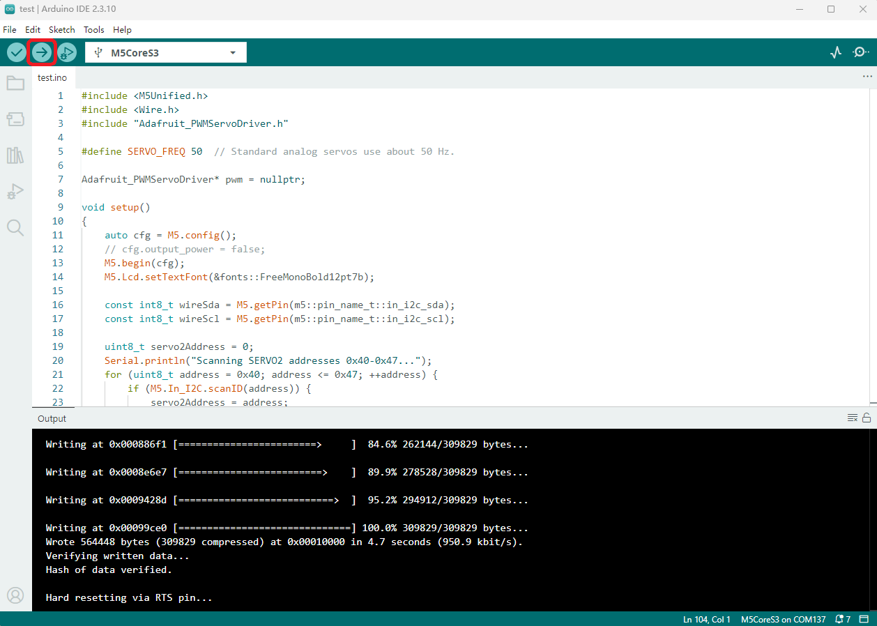
- 2. 选中设备端口,点击 Arduino IDE 左上角编译上传按钮,等待程序完成编译并上传至设备。
5. 舵机驱动
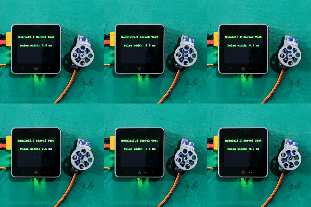
- 上电后,会自动初始化 Module13.2 Servo2 模块,然后循环设置 0.5ms / 2.5ms 脉宽的脉冲驱动舵机。
说明
例程代码实际驱动 16 个通道,下方图片中仅一个通道连接舵机进行演示。
Page Tools